![]()
![]()
Sample Water Flow Control Module
with FS-100 Ultrasonic Flow Meter + Regulating Valve
Pyxis Lab® Inc.
1729 Majestic Dr. (Suite 5)
Lafayette, CO 80026
www.pyxis-lab.com
START-UP GUIDE
![]()
![]()
INSTRUCTION GUIDE
1. Product Description
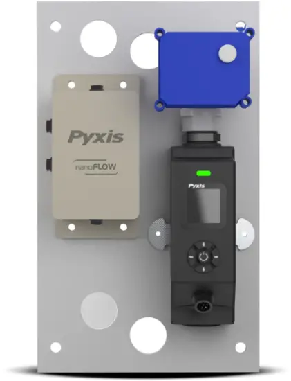
The Pyxis Nano-Flow Control Module is a stand-alone water flow measurement and control solution designed for use in critical cooling and process-water sample flow applications. This unique platform provides precise flow measurement and regulation and may be installed upstream of inline sensors in water systems that are subject to pressure and flow variation challenges. The NanoFlow module is offered in a convenient and easy to integrate micropanel mounted format for rapid installation, setup and maintenance. The micro-panel design is equipped with the Pyxis FS-100 ultrasonic flowmeter with display, which directly controls a pre-mounted regulating valve through a simple to program user interface.
The new Pyxis FS-100 is a state-of-the-art ultrasonic flowmeter that operates on the principle of transit time difference with a measurement range of 0 – 3,000 mL/min and resolution of 1mL. The sensors advanced PCB design offers built-in temperature compensation to eliminate the effect of temperature with instantaneous, accumulated, and controlled water flow based on user setpoint within the sensor itself.
The flow control module also incorporates an electric box for panel power supply, internal regulating valve control and FS-100 output flow signal wiring with both 4-20mA and RS-485 Modbus for connection to any OEM controller, PLC or DCS.
Nano-Flow Control Module (P/N 21329)
1.1 Features
- Panel Mounted for Simple Installation and Startup
- Ultrasonic Flow Meter with Local Display capable of 0 – 3,000 mL/minute measurement
- Pre-wired regulating valve controlled via user programmed ultrasonic flow meter setpoint
- Dual Flow Meter Signal Outputs: isolated 4–20 mA and RS-485 Modbus
- Real – time flow rate trend chart
- Built-in temperature sensor automatically compensates the effect of temperature on flow-rate
- Monitor and display instantaneous flow rate and accumulated volume
- Large color LED indicator for operational state indication
2. Specifications
|
Item |
Nano-Flow Control Module |
| P/N |
21329 |
|
Supported Fluid |
Liquids (water) |
| Supported Fluid Temperature |
4°C ~ 49°C (40°F ~120°F) |
|
Wet End Material of Construction |
Regulating Valve: CPVC + PTEE + Fluorine rubber FS-100: UPVC + PPS Plastic + GF Polymer + Epoxy+ Fluorine rubber |
| Sample Inlet Pressure |
7.25 – 100 psi (0.01 – 0.690 MPa) |
|
Sample Inlet /Outlet |
1/2 – inch NPT |
| Flow Path Inner Diameter |
5mm |
|
FS-100 Rated Flow Range |
0 – 3,000 mL/min |
| FS-100 Resolution |
1mL/min |
|
FS-100 Maximum Error |
±1% of the value |
| FS-100 Display |
1.44” Color 128 x128 Resolution |
|
FS-100 Analog Output(1) |
1# 4-20mA for flow rate 2# 4-20mA for regulating valve (internally connected) |
| FS-100 Digital Output |
RS-485 |
|
Regulating Valve Control Methodology |
4-20mA from FS-100 |
| Panel Power Supply |
24V DC, 6W |
|
Panel Operation Temperature |
32 – 122 °F (-0 – 50 °C) |
| Panel Storage Temperature |
-4 – 158 °F (-20 – 70 °C) |
|
Panel Dimension (H x W x D) |
300mm H x 180 mm W x 108mm D |
| Panel Approximate Weight |
~ 1.8 kg |
|
Humidity |
5 – 95% No Condensation |
| Protection |
IP-65 Panel-Display / IP-67 Regulating valve |
|
Regulation |
CE / RoHS |
*NOTE* (1) The flow control module supports only one 4-20mA (flow rate) output for connection to another device. A second 4-20mA output is internally connected and used to control the regulating valve. (2) Specifications are subject to change without notice. Contact service@pyxis-lab.com for any questions.
3. Unpackaging The Nano-Flow
The Nano-Flow Control Module package includes the following items:
- Nano-Flow Control Module (P/N: 21329)
- Includes one pre-mounted/prewired regulating valve
- Includes electric Box
- Includes one FS-100 ultrasonic flowmeter (P/N: 54200)
- Includes one CE-FE-4.9 Flying Lead Cable with Female 7-Pin Adapter – 1.5m/4.9 feet (P/N: 50762)
- Includes one MA-AC-7US 110VAC-24VDC Cable w/Plug & Female 7-Pin Adapter – 1.5m/4.9 feet (P/N: 26398)
4. Replacement / Optional Accessories
The following optional and replacement accessories are also available from Pyxis Lab.
|
Item Name/Description |
P/N |
| FS-100 ultrasonic flowmeter Replacement |
54200 |
|
Nano-Flow Motorized Valve Replacement |
21972 |
| Nano-Flow Electric Control Box Replacement |
22123 |
|
CE-FE-4.9 Explosion Proof Flying Lead Cable with Female 7-Pin Adapter 1.5m (4.9ft) |
50762 |
| MA-AC-7US Power outlet adapter cable with USA/Type A plug 110VAC-24VDC |
26398 |
|
MA-AC-7EU Power outlet adapter cable with EU/DIN plug 230VAC-24VDC |
28787 |
5. Dimensions
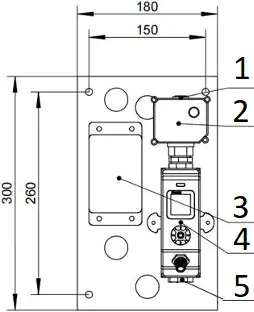
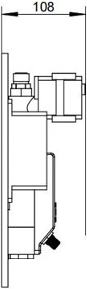
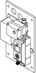
Figure 1 – Panel Dimensions(mm)
- Water Outlet
1/2″ NPT - Regulating Valve
- Electric box
- FS-100
- Water Inlet
1/2″ NPT
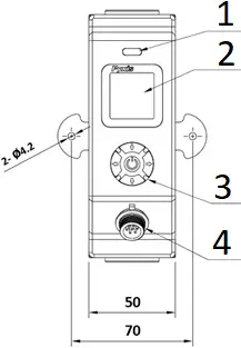
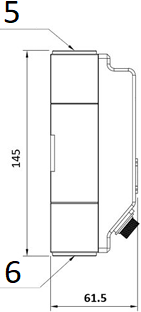
Figure 2 – FS-100 Dimensions(mm)
- Indicator Light
- Display
- Keys(5)
- 7 Pin Adapter
- Water Outlet
1/2″ NPT - Water Inlet
1/2″ NPT
6. Electrical Connection
The flow control module contains an electrical box for panel power supply (top left adapter), internal regulating valve control (top center adapter) and FS-100 output flow signal wiring (bottom left adapter). The electrical box provides 1x 4-20mA output signal and 1x RS-485 signal of the FS-100 flowmeter to be PASSED-THROUGH to another receiving device. Users should connect with the 7-Pin Explosion-proof Female Adapter / Flying Lead Cable (1) that is provided with each Nano-Flow Control Module and refer to the wiring table below for proper wiring of flow signal and 24VDC power (if desired) to receiving device. *NOTE* Each NanoFlow comes with one MA-AC-7US (110VAC to 24VDC) power supply cable with USA-Plug Type A for direct power from outlet, eliminating the need to power via 24VDC flying lead wires in bottom adapter. For EU power supply cable Pyxis offers MA-AC-7EU (220VAC to 24VDC) power supply cable with EU-DIN plug as an optional accessory. Please refer to Section 4.0 for order details.

- To Regulating Valve
- To FS-100 Flowmeter
- Signal Output
- Power Supply
Power Supply from An Outlet (TOP LEFT 7-PIN ADAPTER)
| Power Cable Provided | Description |
| MA-AC-7US (P/N 26398) | 110VAC-24VDC Type A Plug / 7Pin Female |
*NOTE* Only use MA-AC-7US if you are not powering via 24VDC flying lead wires from bottom adapter.
Signal Output and Power Supply via 24VDC Flying Lead (BOTTOM LEFT 7-PIN ADAPTER)
| Wire Color | Designation |
| Red | 24VDC+ (6 watts) |
| Black | 24VDC- & 4-20mA – (Common Ground) |
| White | 4-20 mA+ for Flow |
| Green | Not Used |
| Blue | RS-485 A |
| Yellow | RS-485 B |
| Silver | Earth Ground |
*NOTE* the CC-FE-4.9 Flying Lead Wire Offers 24VDC Power if user doesn’t desire to use MA-AC-7US outlet power cable.
|
Default 4-20mA Signal Pass-Through From FS-100 Flowmeter |
||
| Unit of Measure | 4mA Value |
20mA Value |
|
Flow Rate (mL/min) |
0 mL/min |
3000 mL/min |
7. FS-100 Operation
7.1 Key Function
![]() Enter Key
Enter Key
– Main screen → Setting Menu.
– Confirms and saves the input values.
![]()
![]() Left / Right Key
Left / Right Key
– Main screen → Trend Chart.
– Move the cursor to the left or right.
– Turn pages on the screen.
![]()
![]() Up / Down Key
Up / Down Key
– To increase or decrease a displayed number value.
– Jump up and down in the operating menu.
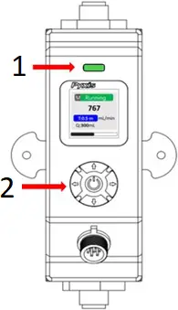
- Indicator Light
- Keys(5)
LED Status Indicator
The status LED is used for a quick visualization of the flowmeter status.
| LED Behavior | Status |
| Green | Normal Running |
| Red | Alarm Information |
7.2 Main Screen
Main Screen Description
| NO. | Description |
| 1 | Flow Detection Mode (1) |
| 2 | Working Status (same color as LED status indicator) |
| 3 | Flow Rate Value |
| 4 | Timer (2) (unit: auto range) |
| 5 | Unit of measured flow value |
| 6 | Accumulated Flow Value (unit: auto range) |
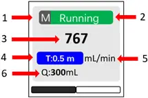
(1) R = Average Flow Rate Mode / M = Instantaneous Flow Rate Mode / C = Flow Rate Control Mode
*NOTE* For C-Mode please refer to Section 7.5 for programming details.
(2) The Timer feature is enabled when the FS-100 is powered on. It can be set by pressing the ![]() key.
key.
– Pause or Restart the Timer: Press ![]() key momentarily and release.
key momentarily and release.
– Reset the Timer: Press and hold ![]() key for about two seconds.
key for about two seconds.
(3) Calculation of the accumulated flow and Timer work synchronously, i.e., when the Timer is pause, pause display value; when the timer is resume, normally display the value; when the Timer is reset, clear the value.
7.3 Trend Chart
From the main screen, Press ![]() or
or ![]() to the trend chart display. Flow values will be displayed as a line graph to show the real-time trend. Press
to the trend chart display. Flow values will be displayed as a line graph to show the real-time trend. Press ![]() or
or ![]() to return to the main screen.
to return to the main screen.
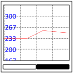
Figure 3
7.4 Alarm Settings
Press ![]() or
or ![]() in the setting menu and select [Alarm]. From Alarm settings screen, press
in the setting menu and select [Alarm]. From Alarm settings screen, press ![]() or
or ![]() to adjust the displayed number, then press
to adjust the displayed number, then press ![]() to move the cursor to “Yes”. *NOTE* To enable the alarm function, the Detection Time(s) must ≥1 second.
to move the cursor to “Yes”. *NOTE* To enable the alarm function, the Detection Time(s) must ≥1 second.
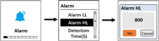
Figure 4
The Upper Alarm (Alarm HL) and Lower Alarm (Alarm LL) limit are constantly compared with flow rate value. Once the flow rate value exceeds the alarm upper limit or falls below the lower alarm limit, and the duration time is longer than the detection time, the main screen and LED indicator will display a ![]() alarm status as shown in Figure 5.
alarm status as shown in Figure 5.
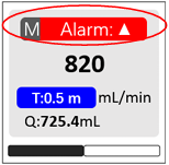
Figure 5
7.5 Set the Operating Mode for the FS-100
Press ![]() or
or ![]() in the setting menu and select [Pattern]. The following operating modes are available:
in the setting menu and select [Pattern]. The following operating modes are available:
- Flow Rate = Display the average flow rate
- Flow Meter = Display the instantaneous flow rate
- Flow Control = Set a desired constant flow rate
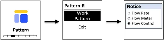
Figure 6
If the user selects Flow Control mode, a preset flow rate must be entered (Figure 7). The FS-100 will control the regulating valve according to the preset flow rate.
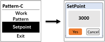
Figure 7
*NOTE* If the actual flow rate does not reach the preset flow rate, and duration time is longer than two minutes, the main screen and LED indicator will display red alarm status ![]() .
.
7.6 Communication Settings
Press ![]() or
or ![]() in the setting menu and select [Com] to modify communication parameters (Figure 8).
in the setting menu and select [Com] to modify communication parameters (Figure 8).
The following communication settings are available:
- Modbus Address (Range: 1~247)
- Baud Rate (Options: 9600 / 38400 / 57600 / 115200)
- Parity (Options: None / Odd / Even)
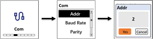
Figure 8
7.7 Calibration
During flow meter ZERO & SLOPE calibration, the FS-100 must be set to instantaneous flow mode. *NOTE* Please refer to Section 7.5 to set the operating mode for FS-100).
7.7.1 Two-Point Calibration
Zero Calibration: This function is used to correct the instantaneous flow rate to “ZERO”. *NOTE* To perform zero calibration the pipe must be filled with fluid and the fluid should not be moving.

Figure 9.
Slope Calibration: This function is used to calibrate the accumulated flow value. Determine the accumulated flow value of the sample water over a period of time by using the electronic balance. The user can customize the sampling time to their preference.
1. Turn off the water valve and place the water outlet line in a beaker.
2. From the main screen, reset the Accumulated Flow Value (Q) to 0.00mL by pressing and holding the ![]() key for about two seconds.
key for about two seconds.
3. Quick Press the ![]() key to restart the calculation of the accumulated flow value. Turn on the water valve and fill the beaker with water.
key to restart the calculation of the accumulated flow value. Turn on the water valve and fill the beaker with water.
4. Navigate to Slope Calibration screen and enter the measured value of the shot amount as noted by the electronic balance (as grams). *NOTE* 1-mL of water weighs 1-gram.

Figure 10.
- Live accumulated flow value
5. If the calibration was successful, the interface will return a message “calibration succeed”.
7.8 Regulating Valve Output – 4-20mA Span
The FS-100 series flow meter controls the valve position of the regulating ball valve by outputting the 4-20 mA signal. After the user assigns a desired flow set point in Flow Control (C) mode, the FS-100 series will automatically calculate the error between the actual flow rate and the setpoint flow rate and adjust the appropriate 4-20mA output value through the preprogrammed PID algorithm to regulate the valve. This advanced capability and feature provides turn-key and real-time application use resulting in the sample flow rate infinitely close to the user programmed setpoint value. See process diagram below.

Figure 11
7.9 Flow Measurement Output – 4-20mA Span
Press ![]() or
or ![]() in the setting menu and select [4-20mA Out] to change the 4-20mA output corresponding to the flow rate. See Figure 12 for details. *NOTE* The default 420mA output of the FS-100 flowmeter is scaled as: 4mA = 0 mL/min, 20 mA = 3000 mL/min.
in the setting menu and select [4-20mA Out] to change the 4-20mA output corresponding to the flow rate. See Figure 12 for details. *NOTE* The default 420mA output of the FS-100 flowmeter is scaled as: 4mA = 0 mL/min, 20 mA = 3000 mL/min.
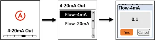
Figure 12
7.10 Display Screen Orientation Settings
Press ![]() or
or ![]() in the setting menu and select [Screen] to select the display orientation of the screen.
in the setting menu and select [Screen] to select the display orientation of the screen.
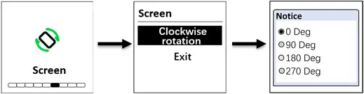
Figure 13
7.10 Device Information
Press ![]() or
or ![]() in the setting menu and select [Info]. This screen contains the device name, serial number, software version, and hardware version (Figure 14)
in the setting menu and select [Info]. This screen contains the device name, serial number, software version, and hardware version (Figure 14)
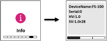
Figure 14 Device Information
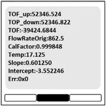
Figure 15 Diagnosis
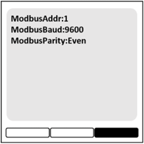
Figure 16
Press ![]() or
or ![]() to turn the page. This screen information has no use for normal operation, but instead is used for device troubleshooting. Provide an image of both the DEVICE INFORMATION screen and the DIAGNOSIS screen when you contact Pyxis (service@pyxis-lab.com) for troubleshooting your device or call +1 866-203-8397 ext 2.
to turn the page. This screen information has no use for normal operation, but instead is used for device troubleshooting. Provide an image of both the DEVICE INFORMATION screen and the DIAGNOSIS screen when you contact Pyxis (service@pyxis-lab.com) for troubleshooting your device or call +1 866-203-8397 ext 2.
8. Communication using Modbus RTU
The FS-100 ultrasonic flowmeter is configured as a Modbus slave device. In addition to flow rate mL/min, many operational parameters, including warning and error messages, are available via Modbus RTU connection. Contact Pyxis Lab Customer Service (service@pyxis-lab.com) for more information.
General Communication Settings
| Baud Rate | 9600 bps |
| Data Bit | 8-bit |
| Stop Bit | 1-bit |
| Parity Check | Even |
| Bus Type | RS-485 |
Register Address of Communication Parameters (read-only)
| Register Address | Type | Byte Order | Register Definition |
| 46002 | Float | CDAB | Flow Rate |
| 46004 | Float | CDAB | Temperature Value |
| 46022 | Float | CDAB | 4-20mA for Flow |
| 46018 | Unsigned int 16 | AB | Error Code |
9. Order Details
| Order Information |
P/N |
| Nano-Flow Control Module (Ultrasonic Flow Regulating Module Panel) |
21329 |
| Optional / Replacement Accessories Information |
P/N |
| FS-100 (Ultrasonic Flow Meter with Display 0-3,000mL/Minute) |
54200 |
| Nano-Flow Motorized Valve (Replacement) |
21972 |
| Nano-Flow Electric Control Box (Replacement) |
22123 |
| CE-FE-4.9 (Flying Lead Cable with Female 7-Pin Adapter 1.5m-4.9ft) |
50762 |
| MA-AC-7US (Power outlet adapter cable with USA/Type B plug 110VAC-24VDC) |
26398 |
| MA-AC-7EU (Power outlet adapter cable with EU/DIN plug 230VAC-24VDC) |
28787 |
Nano-Flow Control Module service@pyxis-lab.com | +1 866-203-8397
Documents / Resources
 |
Pyxis Untitled Nano Flow Control Module [pdf] User Guide Untitled Nano Flow Control Module, Untitled, Nano Flow Control Module, Flow Control Module, Control Module, Module |


