![]()
Multifunctional Controller
Instruction Manual

Controller Front Layout

| NO | DESCRIPTION |
| 1 | MAIN ISOLATOR |
| 2 | FRONT PANEL LOCKING TAB x2 |
| 3 | SUNLIGHT SHIELD |
| 4 | HMI SCREEN |
| 5 | LIGHT BEACON |
| 6 | SIREN |
| 7 | ALARM RESET BUTTON |
| 8 | THREE PHASE POWER ON/OFF SWITCH |
| 9 | THREE PHASE POWER OUTLET |
| 10 | EMERGENCY STOP SWITCH |
| 11 | SINGLE PHASE POWER ON/OFF SWITCH |
| 12 | SINGLE PHASE POWER OUTLET |
Controller Internal Layout

| NO | DESCRIPTION |
| 1 | MAIN ISOLATOR |
| 2 | CIRCUIT BREAKER – 3-PHASE |
| 3 | CIRCUIT BREAKER – 1-PHASE |
| 4 | CIRCUIT BREAKER – POWER SUPPLY |
| 5 | 20A CONTACTOR |
| 6 | 16A CONTACTOR |
| 7 | CIRCUIT BREAKER – PLC & HMI |
| 8 | PLC |
| 9 | PLC EXPANSION |
| 10 | OUTPUT TESTER BUTTON |
| 11 | EARTH TERMINALS |
| 12 | NEUTRAL TERMINALS |
| 13 | INPUT & OUTPUT NUMBERING LABEL |
| 14 | 24V TERMINALS |
| 15 | 0V TERMINALS |
| 16 | INPUT / OUTPUT TERMINALS |
| 17 | 24V 5A POWER SUPPLY |
NOTE:
Polymaster removes the 240V plug that is wired into the box before shipping. It is only to be used for test purposes at Polymaster.
Input / Output Wiring

| TERMINAL LABEL | DESCRIPTION | I /O Type | Contact Type |
| 1 | BUND LEVEL SWITCH | INPUT | NC |
| 2 | LOW LOW LEVEL SWITCH | INPUT | NC |
| 3 | HIGH HIGH LEVEL SWITCH | INPUT | NC |
| 4 | INPUT EXTERNAL STOP | INPUT | NC |
| 5 | RUN DRY SENSOR | INPUT | NC |
| 6 | EXTERNAL STOP CUSTOMER CONTACT | OUTPUT | NO |
| 7 | RUN DRY CUSTOMER CONTACT | OUTPUT | NO |
| 8 | EMERGENCY STOP PRESSED CUSTOMER CONTACT | OUTPUT | NO |
| 9 | GPO POWER ENABLED CUSTOMER CONTACT | OUTPUT | NO |
| 10 | BUND ALARM CUSTOMERS CONTACT | OUTPUT | NO |
| 11 | LOW LEVEL ALARM CUSTOMERS CONTACT | OUTPUT | NO |
| 12 | HIGH LEVEL ALARM CUSTOMERS CONTACT | OUTPUT | NO |
| 13 | HIGH HIGH LEVEL ALARM CUSTOMER CONTACT | OUTPUT | NO |
| 14 | 4-20mA INPUT LEVEL SENSOR | INPUT | ANALOGUE |
| 15 | SPARE | ||
| 16 | 4-20mA LEVEL OUT CUSTOMER CONTACT | OUTPUT | ANALOGUE |
| 17 | EARTH SHIELDING |
Radar Connection
This connection is located at the bottom right of the controller.
It is located in the “INPUT/OUTPUT
TERMINALS” and is Terminal:14
Connect the wires of the Radar Sensor into the terminals shown below:

| Sensor Brand / Model | ||
| Terminal | Siemens LR100 | Vega C11 |
| + | Black | Brown |
| – | White | Blue |
| 17 | Earth Shield | |
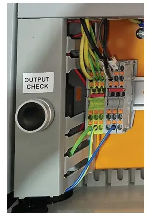
Inside the controller you can use the OUPUT CHECK button to turn on all outputs. This can be useful to test the customer contacts to ensure they give the results expected at the customers end.
Display Screens

SETUP SCREEN
To get to the setup screen press SETUP from either of the home screens.

The SETUP screen is password protected so only authorised users can edit the controller’s functionality. See the password section in Appendix 2 for these details.
Click in the white box to enter the password.

Type in the password using the keypad andthen press ENTER.

From the SETUP screen you are able to:
- Set the TANK WORKING CAPACITY.
- Select between TRUCK FILL MODE and TRANSFER STATION MODE.
- Set the REFILL LEVEL PERCENTAGE (for

Transfer Station mode)
To change between TRUCK FILL MODE & TRANSFER STATION MODE select the check box.
ENTER TANK WORKING CAPACITY
To enter the TANK WORKING CAPACITY, click the box that the value is displayed on, and the following keypad will appear. Type in the value and press ENTER to go back to the SETUP screen.
It is important to enter the correct value. See Appendix 1 for working capacity calculation.

SET REFILL LEVEL
In TRANSFER STATION MODE there is a REFILL LEVEL which is set. Once the tank is filled the power to the GPOs is disabled and will not be enabled until the level has dropped below the REFILL LEVEL. This feature stops the pump from short cycling.
To change the TRANSFER STATION MODE REFILL LEVEL PERCENTAGE click the box that the default value of 40% is displayed in. The following keypad will appear. Enter a value between 20% – 70% and then press ENTER to go back to the SETUP screen.
To go back to the HOME SCREEN press OK.

Alarm Screens
TANK LOW SCREEN
If the liquid level goes below 20% full on the Radar Sensor or the Tank Low Level Sensor goes low then the TANK LOW warning will be displayed.
Low Level Alarm Customer Contact will also be turned on.

TANK FULL SCREEN
If the liquid level goes between 85% -95% full on the Radar Sensor then the TANK FULL warning will be displayed. High Level Alarm Customer Contact will also be turned on.
Power to the GPOs will be disabled.
An audible buzzer will sound. Press Alarm Reset to silence the alarm.
Press and hold the Alarm Reset Button for 5 seconds to reenable power to the GPOs.

TANK OVER FULL SCREEN
If the liquid level goes above 95% full on the Radar Sensor or the Tank High High Sensor goes Low then the TANK OVER FULL warning will be displayed. High High Level
Alarm Customer Contact will also be turned on.
Power to the GPOs will be disabled.
An audible buzzer will sound. Press Alarm Reset to silence the alarm.

BUND ALARM SCREEN
If the Bund Sensor goes Low then the BUND SENSOR warning will be displayed.
Bund Alarm Customer Contact will also be turned on.
Power to the GPOs will be disabled.
An audible buzzer will sound. Press Alarm Reset to silence the alarm.

BUND & TANK OVER FULL ALARM SCREEN
If the Bund Sensor goes Low and the RADAR is measuring above 95% then the BUND SENSOR & TANK OVER FULL warning will be displayed. Bund Alarm & High High Level Alarm Customer Contacts will also be turned on.
Power to the GPOs will be disabled.
An audible buzzer will sound. Press Alarm Reset to silence the alarm.

EXTERNAL STOP ALARM SCREEN
If External Stop input goes low show the EXTERNAL STOP ALARM warning. External Stop Customer Contacts will be turned on.
Power to the GPOs will be disabled.
An audible buzzer will sound. Press Alarm Reset to silence the alarm.

RUN DRY SENSOR ALARM SCREEN
If Run Dry Sensor input goes low and the controller is in TRANFER STATION MODE show the RUN DRY SENSOR warning.
Input Run Dry Customer Contact will also be turned on.
Power to the GPOs will be disabled.
An audible buzzer will sound. Press Alarm Reset to silence the alarm.
Press and hold Alarm Reset for 5 seconds to run the pump. (Note you must keep holding the Alarm Reset Button to run the pump)
If TRANSFER STATION MODE is not selected, then none of the above happens in TRUCK FILL MODE.

EMERGENCY STOP SCREEN
If Emergency Stop is pressed the EMERGENCY STOP SCREEN will be shown.
Emergency Stop Pressed Customer Contact will also be turned on.
Power to the GPOs will be disabled.

ALARM SCREENS ORDER OF PRIORITY
If multiple alarms are active at once the most important alarm will take priority and be displayed.
| Priority | Alarm Screen |
| 1 | Emergency Stop |
| 2 | Bund Sensor & Tank Over Full |
| 3 | Bund Sensor |
| 4 | Tank Over Full |
| 5 | External Stop |
| 6 | Pump Run Dry |
| 7 | Tank Fu l l |
| 8 | Tank Low |
Appendix 1
TANK WORKING CAPACITY
A 10,000 Litre tank can not hold a working capacity of 10,000 Litres due to the overflowpoint. Therefore, the value entered into the SETUP SCREEN is important to be correct and needs to be calculated for each individual tank.
The following section shows how to calculate the Tank Working Capacity and gives examples of values for our standard tanks.
However, each tank should be checked as manufacturing tolerances may affect this.
WORKING AREA
The working area is the area inside the internal wall diameter. Examples of our tank range sizes are shown to the right.
| Tank Capacity (Litres) | Internal Diameter of Tank (m) | Working Area of Tank (m2) | Working Area of Tank *1000 |
| 1500 | 0.986 | 076 | 760 |
| 2300 | 1.280 | 1.29 | 1290 |
| 3300 | 1.508 | 179 | 1790 |
| 5000 | 1.932 | 2.93 | 2930 |
| 7000 | 2.190 | 3.77 | 3770 |
| 10000 | 2.380 | 4.45 | 4450 |
| 13000 | 2.802 | 6.17 | 6170 |
| 21000 | 3.044 | 7.28 | 7280 |
| 30000 | 3.550 | 9.9 | 9900 |
WORKING HEIGHT
Working Height of Tank = Height from ground to bottom of overflow pipe – Tank Base Thickness.
= (Measured Value) – 0.01m
= m
To be exact you need to measure the realworld value. However, for our standard tanks that have not been customised the following table shows the working heights: (Note: This is for a Standard 90 PE fitting position)
| Tank Capacity (Litres) | Height to bottom of Overflow (m) | Tank Base Thickness (m) | Tank Working Height (m) |
| 1500 | 1.826 | 0.01 | 1.825 |
| 2300 | 1.660 | 0.01 | 1.650 |
| 3300 | 1.715 | 0.01 | 1.705 |
| 5000 | 1.635 | 0.01 | 1.625 |
| 7000 | 1.722 | 0.01 | 1712 |
| 10000 | 2.080 | 0.01 | 2.070 |
| 13000 | 2.060 | 0.01 | 2.050 |
| 21000 | 2.822 | 0.01 | 2.812 |
| 30000 | 2.926 | 0.01 | 2.916 |
TANK WORKING CAPACITY
Tank Working Capacity = Working Area (m2 *1000) x Working Height (m)
=
Use the following table and multiply by working height to find the Tank WorkingCapacity.
| Tank Capacity (Litres) | Working Area (m2 *1000) |
| 1500 | 760 |
| 2300 | 1290 |
| 3300 | 1790 |
| 5000 | 2930 |
| 7000 | 3770 |
| 10000 | 4450 |
| 13000 | 6170 |
| 21000 | 7280 |
| 30000 | 9900 |
Standard Tanks with 90 PE Overflow
For our standard tanks with 90 PE Overflow in the standard fitting position the following table applies.
| Tank Capacity (Litres) | Working Area(m2*1000) | Working Height (m) | Working Capacity (Litres) |
| 1500 | 760 | 1.825 | 1393 |
| 2300 | 1290 | 1.650 | 2123 |
| 3300 | 1790 | 1.705 | 3045 |
| 5000 | 2930 | 1.625 | 4764 |
| 7000 | 3770 | 1.712 | 6449 |
| 10000 | 4450 | 2.070 | 9209 |
| 13000 | 6170 | 2.050 | 12641 |
| 21000 | 7280 | 2.812 | 20464 |
| 30000 | 9900 | 2.916 | 28863 |
Appendix 2
PASSWORD
The password is a conversion of the last 4 digits of the MAC address of the HMI screen from hexadecimal to decimal.
For example the HMI MAC ADDRESS can be found here:

The last 4 digits are E9F1
Use the following link to use a Hexidecimal to Decimal converter: https://www.rapidtables.com/convert/number/hex-to-decimal.html
The password is therefore: 59889
![]()
1800 062 064
polymaster.com.au
Follow us: Polymaster Group
![]()
PUB-2024-10
Documents / Resources
 |
Polymaster Vega C11 Multifunctional Controller [pdf] Instruction Manual LR100, C11, Vega C11 Multifunctional Controller, Vega C11, Multifunctional Controller, Controller |