![]() ESR Series
ESR Series
User Guide
ESR106 ESR2600D

The Future of Sound. Made Perfectly Clear.
At KV2 Audio our vision is to constantly develop technologies that eliminate distortion and loss of information providing a true dynamic representation of the source.
Our aim is to create audio products that absorb you, place you within the performance and deliver a listening experience beyond expectations.
ESR Series· Important Safety Instructions
Important Safety Instructions
Before using your ESR Series, be sure to carefully read the applicable items of these operating instructions and the safety suggestions.
- Read all product instructions.
- Keep printed instructions, do not throw away.
- Respect and rewiew all warnings.
- Follow all instructions.
- Do not use this unit near water, in unprotected out door areas or in rain or wet conditions.
- Clean only with dry cloth.
- Do not block any ventilation openings.
- Install in accordance with KV2 Audio’s recommended installation instructions.
- Do not install near any heat sources such as heat radiators, heat registers, stoves or other apparatus that produce heat.
- Do not defeat the safety purpose of the grounding type plug. A grounding type plug has two blades and a third grounding connector. The third connector is provided for your safety. If the provided plug does not fit into your outlet, consult an electrician for replacement of the obsolete outlet.
- Protect the power cord from being walked on or pinched, particularly at plugs, convenience receptacles. The AC mains plug or appliance coupler shall remain readily accessible for operation.
- Only use accessories specified by KV2 Audio.
- Install the product only with rigging specified by KV2 Audio, or sold with the loudspeaker.
- Unplug this loudspeaker during lightning storms or when unused for long periods of time.
- Refer all servicing to qualified service personnel. Servicing is required when the loudspeaker has been damaged in any way, such as when the power-supply cord or plug has been damaged; liquid has been spilled or objects have fallen into the loudspeaker; rain or moisture has entered the loudspeaker; the loudspeaker has been dropped; or when for undetermined reasons the loudspeaker does not operate normally.
- Do not remove front or back panels. Removal of the panel will expose hazardous voltages. There are no user serviceable parts inside and removable may void the warranty.
- An experienced user shall always supervise this professional audio equipment.
CAUTION: TO REDUCE THE RISK OF ELECTRIC SHOCK, DO NOT REMOVE THE PANELS.
NO USER-SERVICEABLE PARTS INSIDE. REFER SERVICING TO QUALIFIED PERSONNEL.
WARNING: To prevent fire or electric shock, do not expose this equipment to rain or moisture.
SAFETY SUMMARY
To reduce the risk of electric shock, disconnect the loudspeaker from the AC mains before installing audio cable.
Reconnect the power cord only after making all signal connections. Connect the loudspeaker to a twopole, three- wire grounding mains receptacle. The receptacle must be connected to a fuse or circuit breaker. Connection to any other type of receptacle poses a shock hazard and may violate local electrical codes. Do not allow water or any foreign object to get inside the loudspeaker. Do not put objects containing liquid on or near the unit. To reduce the risk of overheating the loudspeaker, avoid exposing it to direct sunlight. Do not install the unit near heat-emitting appliances, such as a room heater or stove. This loudspeaker contains potentially hazardous voltages. Do not attempt to disassemble the unit. The unit contains no user serviceable parts, repairs should be performed only by factory trained service personnel.
ESR Brackets and Flybars· Introduction· Warning
Introduction
This manual is presented by KV2 Audio, to enable the clear and precise instructions for the safe practice and execution of overhead suspension, or flying of the KV2 Audio ESR Full range Loudspeaker products, using the ESR BRACKETS and FLYBARS.
It is vitally important that operators and users familiarize themselves with all of the components, parts, products and safety instructions, as described and indicated within this document, before attempting any overhead suspension of the ESR Brackets and Flybar systems.
The ESR Loudspeaker enclosures are designed with integral suspension points to facilitate secure vertical and Horizontal suspension and rigging, providing that no modifications or external parts are substituted, and that all instructions are adhered to at all times.
KV2 Audio operates a continuing process policy of attaining and improving standards.
This means that instructions and methods may be subject to change without notification, and it is the sole responsibility of the operator/user to check for any updated information regarding safe stacking and flying procedures whether locally or Internationally.
Warning – Safety Rigging
There are accepted ‘General Rigging Practices’ appropriate to the entertainment industry and this Document aims to encapsulate them specifically to the safe vertical and horizontal suspension of the KV2 ESR Loudspeaker systems described here.
It is extremely vital and important that only personnel whom have the qualifications and certificates, Prior knowledge and experience of rigging techniques, attempt the execution of any suspension configuration utilizing the ESR Brackets and Flybars for the KV2 ESR products.
All advice and instructions expressed and stated within this document, are based upon the highest engineering data available at the time of publication, from within the Country of manufacture, with regards to materials and general practice techniques.
Specifications are subject to change, due to constant testing, product updates and refinements and R&D.
‘General Rigging Practices’ means that Regulations and requirements are possibly subject to alterations in different countries and may be superseded locally.
KV2 Audio, as such is not responsible for the safety of any suspension, flying overhead of all specific KV2 Audio Loudspeaker products, or Rigging configurations as executed in practice by users.
It is expressly the sole responsibility of the user to ensure that at all times any KV2 Audio product, or system is Ground stacked, suspended and rigged in accordance with current International and local regulations.
All non KV2 Audio products such as hoists, clamps, wires, truss, supports used, or required to assure stability, or suspend KV2 Audio Loudspeaker product are the sole responsibility of the user.
Warranty
Your ESR Brackets and Flybars are covered against defects in material and workmanship.
Refer to your supplier for more details.
Service
In the unlikely event that your ESR Brackets and Flybars develop a problem, it must be returned to an authorized distributor, service center or shipped directly to our factory. Because of the complexity of the design, only qualified technical personnel must attempt all repairs.
If the unit needs to be shipped back to the factory, it must be sent in its original carton, or suitable alternatives. If improperly packed, the unit maybe damaged in transit.
To obtain service, contact your nearest KV2 Audio Service Centre, Distributor or Dealer.
ESR106· Introduction

Application
- Fixed Installations
- Theatres & Auditoriums
- Concert Halls
- Houses of Worship
- ALWAYS used in a vertical orientation
Introduction
The ESR106 is an active driven 3 way system employing a unique column array of multiple 6“ woofers for unparalleled high quality vocal and music reproduction in challenging acoustical spaces and ambient environments.
Utilising 8 x 6“ woofers, 2 x 6“ mid bass woofers and a single 1“ high frequency driver mounted on a wide dispersion horn, the ESR106 is constructed to represent one large point source, with each part of the system positioned so that it is proportional in size to the wavelength it produces, thus the radiated power of each band remains consistent
and balanced throughout the system’s overall frequency range. The ESR106 has a controlled coverage at low and mid frequencies to reduce indoor reflections.
The ESR106 has a controlled coverage at low and mid frequencies to reduce indoor reflections.
The ESR106 is controlled and driven by a dedicated ESR2600D amplifier, using KV2 Audio proprietary SLA technology.
Features
- Full range 3 way system incorporating state of the art multiple transducers.
- Multi point fixings for external brackets and flyware.
- True musical solution for speech, vocals and music playback in difficult acoustical environments.
ESR Full Range Sound System Benefits
Total flexibility
ESR Series does not require a large number of speakers. It provides a full range, very high quality sound from a single, small, discreet source. For extended bass choose from a wide range of KV2 Audio subwoofers. The subwoofers can be placed in a convenient remote location, due to the low 70Hz crossover point between an ESR106 module and the subwoofer.
Superb sound
Greater dynamic range than standard column or steerable speaker designs, featuring VHD (Very High Definition) technology with Super Analog amplifier technology.
Easy set-up
Plug-and-play connection to the ESR2600D amp/processor module. Cabinet features side handles and sixteen M10 suspension points.
ESR106· Specifications
Specifications
| System Acoustic Perfomance | |
| Max SPL Long-term | 128dB |
| Max SPL Peak | 134dB |
| -3dB Response | 60Hz to 20kHz |
| -10dB Response | 52Hz to 28kHz |
| Crossover Point | 450Hz, 2.4kHz |
| High Frequency Section | |
| Acoustic Design | Horn Loaded |
| High Horn Coverage Horizontal / Vertical | 100° x 80° |
| Power Handling | 100W from ESR2600D Amplifier |
| Rotatable Horn | NO |
| Throat Exit Diameter / Diaphragm Size | 1″ / 1.75″ |
| Diaphragm Material | Titanium |
| Magnet Type | Neodymium |
| Mid Range Section | |
| Acoustic Design | Sealed enclosure |
| Woofer Size / Voice Coil Diameter | 2x 6″ / 1,75″ |
| Power Handling | 200W from ESR2600D Amplifier |
| Diaphragm Material | Epoxy Reinforced Cellulose |
| Magnet Type | Neodymium |
| Low Frequency Section | |
| Acoustic Design | Front Loaded, Bass Reflex |
| Woofer Size / Voice Coil Diameter | 8x 6″ / 1,75″ |
| Power Handling | 1000W from ESR2600D Amplifier |
| Magnet Type | Neodymium |
| Diaphragm Material | Epoxy Reinforced Cellulose |
| Speaker Input | |
| Speaker Input | 1x AMPHENOL 6 |
| Cabinet | |
| Cabinet Material | Baltic birch |
| Handles | 4 |
| Color | Orange peeled Matt Black or any RAL |
| Physical Dimensions | |
| Height | 2048 mm (80.629″) |
| Width | 250 mm (9.842″) |
| Depth | 268 mm (10.551″) |
| Weight | 42,5 kg (93.7lbs) |
ESR106· Frequency characteristics
Frequency response

Horizontal Polar plots

Vertical Polar plots

ESR106· Drawing
Drawing

ESR106 Architects and Engineer’s Specifications
The three-way loudspeaker system shall incorporate eight 6-inch low frequency (LF) transducers, two 6-inch mid-range (MR) transducers and a 1-inch exit compression driver high frequency (HF) transducer. The LF drivers shall be mounted above and below the mid-high horn tuned for optimum mid-bass response and dispersion. The HF transducer shall be loaded on an integrated, constant directivity horn assembly.
The loudspeaker enclosure shall have a rectangular shape and shall incorporate two handles on each vertical side.
The Enclosure incorporates sixteen M10 suspension points, three M10 suspension points on each vertical side, four M10 suspension points on the top and bottom and two on the rear panel side. The speaker cabinet shall be finished with an ultra wear resistant black polymer coating and fitted with a weather resistant perforated steel grill.
The system shall receive power from a separate ESR2600D Amplifier.
The ESR2600D Stereo (two channel) Amplifier/Controller Module consists of separate power amplifiers for high, midrange and mid bass transducers as well as signal processing including electronic band pass crossover filters, phase alignment, time correction, equalization and speaker protection. The speaker system shall connect to the Amplifier/Controller Module via proprietary cables terminated in Amphenol AP-6 connectors.
The three-way loudspeaker system shall be the KV2 Audio ESR106.
ESR2600D · Introduction
ESR2600D – part number KVV 987 514 (250V)
KVV 987 513 (230V)
KVV 987 512 (115V)
Application
Specifically designed as the amplification and control unit for the ESR106 loudspeaker system in a 4RU mount module with integrated Control & Diagnostics.
- Fixed Installations
- Theatre and Music venues
- Houses of worship
- Classical and opera concerts
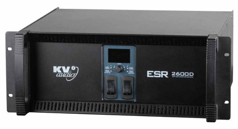
Introduction
ESR2600D Amplifier with Control & Diagnostics
The ESR2600D is a two channel (stereo) three-way, active control and amplification system specially designed for the KV2 Audio ESR106 full range loudspeaker system. It houses all signal processing and amplification, as well as providing control and crossover functions for adding external subwoofer cabinets if required, utilizing external amplifiers. The ESR26000D is now configurable via the front panel or remotely using the KV2 Control & Diagnostics Tool.
The ESR2600D incorporates six amplifiers consisting of two 100-watt, Class AB, push pull, low intermodulation amplifiers for high frequencies, two 200-watt, Class AB, push pull, low intermodulation design amplifiers for mids and two 1000-watt, high-efficiency, current-enhancing switching technology amplifiers for bass. The ESR2600D stereo configuration powers two ESR cabinets accordingly.
Features
The amplifier compliment inside the ESR2600D Amplifier is as follows:
- High Frequency – 2x 100-watt, Class AB, push pull, low intermodulation design
- Mid Frequency – 2x 200-watt, Class AB, push pull, low intermodulation design
- Low Frequency – 2x 1000-watt, high-efficiency, current-enhancing switching design Configurable via the front panel or remotely using the KV2 Control & Diagnostics Tool.
Front Panel:


ESR2600D· Getting Started
Unpacking
Unpack the ESR2600D Amplifier and check for any damage. If you find any damage, notify your supplier immediately. Only the consignee may institute a claim with the carrier for damage incurred during shipping. Be sure to save the carton and all packing materials for the carrier’s inspection. Should you ever need to ship the unit, only use the original factory packaging.
If the shipping carton is unavailable, contact your supplier to obtain a replacement.
The ESR2600D Amplifier carton should contain:
- ESR2600D Amplifier control unit
- This user guide
- Two PowerCon detachable power cables
Amplifier rack mounting
The ESR2600D Amplifier is 4 rack units in height and will mount in standard 19″ rack system. Integral rear mounting rack ears are also provided for additional support, do not rely on fixing and mounting the amplifier using just the front panel as support. Use eight screws and washers to mount the amplifier to the equipment rack rails. We recommend using a shock mounted rack for touring use to prolong the life of your amplifier.
Cooling
The ESR2600D Amplifier has a comprehensive cooling system featuring chassis sealed PCB board mounting and shock mounted, speed controlled fans. This means that the cooling system never drives air across PCB boards, connectors or components, ensuring prolonged electronic component lifespan and minimizing maintenance cycles.
Air is drawn into the front of the amplifier by the two fans on the rear panel, this passes over the cooling fins of the heat sinks and exhausts through the rear. If the heat sink gets too hot, its sensing circuit will open the output relay, disconnecting the load.
It is important to have an adequate air supply at the front of the amplifier, and enough space around the rear of the amplifier to allow the cooling air to escape. If the unit is rack mounted, do not use doors or covers on the rear of the rack, the exhaust air must flow without restriction. If you are using racks with closed backs, use fans on the rear rack panel to ensure an ample air supply.
IMPORTANT! Please note that for correct full performance of the unit AND ANY WARRANTY COVER, it is important that regular maintenance of the front vents and filters as well as the rear panel fans be inspected and cleaned by removing any dust and debris build-up. Any product failure due to lack of attention in this matter will immediately void any current warranty. (Please refer to notes re ventilation procedures).
ESR2600D · Getting Started
AC Requirements
Two PowerCon cables are provided to connect the ESR2600D Amplifier to suitable AC power supplies. Each cable powers each separate amplifier channel for sufficient current delivery.
THE ESR2600D REQUIRES A GROUND CONNECTION. ALWAYS USE A GROUNDED OUTLET AND PLUG.
The PowerCon is a connector without any circuit breaking capability, i.e. the PowerCon should not be connected or disconnected under load or while it is live. Always isolate your AC supply before disconnecting the PowerCon connector.
The ESR2600D amplifier operates in either 115V, 230V or 250V modes. Although pre-configured at the factory, the unit’s operating voltage mode can be changed in the field. The Amplifier power plug must be fully removed before any attempt is made to change the operating voltage. The power cord must always be easily accessible for a quick disconnection from the power outlet, if required.
Your amplifier will be supplied preset to the voltage used in your area. The table below provides typical current draw figures for the ESR2600D Amplifier.
The receptacle must be connected to a fuse or circuit breaker. Connection to any other type of receptacle poses a shock hazard and may violate local electrical codes.
Do not allow water or any foreign object to get inside the amplifier. Do not put objects containing liquid on or near the unit.
To reduce the risk of overheating the amplifier, avoid exposing it to direct sunlight.
Do not install the unit near heat-emitting appliances, such as a room heater or stove. This amplifier contains potentially hazardous voltages. Do not attempt to disassemble the unit. The unit contains no user serviceable parts, repairs should be performed only by factory trained service personnel.
| AC Input | Current draw with amplifier running at Average Power (Each Channel) |
Current draw with amplifier running at Peak Power (Each Channel) |
| 250V | 3.2A | 5A |
| 230V | 3.5A | 5.4A |
| 115V | 7A | 11A |
Current draw of ESR2600D Amplifier
ESR2600D· Front panel
Front Panel

- AC Mains Switch
The ESR2600D has combination AC mains switch/circuit breakers on the front panel. If either of the switches shut off during normal use, push it back to the ON position once. If it will not stay on you should take the unit to qualified service personnel to have it serviced. - Power / Thermal
These are dual colour LED’s. When green they indicate that the Power Switch is ON and that channel of the amplifier is powered up. When red they indicate that that channel has overheated and shut down. The unit will Auto Reset after it cools down to a safe operating temperature. - Signal / Speaker Protection
Indicator These are dual colour LED’s. When green they indicate that signal is present at the Input to that particular channel of the amplifier. When yellow they indicate that the audio speaker protection limiter has been activated for that particular channel of the amplifier. - Display
Shows the set parameters and allows settings of various functions in the menu. - Rotation encoder with Enter push-button
The encoder serves as the main way for increasing (clockwise), or decreasing (counter clockwise) values and menu positions. The encoder also serves as the ENTER (PUSH) button, allowing the operator to enter/leave the submenu in the main menu.
ESR2600D· Rear panel
Rear Panel ESR2600D

- Main Input / Through Out
These are the input XLR connectors for channel A & B with associated ‘Through Output’ connectors for sending signal to other devices. - Sub out Balanced XLR output connector
Sub out Balanced XLR output connector, crossed over LPF, used to connect additional subwoofers. This output is still active even when FULL RANGE mode is activated. - PowerCon Power Connector
The ESR2600D Amplifier uses one AC PowerCon connector per channel. Each connector supplies one channel. They accept standard PowerCon terminated AC Mains cables. - Fans
The cooling fans operate continuously while the ESR2600D is on. An internal temperature sensor increases the speed of the fans during high temperature conditions. Air enters through the front grille and exits through the rear. Be sure to allow adequate air flow to the front of the rack in which the ESR2600D is mounted.
 Communication
 - Reset
Serves as factory reset button for the control and diagnostics section. Resets all setup, including network settings (default
settings AutoIP/DHCP). Use a tool with maximum diameter 2mm. - Status
LEDs indicates amplifier and amplifier diagnostics status, these are:
AMP
Dual colour LED. When green, it indicates that the power amplifier is powered up and all monitored parameters are OK.
When red, it indicates that amplifier is off, or some problem with the amplifier has occured, more information can be obtained via Ethernet.
POE
When green, it indicates that the diagnostics unit is powered via Power over Ethernet device.
DHCP
When green, it indicates that the diagnostics Ethernet IP address is assigned from the DHCP server. - Ethernet connector
Serves as a external communication port supporting Ethernet standard, accepts RJ45, T-658B wiring. The ESR2600D provides web-server and SNMP (Simple network management protocol). When the Ethernet cable is connected and devices successfully establish a connection, the green LED is activated. When Ethernet communication is in progress, the orange LED flashes. - Speaker AP6 Connectors
Accepts a standard AP6 terminated loudspeaker cable for connecting up to a single ESR106 cabinet. We recommend using 2.5mm/six core cables.
Display menu description
The ESR2600D has four main display screens for indication and setup. Main screens are: MAIN – for input levels and mutes.
SUB for subwoofer output levels and mutes. SETUP for SUB MONO mode, FULL RANGE mode and factory reset. NET for network IP address and name indication.
MAIN
MUTE
Mute switch set channel A&B mute on / off.
VOL
Sets the amplifier input sensitivity in range from -24 to +6 dBu with 0.5dB step.
BAND MUTE
Band Mute switch allows individual muting of the LOW, MID, HI band outputs.

SUB
MUTE
Sub Mute switches SUB OUT A&B on / off.
VOL
Sets the SUB OUT level in range from -24 to +6 dBu with 0.5dB step.

SETUP
SUM MONO
Switches in the summing of SUB OUTs A & B to produce a summed mono sub output.
FULL RANGE
When ON, full range signal is reproduced by the ESR106 cabinets, when OFF the ESR 106’s will only operate down to 70Hz, requiring an additional external subwoofer
for enhanced low frequency reproduction.
FACTORY RESET
Resets the ESR2600D amplifier channels settings to factory default. Device identification, Security and Network setup may be reset using the rear panel reset button.

NET
NAME: Displays amplifier name.
IP: Displays assigned network address.
MASK: Displays assigned network subnet mask.
Amplifier name and IP address may be changed using web-server.

ESR2600D · Web-server
ESR2600D Web-server
The ESR2600D web-server is accessible using a standard web browser on PC or mobile device. The appropriate ESR2600D network address must be set to access web-server. The web-browser device IP address must be set from the same network range and must be connected into the same network.
IP addresses are assigned to networked devices when they are configured for a specific network. The way that they are assigned can be static or dynamic.
The ESR2600D network address may be set several ways:
Auto IP
(Default) Automatic Private IP Addressing, is a method of automatically assigning IP addresses to networked devices.
A networked device configured to use Auto IP first makes a request to a DHCP server for an address. If the device does not receive an IP address, which happens when there is no DHCP server on the network or when the DHCP server is not responding, the device assigns itself an address. Auto IP addresses always follow this pattern: 169.254.x.y, where x and y are any two numbers between 0 and 255. Unlike DHCP, Auto IP does not require a router or a separate server to assign an IP address. The selected IP address is displayed on display – section NET, or can be obtained using the KV2 diagtool software.
DHCP
Dynamic Host Configuration Protocol. A DHCP server enables network devices to request IP addresses and networking parameters automatically from the DHCP server, reducing the need for a network administrator or a user to manually assign IP addresses to all network devices. The assigned IP address is displayed on display – section NET, or can be obtained using the KV2 diagtool software.
It is important to know that a dynamic IP address can change. If a network device with a dynamic IP address suddenly stops responding at its IP address, it is possible that it has obtained a new lease and its address has changed.
Static
A static IP address must be manually assigned to a network device. This address is typed by the person who sets up devices on the network, and it never changes. A static IP address changes when the person who administers the network specifically changes it.
ESR2600D· Remote management
Web-server page
Open the ESR2600D web-server, use the ESR2600D IP address, which is shown on display – section NET, or can be obtained using the KV2 diagtool software.

Overview
Shows the amplifier basic information.
Basic Information
Shows the information assigned by user of the amplifier: Description, Amplifier name, Location, Contact, Uptime.
Network status
Shows the amplifier ethernet network address, netmask, mode and status.
Power
Shows the amplifier power sources status: Mains power, Channel A & B power sources, Power over Ethernet.
Temperature
Shows the amplifier channel A & B heat sinks temperatures, Diagnostic CPU temperature.

Channels
Shows the amplifier control parameters and amplifier diagnostics information.
Control
Changes the amplifier A&B control parameters, Full range (ON or OFF) , SUB Mono (ON or OFF), Mute (RED = amplifier muted), Input level (-24 to +6 dB), SUB level (-24 to +6 dB), Band mute (SUB, LOW, MID, HI mute ON or OFF)
Diagnostics
Shows amplifier diagnostics information.
Signal
Green when input signal is present.
Speaker protection
Orange when speaker protection hits.
Temperature
Shows the amplifier channel A & B heat sinks temperatures.
Output voltage
Shows the amplifier speaker output voltage.
Output current
Shows the amplifier speaker output current.
Impedance
Shows the amplifier calculated load Impedance.

Diagnostics
Shows the ESR2600D amplifier and its components diagnostics information. Dual colour – Green = OK / Red = no power or some problem occurs.
Device
Sums ESR2600D diagnostics together
Channel A & B
Sums amplifier channel diagnostics information: Power source, Temperature, Health (amplifiers A / B LOW, MID, HI working
OK with dedicated gain)
Temperature
Displays amplifiers heat sinks A & B temperatures (°C).
Protection
When red they indicate that that channel has overheated and shut down. The unit will Auto Reset after it cools down to a safe operating temperature.

Settings
Shows and sets the device information, web-server password, network address.
Device identification
Shows and sets the device local information, Device name, Location, Contact.
Security
Sets name and password for web-server security (default User name: admin, default Password: admin)
Network
Sets the Ethernet IP mode. Auto IP/DHCP (default). Static (IP address and netmask must be set).
ESR2600D · Specifications
Specifications
| Output Channels | |
| Number of Channels | 2 (stereo) |
| Total Output Power | 2x 1300W |
| High Frequency Amplifier Specification | |
| Type | Class AB – Push Pull – Low IM Design, Transformer balanced output |
| Rated Continuous Power | 100W |
| Distortion | <0.02% |
| Operating Bandwidth | 2.4kHz to 40kHz |
| Mid Frequency Amplifier Specification | |
| Type | Class AB – Push Pull – Low IM Design, Transformer balanced output |
| Rated Continuous Power | 200W |
| Distortion | <0.02% |
| Operating Bandwidth | 450Hz to 2.4kHz |
| Low Frequency Amplifier Specification | |
| Type | High efficiency, Current-enhancing switch mode |
| Rated Continuous Power | 1000W |
| Distortion | <0.02% |
| Operating Bandwidth | 20Hz to 450Hz |
| Signal Input | |
| Input Sensitivity | 1.55V RMS |
| Input Impedance | 20kΩ (balanced) |
| Speaker Output | |
| Speaker Output | 2x AP6 female |
| Features | |
| Network | Ethernet: SNMP, Webserver |
| Power | |
| Power Connector | 2x Neutrik PowerCon® |
| Operating Voltage | 115V / 230V / 250V |
| Operating Voltage Range | 100 to 120V@60Hz | 205 to 240V@50Hz | 225 to 260V@50Hz |
| Recommended Amperage | 2x10A 115V | 2x5A 230V | 2x5A 250V |
| Physical Dimensions | |
| Height | 177 mm (6.97″), 4RU |
| Width | 481.4 mm (18.95″) |
| Depth | 455.3 mm (17.93″) |
| Weight | 36 kg (79.37lbs) |
ESR2600D· Using the System
Full range setup

Set ESR2600D Amplifier to FULL RANGE ON mode. ESR106 cabinets plays full range signal.
External subwoofer setup

Set ESR2600D Amplifier to FULL RANGE OFF mode. Signal is crossed over at Hi/Mid for ESR106 cabinets and SUB for external subwoofer.
SUB SET UP LEVEL setting depends on which subwoofer unit is used.
ESR Series· Accessories
Mid/Hi speaker cable MH15
| part name: Cable MH15 part number: KVV 987 147 description: – 6 wire speaker cable – AP6 connectors – 1,5 m (5ft) length – daisy-chaining – Mid/Hi Module connection or for Mid/Hi Module |
Mid/Hi speaker cable MH60
| part name: Cable MH60 part number: KVV 987 125 description: – 6 wire speaker cable – AP6 connectors – 6 m (20ft) – Mid/Hi Module hook-up |
 |
Mid/Hi speaker cable MH120
| part name: Cable MH120 part number: KVV 987 126 description: – 6 wire speaker cable – AP6 connectors – 12 m (40ft) length – for Mid/Hi Module hook-up |
 |
Mid/Hi speaker cable MH180
| part name: Cable MH180 part number: KVV 987 127 description: – 6 wire speaker cable – AP6 connectors – 18 m (60ft) length – Mid/Hi Module hook-up |
 |
Cable KIT
| part name: CABLE-KIT part number: KVV 987 047 description: – 2 pcs LF15 – 1pc LF40 – 1pc MH60 – consist of four – high-quality Amphenol AP cable assemblies |
 |
Amphenol AP6 connector
| part name: AP-6-11 part number: KA031 description: – female – cable mount |
 |
Amphenol AP6 connector
| part name: AP-6-12 part number: KA033 description: – male – cable mount |
 |
Speaker cable 6 x 2,5m
| part name: 1m – round flexible speaker cable, cross section 6 x 2.5 mm part number: WX 004 |
 |
Recommended speaker cable lenghts
| MINIMUM CROSS SECTION [mm²] | LENGTH [m], impedance 4Ω | LENGTH [m], impedance 8Ω | LENGTH [m], impedance 16Ω |
| 1.5 | 8 | 15 | 30 |
| 2.5 | 15 | 30 | 60 |
| 2 x 2.5 | 20 | 40 | 90 |
| 4 | 25 | 50 | 100 |
Parts & Components
The ESR BRACKETS and FLYBARS consist of Vertical Bracket for ESR106.
Vertical Bracket for ESR106
part name:
Vertical Bracket ESR106
part number:
KVV 987 516
description:
– 1 pc allen key
– 3 pcs M10 x 35 Hex screws

ESR series· Warranty· Service
Warranty
Your ESR Series is covered against defects in material and workmanship.
Refer to your supplier for more details.
Service
In the unlikely event that your ESR Series develops a problem, it must be returned to an authorized distributor, service centre or shipped directly to the KV2 Audio factory. Because of the complexity of the design and the risk of electrical shock, all repairs must be attempted only by qualified technical personnel.
If the unit needs to be shipped back to the factory, it must be sent in its original carton. If improperly packed, the unit may be damaged.
To obtain service, contact your nearest KV2 Audio Service Centre, Distributor or Dealer.
ESR series · Notes
……………………………………………
………………………………………….
………………………………………….
![]() The Future of Sound.
The Future of Sound.
Made Perfectly Clear.
KV2 Audio International
Nádražní 936, 399 01 Milevsko
Czech Republic
Tel.: +420 383 809 320
Email: info@kv2audio.com
www.kv2audio.com
KVV120158-00-02-0
Documents / Resources
 |
KV2 audio ESR Series Sound System [pdf] User Guide ESR106, ESR2600D, ESR Series, ESR Series Sound System, Sound System |


