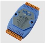
![]() CAN-8123 CANopen Slave Device
CAN-8123 CANopen Slave Device
CAN-8123/ CAN-8223/CAN-8423/CAN-8823
User Guide
Introduction
This user guide introduces the user to how to implement the CAN-8123/CAN-8223/CAN-8423 into their applications in a quick and easy way. Therefore, it only provides the basic instructions. For more detailed information about the CAN-8123/CAN-8223/CAN-8423/CAN-8823, please refer to the CAN-8123/CAN-8223/CAN-8423/CAN-8823 user manual in the product CD or download it from the following website:
http://www.icpdas.com/products/Remote_IO/can_bus/can-8123.htm
or
http://www.icpdas.com/products/Remote_IO/can_bus/can-8423.htm
http://www.icpdas.com/products/Remote_IO/can_bus/can-8823.htm
CAN-8123/CAN-8223 Hardware Structure

CAN-8423/CAN-8823 Hardware Structure

CAN-8123/ CAN-8223 CAN bus connectors ping assignment

| Pin | Signal | Description |
| 1 | CAN GND | Ground (OV) |
| 2 | CAN L | CAN L bus line (dominant low) |
| 3 | CAN_SHLD | Optional CAN Shield |
| 4 | CAN_H | CAN_H bus line (dominant high) |
| 5 | CAN_V+ | CAN external positive supply |
CAN-8423 CAN bus connectors ping assignment

| Pin | Signal | Description |
| 2 | CAN H | CAN_H bus line (dominant high) |
| 3 | CAN SHLD | Optional CAN Shield |
| 4 | CAN_L | CAN L bus line (dominant low) |
CAN-8823 CAN bus connectors ping assignment

| Pin | Signal | Description |
| 2 | CAN _L | CAN_H bus line (dominant high) |
| 5 | CAN SHLD | Optional CAN Shield |
| 7 | CAN_H | CAN _L bus line (dominant low) |
Power and CAN Connection
The CAN-8123/CAN-8223/CAN-8423 CAN connector is a standard 5-pin screw terminal connector. The CAN-8823 CAN connector is D-Sub 9-pin. Users can connect it directly to CAN-8123/CAN-8223/CAN-8423 with any other standard male 5-pin screw terminal and to CAN-8823 with a D-Sub 9-pin connector. Take a note that the CAN-8423 power pin of the CAN connector is useless. Therefore, users need to give CAN-8423 power by using a power connector. Please refer to the CAN-8423 Hardware Structure described before.
Terminal Resistance
In order to minimize the reflection effects on the CAN bus line, the CAN bus line has to be terminated at both ends by two terminal resistances. The CAN-8123/CAN-8223/CAN-8423/CAN-8823 has the 120Ω terminal resistance inside. The JP2 of the CAN-8123/CAN-8223 and the JP1 of the CAN-8423/CAN-8823 are for terminal resistance.
Their position and jumper status are shown in the following figure. 
Install CANopen Slave Utility
Step1: Download the CANopen Slave Utility file from the website http://www.icpdas.com/download/index.htm
or CD-ROM disk following the path:
“/CANopen/Slave/CAN-8×23/Utility/CANopen_SL.exe”
Step 2: Execute the CANopen_SL2.0.exe file to configure the CANopen Slave.
CAN-8123/ CAN-8223 Configuration (Off-line mode)
Step 1: Select “None” in the “COM Port” area. 
Step 2: Take the CAN slave device (CAN-8823 with node ID 1) as an example, Users have to fill in “NODE ID” with 1 and choose “Device Name” with CAN-8823. Then, press the “Next” button. 
Step 3: Then, select a specific device presented in the “Offline Setting” frame, and choose a correct slot module inserted.
For example, if the I-87057 and I-8051 modules are inserted in slot 0 and slot 1 respectively, please select 87057 in the list box, and click “Apply Module” to save the configuration.  Step 4: After finishing the configuration, users can one-left click on the slot module in the “Off-Line Setting” frame if need to change the configuration. If the configuration is successful, users can see the correct module name when the mouse moves in, for example, 87057 on the top of the slot module.
  Step 5: Then, repeat steps 3~4 to configure slot 1 to the I-8042 module. Then, click the “Save Setting” button to finish the offline parameter settings.
  Step 6: Then users can press the button “Create EDS Module” for creating a CANopen slave EDS file.
  Step 7: The two fields, “description” and “create by”, can help users to do some notes in EDS files. If these two fields are empty, the “ICPDAS CANopen I/O Slave Device” and “ICP DAS” will be used as the default value when creating the EDS file.
  Step 8: Users can select the “PDO Info”, then “Device Info“ and the “Module Info” button for the purpose to view the PDO objects, device profile, and slot module configuration information.
These information dialogs are shown below.  If everything is ok, click the “Finish” button to create the EDS file.
  Note: If users use the offline method to get the EDS file, the objects which are used to record the input/output range of the analog modules will be described to the default value in the EDS file. However, the I-87K slot modules hold the input/output range parameter settings in their own EEPROM. It may cause a mismatch between the real input/output range setting and the EDS file. By the way, II-8KCPSx needs to configure the input/output range settings by using the CANopen SDO protocol. For more detail, please refer to section 5.5 in CAN-8123/CAN-8223/ CAN-8423/CAN-8823 user manual.
CAN-8423/CAN-8823 Configuration (On-line mode)
Before using the CAN Slave utility, please make sure that you have connected COM1 of the CAN-8423/CAN-8823 with the available COM port on your PC. The architecture is displayed in the following figure. In this example, the CAN-8423 will be used, and slot modules, I-87057, I-8051, I-8024, and I-8017H are plugged in the slot 0, 1, 2, 3 respectively (If users don’t have any slot module, they can also follow this demo to configure their CAN-8423. But some situation or information relative with slot modules will be a difference). Step 1: Turn off the CAN-8423. Set the “Baud” rotary switch of CAN-8423 to 9 for configuration mode. Then Turn on the CAN-8423.
  Step 2: Use the “ID” rotary switch and “Baud” rotary switch to set the baud rate of CAN-8423. The node ID is useless when the value exceeds the 7F (127 for decimal format) because of the CANopen spec definition. The relationship between the rotary switch value and the practical baud rate is displayed in the following table. Here, use ID 123 and baud rate 1000Kbps for the demo. Therefore, set the “ID” rotary switch to “7B” (7B=7*16+B=112+11=123) and the “Baud” rotary switch to 7.
| Rotary Switch Value | Baud rate (KBPS) |
| 0 | 10 |
| 1 | 20 |
| 2 | 50 |
| 3 | 125 |
| 4 | 250 |
| 5 | 500 |
| 6 | 800 |
| 7 | 1000 |
Step 3: To execute the CAN_SL.exe file, and to display the figure, users have to connect a PC COM port and the CAN-8423 or CAN-8823 well. Here, take the PC COM 1 as an example. Click the “Connect” button to get the information stored in CAN-8823. 
Step 4: Then, users can set the slot information of CAN-8823 in the below “CAN-8×23 Configure” frame. 
Step 5: Please select slot module 3 in the control tab area, and choose the output range in the channel area. Here, take the selection -5.00V~+5.00V as an example. Because of the feature of the I-8017H8 slot module, the output range on each channel will be changed in the same way after users select the output range in one of the channels.  Step 6: After setting the proper output range, users can click the “Set” button to store the configuration. If all of the slot module configurations are finished, click the “Next” button for the next step.
Step 7: Then, the “EDS File Information” window will pop out. Users can fill the “Description” and “Create by” fields for the EDS file. Also, users can see the CANopen objects information and modules information by clicking the buttons.
If the user wants to set dynamic PDO COB-ID, input the COB-ID into the field of the “PDO setting Result” window. 
Then press the button “ Set Dynamic PDO” to store the dynamic PDO COB -ID.  Note1: The CAN-8423/8823 can also create the EDS file by using the off-line mode, and set the analog input range or analog output range by using the CANopen SDO protocol.
Note2: The function, dynamic PDO setting, is only supported in online mode.
Application Procedure
 |
 |
![]()
CAN-8123/CAN-8223/CAN-8423/CAN-8823
Quick Start User Guide
(Ver 4.0 Dec/2012)
Documents / Resources
 |
ICP DAS CAN-8123 CANopen Slave Device [pdf] User Guide CAN-8123, CAN-8223, CAN-8423, CAN-8823, CANopen Slave Device |