![]() 118075EN-02
118075EN-02
2024-05
 CS2500 V2
ART.NO. 118044
QUICK GUIDE
ProNordic
Quick guide
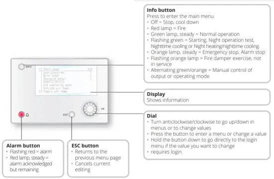
1.1. HMI ProPanel
A central element in the system is the HMI (control panel), where you can adjust settings and take readings.
The control panel consists of an 8-line graphic display, indicator lamps and controls for the settings. Here is a short introduction to the control panel showing how to enter the initial settings in the system.
1.2. Settings
1.1.1. Introduction
Through some simple steps to ensure that the system will function.
If a heating coil has been installed in the ventilation heating coil manual). There is a quick menu for accessing the commonest functions on the control panel,
Language, Timing program and Set point settings.
1.1.2. Select language
To change the language on delivery:
Start page > Quick menu > Commissioning > Language selection Select your preferred language.
1.1.3. Login
In order to make changes to the system, it is normally necessary to log in. There are four authority levels in the system, and three of them are password protected. shown by the number of keys in the top left hand corner of the display. The menus show more options or fewer, depending on the level at which you are logged in.
The following key symbols will be used from now on in the manual to describe the login level before the editable. The same key symbols are shown at the top levels:
Level 1: No restrictions, no password required.
- Read access to all menus except system
- Read access to alarm lists and alarm history.
Level 2: End user, password 1000.
One key symbol ![]()
- All rights as for level 1, plus:
- Write access to the most important setpoints (Setpoints/Settings > Setpoints).
- Alarms and alarm history can be acknowledged and reset.
Level 3: System administrator, password 2000.
Two key symbol ![]()
- All rights as for level 2, plus:
- Rights to all menus except I/O configuration and system settings.
Level 4: OEM, password given only in consultation with the Flexit service organisation.
Three key symbol ![]()
- All rights as for level 3, plus:
- Rights to all menus and system settings.
Start page > Main menu > Enter PIN
1.1.4. Set time/time channels
![]() Start page > Quick menu > SetUp > Date/ Time Input
Start page > Quick menu > SetUp > Date/ Time Input
1.1.5. Set the calendar and timing program
![]() Start page > Quick menu > SetUp >Timeswitch program
Start page > Quick menu > SetUp >Timeswitch program
General
This section describes functions and settings for the timing program and calendars.
When no object with higher priority (for example Manual control <> Auto) is activated, the system can be switched off or the steps changed via the timing program.
A maximum of six switch-over times can be specified per day.
The calendar stop overrides the calendar exception, which in turn overrides the normal timing program (only in Operating mode). Up to 10 periods or exception days can be specified for each calendar.
![]() NB. Both setpoints for fan steps and temperature setpoints (comfort /economy) are controlled by the timing program.
NB. Both setpoints for fan steps and temperature setpoints (comfort /economy) are controlled by the timing program.
1.1.6. Week schedule
| Parameter | Value | Function |
| Present value | — | Switch-over according to schedule |
| Monday | Shows current command when the current day is Monday. The latest time that can be entered for a day is 23:59. Go to the daily switch-over schedule for Mondays. |
|
| Copy schedule | -Mo -Tu-Fr -Tu-Su -Tu -We -Th -Fr – Sa -Su -Ecpt | Copies times for the timing program from Monday to Tuesday-Friday/Tuesday-Sunday. -Passive (no copying). -Copying starts. Return to the display screen. Exception |
| Tuesday | Same function as for Monday. | |
| … | ||
| Sunday | Same function as for Monday. | |
| Exception | Shows current command when the current day is an exception day. Go to the daily switch-over schedule for exception days. |
|
| Period: Start | (Only Authority level 3.) Start date for weekly schedule. *,**. 00 means that the weekly schedule is always activated. —> Activate weekly schedule. | |
| Period: End | (Only Authority level 3.) Start date and time for disabling of weekly schedule. |
1.1.7. Day schedule
| Parameter | Value | Function |
| Present value | — | Switch-over according to the schedule when the current weekday is the same as the switch-over day |
| Day schedule | Status for current week or exception day: -Current weekday (system day) is not the same as the switch-over day. -Current weekday (system day) is the same as the switch-over day. |
|
| Time-1 | This is locked to 00:00 | |
| Value-1 | Eco.St1 Comf.St1 Eco.St2 Comf.St2 Eco.St3 Comf.St3 |
Indicates the unit’s operating mode when Time-1 occurs |
| Time-2 | 00:0123:59 | Switch-over time 2. *:* —> Time inactivated |
| Value-2 … Value-6 |
Eco.St1 Comf.St1 Eco.St2 Comf.St2 Eco.St3 Comf.St3 |
Indicates the unit’s operating mode when Time-2 occurs |
| Time-3 Time-6 |
00:0123:59 | Switch-over time 3-6. *:* —> Time deactivated |
1.1.8. Calendar (exceptions and stop)
Exception days can be defined in the calendar.
These can include specific days, periods or weekdays.
Exception days override the weekly schedule.
Calendar exceptions
Switch-over follows the weekly schedule and the exceptions specified in the daily schedule when a switch-over time is activated in the calendar exception.
Calendar stop
The system is turned off when the calendar stop is activated.
Parameter:
![]() Start page > Quick menu > SetUp >
Start page > Quick menu > SetUp >
Timeswitch program > Calendar execption
![]() Start page > Quick menu > SetUp > Timeswitch program > Calendar fix off
Start page > Quick menu > SetUp > Timeswitch program > Calendar fix off
| Parameter | Value | Function |
| Current value | -Passive -Active |
Shows whether a calendar time is activated: – No calendar time activated – Calendar time activated |
| Selection -x | -Date -Interval -Weekday -Passive |
-A certain day (e.g. 1 May) -A period (e.g. holiday) -A certain weekday -Times are deactivated This value must always be placed last, after the date |
| (Start) Date | – Selection-x = interval: Enter the start date for the period date) | |
| End date | -Selection-x = interval: Enter the end date for the period The end date must be later than the start date |
|
| Weekday | -Selection-x = only weekdays: Enter a weekday. |
Example: Selection-x = Date
Only the time for (start) is relevant.
- (Start)Date = *,01.01.16
Result: 1 January 2016 is an exception date. - (Start)Date = Mo,*.*.00
Every Monday is an exception day - (Start)Date = *,*.Even.00
All days in even months (February, April, June, August, etc.) are exception days.
Example: Selection-1 = interval
The times for (Start)Date and End date are adjusted.
- (Start)Date = *,23.06.16 / -End date = *,12.07.16. 23 June 2016 until end of 12 July 2016 are exception days (for example holidays).
- (Start)Date = *,23.12.16 / End date = *,31.12.16 23-31 December are exception days every year. Time End date = *,01.01.16 will not work, because 1 January comes before 23 December.
- (Start)Date = *,23.12.16 / -End date = *,01.01.17. 23 December 2016 up to and including 1 January 2017 are exception days.
- (Start)Date = *,*.*.17 / -End date = *,*.*.17
Warning! This means that the exception is always active!
Example: Selection-1 = Weekday
Selection-1 = Weekday
The times for weekdays are adjusted.
- Weekday = *,Fr,*
Every Friday is an exception day. - Weekday = *,Fr,Even
Every Friday in even months (February, April, June, August, etc.) is an exception day. - Weekday = *,*,*
Warning! This means that the exception is always active!
1.3. Adjust setpoints for speeds and temperatures
![]() Start page > Quick menu > Settings > Setpoints/Settings
Start page > Quick menu > Settings > Setpoints/Settings
| Parameter | Function |
| All settings | > |
| Comfort htg stpt | Indicates the temperature setpoint for comfort operation (daily operation) |
| Economy htg stpt | Indicates the temperature setpoint for economy operation (nighttime setback) |
| Sply fan st 1 stpt | Indicates the supply airflow step 1 |
| Sply fan st 2 stpt | Indicates the supply airflow step 2 |
| Sply fan st 3 stpt | Indicates the supply airflow step 3 |
| Sply fan st 4 stpt | Indicates the supply airflow step 4 |
| Sply fan st 5 stpt | Indicates the supply airflow step 5 |
| Extr fan st 1 stpt | Indicates the extract airflow step 1 |
| Extr fan st 2 stpt | Indicates the extract airflow step 2 |
| Extr fan st 3 stpt | Indicates the extract airflow step 3 |
| Extr fan st 4 stpt | Indicates the extract airflow step 4 |
| Extr fan st 5 stpt | Indicates the extract airflow step 5 |
1.4. Service switch
The service switch is used to stop the unit for servicing.
NB. If the electric coil was active when the unit was turned off, there will be 180 seconds run-on time before the unit stops cooling the coil.
![]() Start page > SERVICE SWITCH
Start page > SERVICE SWITCH
| Parameter | Function |
| Auto | The unit is controlled via time channel |
| Off | Service mode, the unit is stationary |
1.5. Extract air regulation
As standard, the unit is configured to regulate the temperature via the supply air, but can easily be configured to regulate this via the extract air instead.
To do this, go into the following menu:
![]() Start page > Main menu > Configuration > Configuration 1 > Tmp control mode
Start page > Main menu > Configuration > Configuration 1 > Tmp control mode
| Parameter | Function |
| Supply | Temperature regulation is controlled by the supply air temperature |
| ExtrSplyC | Temperature regulation is controlled as a function of the extract and supply air sensors and maintains the set extract air temperature After making a change in a configuration menu, RESTART. |
![]() Start page > Main menu > Configuration > Configuration 1 > Restart required! > Execute
Start page > Main menu > Configuration > Configuration 1 > Restart required! > Execute
![]()
To adjust limitations to the inlet temperature in the case of extract air regulation.
![]() Start page > Quick menu > Settings > Setpoints/Settings
Start page > Quick menu > Settings > Setpoints/Settings
| Parameter | Function |
| Supply tmp min | Indicates the lowest permitted supply air temperature |
| Supply tmp max | Indicates the highest permitted supply air temperature, |
1.6. Changing the flow display units
The standard setting for the unit is m*/h, but can easily be changed to I/s. When the units are changed, the setpoint values for airflow are automatically recalculated.
![]() Start page > Main menu > Configuration > Configuration 2 > Flow display
Start page > Main menu > Configuration > Configuration 2 > Flow display
| Parameter | Function |
| No | Not used |
| l/s | Shows the airflow in I/s |
| m3 /h | Shows the airflow in m?/n |
After making a change in a configuration menu, RESTART.
![]() Start page > Main menu > Configuration > Configuration 2 > Restart required! > Execute
Start page > Main menu > Configuration > Configuration 2 > Restart required! > Execute
1.7. Alarm handling
![]()
If an alarm has been triggered, it will be shown by the flashing alarm symbol. You can get more information by pressing the alarm button. To reset the alarm, press the alarm button twice and select ‘Confirm/Reset ‘ and then Execute in the menu.
Flexit AS, Moseveien 8, N-1870 Ørje
www.flexit.com
Documents / Resources
 |
FLEXIT CS2500 V2 Automatic Control [pdf] User Guide CS2500 V2, 118044, CS2500 V2 Automatic Control, CS2500 V2, Automatic Control, Control |


