FAS IP20 EtherCAT Bus Module
PRODUCT INSTRUCTION
- Ordering code: 009E93
- Part number: FNI ECT-116-104-D64
- Module Type: EtherCAT IP20 bus module
- Features: 64 DI/DO PNP adaptive
Product Usage Instructions
Installation and Start-up:
Ensure proper corrosion resistance measures are taken as per the precautions mentioned in the manual before installation. Disconnect all power sources before starting the installation process.
Mechanical Connection:
The module can be installed using either 4 M4 bolts or DIN35 rail snaps for secure mounting.
Electrical Connection:
Connect the power interface as per the following pin configuration:
| Pin | Function |
|---|---|
| 1 | UA: +24V (Brown), GND 0V (White) |
| 2 | US: +24V (Blue), GND 0V (Black) |
- It is recommended to provide separate power supplies for US and UA. Ensure the total current of UA power supply is within specified limits.
Security
Expected use
- This manual describes as decentralized input and output modules for connecting to an indstrial network.
Installation and start-up
Precautions!
- Installation and start-up may only be performed by trained personnel. A qualified individual is one who is familiar with the installation and operation of the product and has the necessary qualifications to perform such operations. Any damage caused by unauthorized operation or illegal and improper use is not covered by the manufacturer’s warranty. The equipment operator is responsible for ensuring that appropriate safety and accident prevention regulations are observed.
Corrosion resistance Precautions!
- FNI modules generally have good chemical and oil resistance.When used in corrosive media (e.g. high concentrations of chemicals, oils, lubricants, coolants and other material media (i.e. very low water content), these media must be checked before the corresponding application material compatibility.If a module fails or is damaged due to this corrosive medium, a defect claim cannot be made.
Dangerous voltage
- Precautions!
- Disconnect all power before using the device!
- General security
| Debugging and inspection | Fault | Owner/operator obligations | Expected use |
| Before debugging, read the user manual carefully. | If the defect or equipment failure cannot be corrected, the operation
of the equipment must be stopped to avoid damage that may be caused by unauthorized use. |
This equipment is an EMC Class A compliant product. This device produces RF noise. | The warranty and limited liability statement provided by the manufacturer does not cover damage caused by:
·Unauthorized tampering ·Improper use operation ·The instructions provided in the user manual explain the use, installation and handling of discrepancies |
| This system cannot be used in an environment where the safety of personnel depends on the functionality of the equipment. | Only after the housing is fully installed can the intended use be assured. | The owner/operator must take appropriate precautions to use this
equipment. |
|
| This device can only use the power supply that matches this device, and can only connect cables approved
for application. |
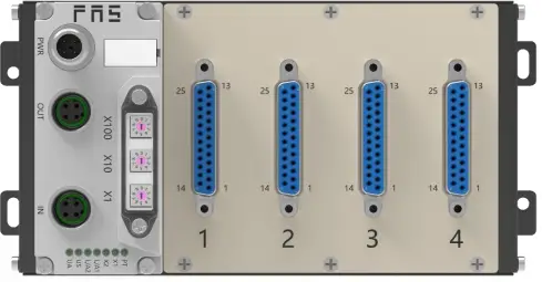
Introduction

- Power supply interface
- EtherCAT output
- DIP switch
- EtherCAT input port
- Module status indicator light
- Channel 1
- Channel 2
- Channel 3
- Channel 4
Mechanical connection
- The module is installed using 4 M4 bolts or DIN35 rail snaps.
Electrical connection
Power interface (A-coded)
Illustrate:
- It is recommended to provide Us a power supply and a UA power supply separately;
- The total current of UA power supply is <4A, and the total current of Us power supply is <4A;
- The FE connection from the housing to the machine must be low impedance and kept as short as possible

Illustrate:
Unused I/O port sockets must be covered with end caps to meet IP67 protection rating
Signal port (D-SUB 25, female socket)
Illustrate:
- Input signal type support: three-wire PNP, two-wire PNP, dry contact;
- Pin +24V single output current maximum 350mA. The total module current is <4A;
- The total current of each 8 channels does not exceed 1A.
Module wiring method
- In independent power supply mode, the maximum current of each module can reach 4A.
TECHNICAL DATA
SIZE
Mechanical data
| Shell material | Aluminum shell |
| Housing rating according to IEC 60529 | IP20 |
| Power interface | A-Coded |
| Input port/output port | DUSB-25 |
| Size(W*H*D) | 183.5mm*92mm*50.1mm |
| Installation type | Screw fixing or DIN35 rail mounting |
| Weight | About 670g |
Operating conditions
| Operating temperature | -5°C | ~ | 80°C | ||
| Storage temperature | -25°C | ~ | 85°C | ||
Electrical data
| Voltage | 18~30V DC,conform to EN61131-2 |
| Voltage fluctuation | <1% |
| Input current when power supply voltage is
24V |
<130mA |
| Maximum load current, sensor/channel | 1 A |
| Maximum load current, actuator | 0.5A |
| Total current Us | ≤4A |
| Total current Ua | ≤4A |
Network port
| Port | 2 x 10Base-/100Base-Tx |
| Port connection | M12,D-Coded |
| IEEE 802.3 compliant cable types | Shielded twisted pair, minimum STP CAT
5/STP CAT 5e |
| Data transfer rate | 10/100 Mbit/s |
| Maximum cable length | 100m |
| Flow control | Half working condition/full working
condition (IEEE 802.3-PAUSE) |
Function indicator

| LED | Show | Function |
| PT | Blue | EtherCAT protocol |
| X1 | Closure | No error, device initializing |
| Green light flashes 2.5HZ | Pre-operation: The device is in pre-operation state | |
| Green light flashes 1HZ | Safe operation: The equipment is in safe operation. | |
| Green constant | Running: The device is running | |
| X2 | Closure | No errors, device EtherCAT communication is
working |
| Red light flashes 2.5HZ | Invalid configuration | |
| Red light flashes 1HZ | local error | |
| Red light double flash | Application monitoring timeout | |
| L/A1 | Steady green | Device (IN) connected to Ethernet |
| Yellow light flashes | Device (IN) sends/receives Ethernet frames | |
| Closure | Device (IN) is not connected to Ethernet | |
| L/A2 | Steady green | Device (OUT) connected to Ethernet |
| Yellow light flashes | Device (OUT) sends/receives Ethernet frames | |
| Closure | Device (OUT) is not connected to Ethernet | |
| US | Green | Input voltage is normal |
| Flashing red | Input voltage low (< 18 V) | |
| UA | Green | Output voltage is normal |
| Flashing red | Output voltage low (< 18 V) | |
| Red always on | No output voltage present (< 11 V) |
INTEGRATED
Module configuration
Restore factory settings
Steps:
- When the device is powered off, dial 900;
- Power on the device and wait 10 seconds;
- Power off the device and dial the code to the state before setting;
- Power on the device and restore it to factory status;
Node address configuration
- The node address is assigned by the PLC: the dialing address X100=4 X10=0 X1=0, the node number is set in the PLC;
- Manual allocation of node address: Dial address X100=4, node number is X10=tens digit X1=units digit
Example:
Dial code: X100=4, X10=2, X1=5
The node number is 25
Note that the maximum node number is 99. After dialing adjustment, you need to power on again;
Data mapping
- Digital Output Mapping_Standard Output 01-08_3000_01: Channel 1~8 output signal mapping
- Digital Output Mapping_Standard Output 09-16_6000_02: Channel 9~16 output signal mapping
- Digital Output Mapping_Standard Output 01-08_3000_01: Channel 1~8 output signal mapping
- Digital Output Mapping_Standard Output 09-16_6000_02: Channel 9~16 output signal mapping
PLC integration tutorial
Omron NX1P2 Sysmac Studio integration (ECT)
- Create a new project and determine the device type, device and hardware version, which can be obtained from the PLC side

- Click EtherCAT, pop up the main device and click Show ESI Library in the drop-down menu displayed by right-clicking

- Click the installation file;

- Open the ESI configuration file downloaded in advance from the official website: FAS FNI ECT-116-104-D64 ECS V5.0.0.xml, and confirm;

- Find the FAS FieldBus Modules in the toolbox on the right and double-click the module model icon to join the network

- Click IO variable mapping, select the added node in the I/O mapping, and fill in the name of the variable

- Click the PLC online mode button. The configuration interface shows that the controller status is offline. Then right-click the master device and write the device node address. Note that the node address needs to be consistent with the previous EtherCAT slave device;

- Find the controller in the menu bar, transfer it to the controller, download it to the PLC, and agree to confirm;

- PLC is online, the output terminal value is set to 1, the value displays TRUE and turns orange,and the corresponding signal light of the slave device lights up

Appendix
Ordering information
| Product ordering code | Ordering code |
| FNI ECT-116-104-D64 | 009E93 |
More info
- Telephone: 0591-22991876
- Technical support: +86 13306936805
- Official website: www.faselec.com

- Business support: +86 19905006938
- Address: Room 009, A1, Building 1, National University Science and Technology Park Science and Technology Innovation Center, No. 6 Qiuyang East Road, Shangile Town. Minhou County. Fujian Province.
- Technical support

FAQ
- Q: What should I do if the module is exposed to corrosive media?
- A: Check the compatibility of the media with the module material before usage. Failure due to corrosive media may void warranty claims.
- Q: How should I handle dangerous voltage situations?
- A: Always disconnect all power sources before using the device to avoid accidents.
- Q: What precautions should I take for debugging and inspection?
- A: Read the user manual thoroughly before debugging. Do not use the equipment in environments where personnel safety depends on its functionality.
Documents / Resources
 |
FAS IP20 EtherCAT Bus Module [pdf] User Manual 009E93, FNIECT-116-104-D64, IP20 EtherCAT Bus Module, IP20, EtherCAT Bus Module, Bus Module, Module |