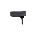
ENCELIUM WCM Wireless Control Module

Product Specifications
- Product Name: WCM
- Models: WCM
- Installation: Dry, indoor locations only
- Recommended Use: Electronic dimming, non-dimming, HID, etc., ballasts or LED drivers
Product Usage Instructions
Mounting Options
- Option 1 — Luminaire Mount: Install the module in a PG-7 (0.5 inch) trade-size knockout on top or side of a luminaire.
- Option 2 — Junction Box Mount: Securely mount the WCM to a junction box using an available PG-7 (0.5 inch) trade-size knockout and retainer nut.
Electrical Connections
- Luminaire Wiring: GreenBus communication wiring is accessible from the outside of the luminaire. The WCM dimming interface (purple and pink wires) is a galvanically isolated 0-10V circuit, wired as NEC Class 1 or 2. Parallel all ballast input wires for controlling multiple ballasts.
- GreenBus Port: Can be used when wiring to a luminaire. Power feed specifications: LINE – BLACK, NEUTRAL – WHITE, RED – PURPLE, PINK – BLUE. Control & Power Wires recommended relay switching capacity: 120-347V, 300VA maximum.
FAQ
- Can the WCM be used in damp locations?
The WCM is to be installed in dry, indoor locations ONLY. For damp installations, ensure to use the appropriately rated version of the WCM Module as per the Models section of the manual. - What safety precautions should be followed when using the product?
When using electrical equipment like the WCM, follow basic safety precautions such as not mounting near gas or electric heaters, ensuring equipment is not tampered with by unauthorized personnel, and using the product only for its intended purpose.
PRODUCT SAFETY
When using electrical equipment, basic safety precautions should always be followed, including the following:
READ THESE INSTRUCTIONS BEFORE USING THIS PRODUCT.
- Do not mount near gas or electric heaters.
- Equipment should be mounted in locations and at heights where it will not readily be subjected to tampering by unauthorized personnel.
- The use of accessory equipment is not recommended by Encelium as it may cause an unsafe condition.
- Do not use this equipment for other than the intended use.
SAVE THESE INSTRUCTIONS.
GETTING STARTED
Overview
- The Wireless Control Module (WCM) allows luminaires and occupancy sensors to communicate via a mesh network based on Zigbee® standards. Individually addressable, the WCM enables each ballast or LED driver to be independently controlled and configured.
- The WCM is available in two models:
- Indoor
- Damp Rated
WIRELESS SYSTEM OVERVIEW
This illustration shows how each component is easily integrated into the Encelium X Lighting Control System.

INSTALLATION
In a typical installation, the WCM connects to electronic dimming, non-dimming, HID, etc., ballasts or LED drivers to make each individual device controllable by the Encelium X Lighting Control Systems.
Notes: The WCM is to be installed in dry, indoor locations ONLY. For damp installations, ensure to use the appropriately rated version of the WCM Module (see Models section of this manual). Damp locations are defined as: interior locations subject to moderate degrees of moisture, such as some basements, some barns, some cold-storage warehouses, and the like, and partially protected locations under canopies, marquees, roofed open porches, and the like.
MOUNTING OPTIONS
Option 1 —Luminaire Mount
The mechanical construction allows for simple installation of the module in an available PG-7 (0.5 inch) trade-size knockout on top or side of a luminaire.

Option 2—Junction Box Mount
For some installations, a junction box may be required. It is recommended to securely mount the WCM to the junction box using an available PG-7 (0.5 inch) trade-size knockout and retainer nut.

ELECTRICAL CONNECTIONS
Luminaire Wiring
- GreenBus communication wiring is still accessible from the outside of the luminaire, while all necessary wiring to the electronic dimming ballast is available on the inside. The WCM dimming interface (purple and pink wires) is a galvanically isolated 0-10V circuit such that it may be wired as NEC Class 1 or 2.
- The module has been tested in accordance to UL2043 and is suitable to be used in plenum or “plenum rated” areas. All wiring is rated 600V, 105ºC (221ºF) for use in luminaires. The black and red wires connect to the internal relay and allow the module to interrupt power to the load for complete shutoff. Refer to local electrical code, etc.
- To control multiple ballasts, parallel all ballast input wires (line, neutral, and control wires purple and pink). It is recommended to observe the maximum ratings of the WCM to ensure maximum ratings are not exceeded.

- Recommended relay switching capacity, 120-347V, 300VA maximum.
- Due to the internal relay, power feed to the luminaire may be live even if lights are off. Turn off power at circuit breaker or fuse before installing or servicing module. Observe lockout procedures.
- GreenBus uses proprietary connectors and jacks for ease of installation only. GreenBus is a proprietary standard. Connect to Encelium X Lighting Control System only. Do not connect to other circuits.
Non-Dimmable Luminaire Wiring
Connect line voltage AC power to WCM and ballasts.

Dimmable Luminaire Wiring
Connect line voltage AC power to WCM and ballasts. Dimming wires (Purple and Pink) from WCM can be run either as Class 1 or Class 2 (consult applicable local electrical and building codes).

WCM to LCM Wiring

WCM to SIM Wiring

WCM Emergency Lighting Wiring

WCM to LCM Emergency Lighting Wiring

Class 1 and Class 2 Wiring
The WCM may be wired as a Class 1 or a Class 2 device on the blue, purple, and pink wires. If these wires are connected to a Class 1 signal, ensure to install the provided cap over the GreenBus connector. To remove the GreenBus cap, insert a flat screwdriver beneath the pry portion of the cap and pry outward until the cap slides out.

Failure to install black cap for Class 1 wiring schemes may result in exposed hazardous voltages at the GreenBus adapter.
GreenBus
- The GreenBus wiring originates at the WCM and supports a single GreenBus device to be connected per WCM.
- The GreenBus wires must be used with proprietary connectors supplied. Insert the connectors to the WCM GB ports.
- GreenBus must be laid out as per supplied system layout drawing. If changes are required, determine an optimum wiring path utilizing the supplied cables, based on the position of the devices

- To remove the wires, use a flat head screwdriver to release the wires from the terminal blocks.

- GreenBus must be laid out as per supplied system layout drawing. If changes are required, determine an optimum wiring path utilizing the supplied cables, based on the position of the devices
EMERGENCY LIGHTING
Central Power Sense, Stand-Alone WCM
Mains Connection
- WCM is connected to a branch circuit that is connected to back-up power circuit.
- The Encelium X Wireless Manager is NOT connected to emergency back-up power.
Condition Prior to Emergency
Luminaire is functioning normally.
Emergency Condition
- WCM loses normal power when power outage occurs.
- Emergency/back-up power system is initiated via central sense or switchgear.
Emergency Behavior
WCM regains power feed when back-up power comes on. It releases the dimming control and turns on the internal relay to pass back-up power to the emergency luminaire.
Note: The WCM will begin dimming again when the Wireless Manager comes back online.
Local Power Sense, WCM with LCM
Mains Connection
- WCM is NOT connected to an emergency back-up power branch circuit. The WCM detects power loss in this configuration (“local sense”).
- The Encelium X Wireless Manager is NOT connected to emergency back-up power.
- Luminaire Control Module (LCM) is connected to a branch circuit that is connected to back-up power.
Condition Prior to Emergency
Luminaire is dim (or off).
Emergency Condition
WCM and GreenBus Luminaire Control Module (UL924 recognized) loses power when power outage occurs.
Emergency Behavior
- GreenBus Luminaire Control Module regains power feed when backup power comes on.
- WCM does NOT regain power feed because it is not connected to an emergency back-up power branch circuit.
- The GreenBus Communication Bus is released allowing the GreenBus Luminaire Control Module to release dimming control and turn on the internal relay to pass backup power to the emergency luminaire.
Note: The WCM and GreenBus Luminaire Control Module will begin dimming again when the normal power is restored.
Documents / Resources
 |
ENCELIUM WCM Wireless Control Module [pdf] Instruction Manual WCM Wireless Control Module, WCM, Wireless Control Module, Control Module, Module |