
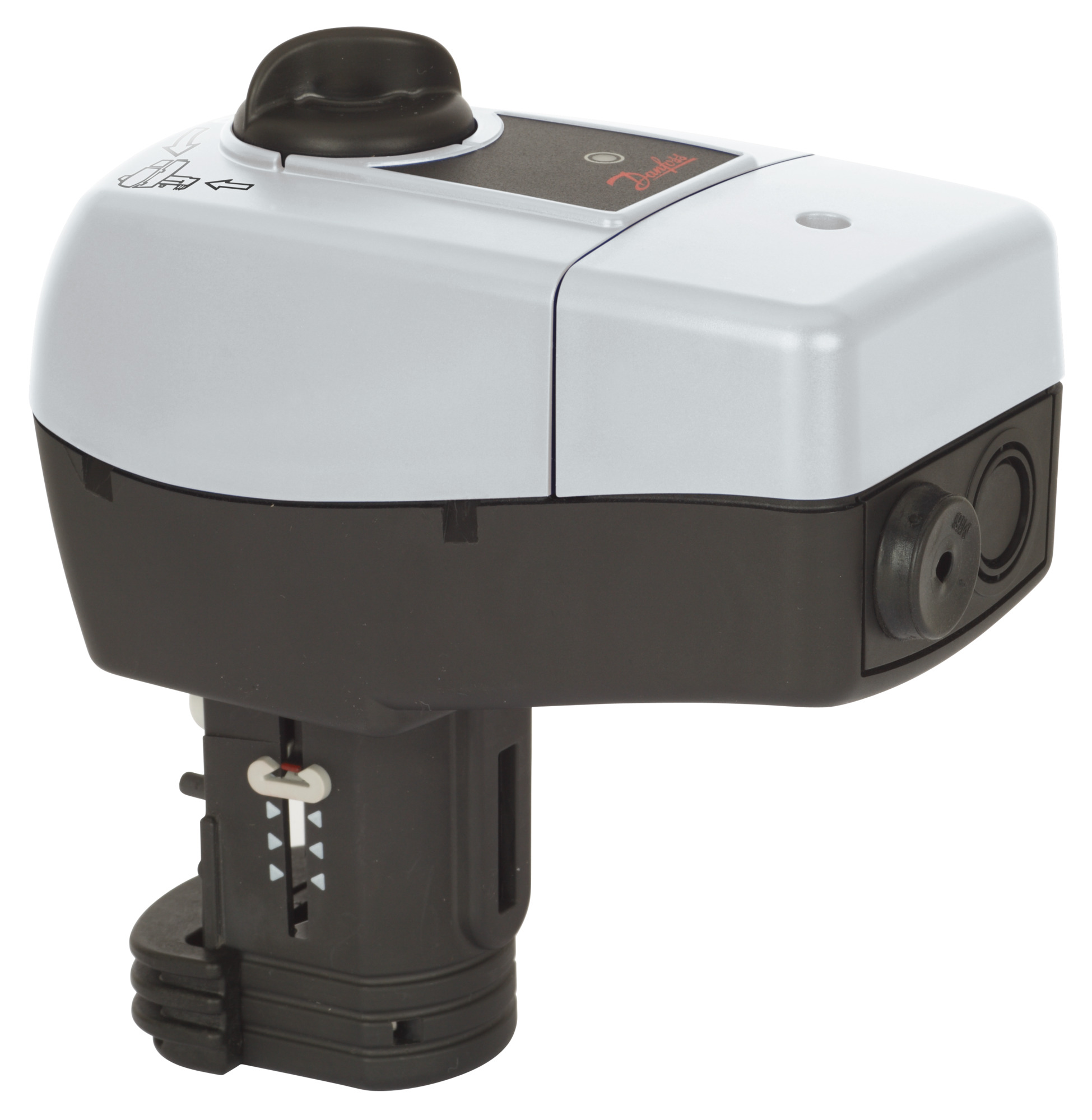
Danfoss AME 11 Electrical Actuator
Specifications
- Model: AME 10, AME 11
- Maintenance: Maintenance Free
- Operating Conditions: 5-95% RH, no condensing
- Protection Rating: IP 54
- Wiring: A, B, Neutral Power supply
- Supply Voltage: 24 V~ -15 to +10%, 50/60 Hz
Product Usage Instructions
Mounting:
Fix the actuator on the valve.
Wiring:
- Control Signal: Connect the control signal from the controller to terminals Y (input signal) and SN (common) on the AME printed board.
- Output Signal: Use the output signal from terminal X for an indication of the current position. The range depends on the DIP switch settings.
Supply Voltage:
Connect the supply voltage (24 V~ -15 to +10%, 50/60 Hz) to the SN and SP terminals.
FAQ
- Q: What should I do to avoid injury and device damage?
- A: Read and observe all safety notes carefully. Assembly, start-up, and maintenance should be done by qualified personnel only.
- Q: How should I dispose of the product?
- A: Dismantle the product and sort its components for recycling or disposal following local regulations.
Models

Tools

Safety Notes
To avoid injury of persons and damages to the device, it is absolutely necessary to read and observe these instructions carefully. Necessary assembly, start-up, and maintenance work must be performed by qualified and authorized personnel only. Please comply with the instructions of the system manufacturer or system operator.
Disposal instruction
This product should be dismantled and its components sorted, if possible, in various groups before recycling or disposal.
Always follow the local disposal regulations.
Mounting
Fix the actuator on the valve.


Wiring


Control signal
Control signal from the controller must be connected to terminals Y (input signal) and SN (common) on the AME printed board.
Output signal
Output signal from the terminal X can be used for indication of the current position. Range depends on the DIP switch settings.
Supply voltage
Supply voltage (24 V~ −15 to +10 %, 50/60 Hz) must be connected to the terminals SN and SP.
DIP switch settings 


Factory settings:
ALL switches are on OFF position! ①
Note: All combinations of DIP switches are allowed. All functions that are selected are added consecutively. There is only one logic override of functionalities i.e. the switch No.6 Proportional / 3 point, which sets actuator to ignore control signal and works as a “simple” 3-point actuator.
SW1: U/I ②
The actuator can responde to a voltage or current control signal. With switch No.1: U/I actuator can be set either to operate with a voltage control signal (actuator responds to signal between 0-10 V), or current control signal (actuator responds to signal between 0-20 mA).
Factory setting: voltage control signal (0-10 V).
SW2: 2 V-10 / 0 V-10 ③
The actuator can be set to respond on a control signal from 2 V, or 0 V. If the actuator is set current signal then it responds to a control signal from 4 mA or 0 mA.
Factory setting is: 2-10 V.
SW3: Direct/Inverse ④
The actuator can be set for spindle to travel downwards on rising control signal (DIRECT), OR for the spindle to travel upwards on rising control signal (INVERSE).
Factory setting is: DIRECT
SW4: —/Sequential ⑤
Two actuators can be set to work parallel withone control signal. If the SEQUENTIAL is set then an actuator responds to split control signal (see 0(2)-5(6) V/ 6(6)-10 V).
Note: This combination works in combination with switch No.5: 0(2)-5(6) V/ 6(6)-10 V
SW5: 0(2)-5(6) V/6(6)-10 V ⑥
Note: This function is available if switch No.4:
— / Sequential is set.
SW6: Proportional/3 point ⑦
Actuator needs to perform Self stroking prior to changing DIP 6 to ON. Output signal depends on DIP 2, and 3&5 setting. Actuator can operate in modulating (DIP 6 to OFF) or in “simple” 3-point mode, if the 3-point function is selected (DIP 6 to ON).Connect power supply on terminals SN and SP terminals. Factory set DIP 6 to OFF for operating actuator in Modulating mode. Actuator’s stem will run to its totally extended or retracted position by bridging SN signal to terminals 1 or 3 and will remain in this positron as long as potential is present. Set DIP 6 to ON for operating the actuator in 3-point mode. Look carefully wiring diagram as wiring is different for controllers with triac output (ECL) in comparison to controllers with relay output. Return signal X indicates the correct position. Note: If the 3-point function is selected actuator does not respond to any control signal on port Y. It only rises and lowers spindle if power is supplied on port 1 or 3.
SW7: LOG/LIN – Not in use.
SW8: 100 % kVS/Reduced kVS – Not in use.
SW9: Reset ⑧
After the actuator has been connected to the power supply, the actuator will start the self-adjustment procedure. The indicator LED flashes until self-adjustment is finished. The duration depends on the spindle travel and will normally last a few minutes. The stroke lengthof the valve is stored in the memory after self-adjustment has been completed. To restart self-adjustment, change the position of RESET switch (switch No. 9). If the supply voltage is switched off or falls below 80 % in more than 0.1 s, the current valve position will be stored in the memory and all data remain saved in thememory also after a power supply cut-out.
Function test
The indicator light shows whether the positioner is in operation or not. Moreover, the indicator shows the control status and faults.
Constant light
- normal operation
No light
- no operation or no power supply
Intermittent light (1 Hz)
- self adjusting-mode
Intermittent light (3 Hz):
- power supply too low
- insufficient valve stroke (<20 s)
- end-position cannot be reached.
Dimensions
|
DN |
H
1 |
H
2 |
H
3 |
H
4 |
| mm | ||||
| 15 | 163 | – | 159 | 192 |
| 20 | 163 | 149 | 159 | 192 |
| 25 | 163 | 155 | 164 | 192 |
| 32 | – | 169 | – | |
| 40 | – | – | 174 | – |
|
Part Name |
Hazardous Substances Table | |||||
| Lead (Pb) | Mercury (Hg) | Cadmium (Cd) | Hexavalent Chromium (Cr(VI)) | Polybrominated biphenyls (PBB) | Polybrominated diphenyl ethers (PBDE) | |
| Plug | X | O | O | O | O | O |
| Bush | X | O | O | O | O | O |
| O: Indicates that this hazardous substance contained in all of the homogeneous material for this part is below the limit requirement in GB/T 26572; | ||||||
| X: Indicates that this hazardous substance contained in at least one of the homogeneous materials for this part is above the limit requirement in GB/T 26572; | ||||||
Danfoss A/S
- Climate Solutions
- danfoss.com
- +45 7488 2222
Any information, including, but not limited to information on selection of product, its application or use, product design, weight, dimensions, capacity or any other technical data in product manuals, catalogs descriptions, advertisements, etc. and whether made available in writing, orally, electronically, online or via download, shall be considered informative, and is only binding if and to the extent, explicit reference is made in a quotation or order confirmation. Danfoss cannot accept any responsibility for possible errors in catalogues, brochures, videos and other material Danfoss reserves the right to alter its products without notice. This also applies to products ordered but not delivered provided that such alterations can be made without changes to form, fit or function of the product.
All trademarks in this material are property of Danfoss A/S or Danfoss group companies. Danfoss and the Danfoss logo are trademarks of Danfoss A/S. All rights reserved.
Documents / Resources
 |
Danfoss AME 11 Electrical Actuator [pdf] User Guide AME 11 Electrical Actuator, AME 11, Electrical Actuator, Actuator |