COMMAND ACCESS MLRK1-CAL Field Installable Motorized Latch Retraction Kit
INSTRUCTION MANUAL
The Command Access MLRK1 is a field installable motorized latch-retraction kit for:
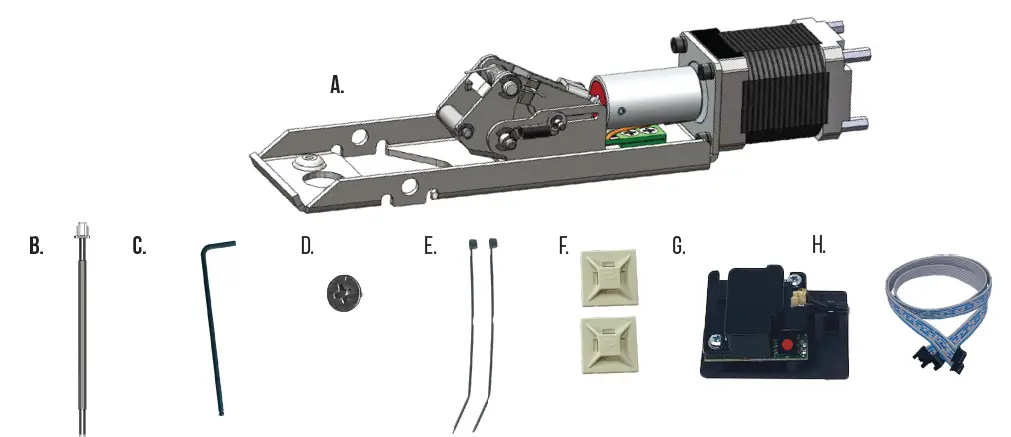
Kit Includes
A. 1- Motor Mount
B. 1- 50944 – Molex Pigtail
C. 1- 10017 5/64″ Allen wrench
D. 2- 40801 – Phillips Screws
E. 2- 40060 – cable tie
F. 2- 40059 – mounting pad
G. 1- 60373/51186 – remote mm5 module
H. 1 – 51198 – remote module cable

Recommended Power Supplies: Use a power limited class 2 power supply
All Command Access exit devices & field installable kits have been thoroughly cycle tested with Command Access power supplies at our factory. If you plan on using a non-Command power supply it must be a filtered & regulated linear power supply
Technical Information

Setting PUSH TO SET (PTS)
Make sure to set PTS before finishing installation

Step 1 – To enter PTS mode: Depress MM5 button & apply power. The device will emit 1 SHORT beep. The device is now in PTS mode.
Step 2 – While depressing the push pad, apply power. (i.e. presenting the credential to the reader).
Step 3 – Continue to keep pad depressed, the device will emit 1 LONG Beep. After the beep has stopped, release the pad and now the adjustment is complete. test the new location, If not to your liking repeat the 3 steps.
Troubleshooting & Diagnostics
| Beeps | Explanation | Solution | |||||||||||
| 2 Beeps | Over Voltage | > 30V unit will shut down. Check voltage & adjust to 24 V. | |||||||||||
| 3 Beeps | Under Voltage | < 20V unit will shut down. Check voltage & adjust to 24 V. | |||||||||||
| 4 Beeps | Failed Sensor | Verify all 3 sensor wires are installed correctly. Replace sensor if problem persists by contacting office. | |||||||||||
| 5 Beeps | Retraction or dogging failure | After 1st fail: 5 beeps then immediately attempts to retract again. After 2nd fail: 5 beeps with pause in-between for 30 seconds then device attempts to retract again. After 3rd fail: 5 beeps every 7 minutes, device will not attempt to retract. To Reset: Depress bar for 5 seconds at any time. |
|||||||||||
Installation Instructions
1. Flip over device & remove (4) screws securing push pad assembly to housing.

2. Slide Push Pad off Exit Device Housing.

3. Locate the FRONT Activating Bracket. Remove original mounting bracket by pushing out PIN.

4. Install Point of Front Activating bracket into opening of motor’s attaching bracket. It should rest on top of the nylon roller.

5. Once the point is in the opening, depress the push pad until the holes on the activating bracket & motor mount line up. Re-install factory pin.

6. Connect MM5 Cable to back of motor’s (3) Pin & (4) Pin connectors.

7. Slide Push Pad & Motor Kit back into housing. Be cautious of MM5 cable wires.

8. Flip Baserail/Pushpad over, holding motor kit in place so it stays attached. Secure Motor Kit with (2) M4 Screw provided.

9. Plug-in cable’s (4) Pin TOP port & (3) Pin BOTTOM port into MM5 ports.

10. Using double sided tape, secure MM5 to inside of the back of exit device housing. Connect Molex Pigtail. Add Mounting Pad & cable tie to secure cable wires.

11. Set the “Push to Set Adjustment” following the steps below.

Setting PUSH TO SET (PTS)

Step 1 – To enter PTS mode: Depress MM5 button & apply power. The device will emit 1 SHORT beep. The device is now in PTS mode.
Step 2 – While depressing the push pad, apply power. (i.e. presenting the credential to the reader).
Step 3 – Continue to keep pad depressed, the device will emit 1 LONG Beep. After the beep has stopped, release the pad and now the adjustment is complete. test the new location, If not to your liking repeat the 3 steps.
U.S. Customer Support
1-888-622-2377
Visit our website for more details
www.commandaccess.com
Canada Customer Support
1-855-823-3002
SPECIFICATIONS
- Input Voltage: 24VDC +/- 10%
- AVERAGE LATCH RETRACTION CURRENT: 900 mA
- Average holding current: 215 ma
- Wire gauge: Minimum 18 gauge
- Direct wire run – no relays or access control units in-between power supply & module installation video A.
- MRLK1-CAL – Cal Royal 9800/2200 series devices
Frequently Asked Questions (FAQ)
Q: What is included in the kit?
A: The kit includes a motor mount, Molex Pigtail, Allen wrench, Phillips Screws, cable ties, mounting pads, remote mm5 module, and remote module cable.
Q: How do I install the product?
A: Follow these steps for installation:
- Flip over the device & remove the screws securing the push pad assembly to the housing.
- Slide Push Pad off Exit Device Housing.
- Locate the FRONT Activating Bracket and remove the original mounting bracket by pushing out the PIN.
- Install Point of Front Activating bracket into the opening of the motor’s attaching bracket, resting on top of the nylon roller.
- Depress the push pad until the holes on the activating bracket & motor mount line up. Re-install factory pin.
- Connect MM5 Cable to the back of the motor’s Pin connectors.
- Slide Push Pad & Motor Kit back into housing, being cautious of MM5 cable wires.
Documents / Resources
 |
COMMAND ACCESS MLRK1-CAL Field Installable Motorized Latch Retraction Kit [pdf] Instruction Manual MLRK1-CAL Field Installable Motorized Latch Retraction Kit, MLRK1-CAL, Field Installable Motorized Latch Retraction Kit, Installable Motorized Latch Retraction Kit, Motorized Latch Retraction Kit, Latch Retraction Kit, Retraction Kit, Kit |


