![]() User Manual
User Manual
GT-1358 Digital Input Module
GT-1358 Digital Input Module
8 ch, 24 VDC, sink, 24 VDC & 0 V terminals for 3-wire sensors, cage clamp, 18 pt removable terminal
Doc ID: 137078
2025-02-20
Copyright © 2025 Beijer Electronics AB. All rights reserved.
The information in this document is subject to change without notice and is provided as available at the time of printing. Beijer Electronics AB reserves the right to change any information without updating this publication. Beijer Electronics AB assumes no responsibility for any errors that may appear in this document. All examples in this document are only intended to improve understanding of the functionality and handling of the equipment. Beijer Electronics AB cannot assume any liability if these examples are used in real applications.
In view of the wide range of applications for this software, users must acquire sufficient knowledge themselves in order to ensure that it is correctly used in their specific application.
Persons responsible for the application and the equipment must themselves ensure that each application is in compliance with all relevant requirements, standards, and legislation in respect to configuration and safety. Beijer Electronics AB will accept no liability for any damage incurred during the installation or use of equipment mentioned in this document. Beijer Electronics AB prohibits all modification, changes, or conversion of the equipment.
About This Manual
This manual contains information on the software and hardware features of the Beijer Electronics GT-1358 Digital Input Module. It provides in-depth specifications, guidance on installation, setup, and usage of the product.
1.1. Symbols Used in This Manual
This publication includes Warning, Caution, Note and Important icons where appropriate, to point out safety-related, or other important information. The corresponding symbols should be interpreted as follows:
![]() WARNING
WARNING
The Warning icon indicates a potentially hazardous situation which, if not avoided, could result in death or serious injury, and major damage to the product.
![]() CAUTION
CAUTION
The Caution icon indicates a potentially hazardous situation which, if not avoided, could result in minor or moderate injury, and moderate damage to the product.
![]() NOTE
NOTE
The Note icon alerts the reader to relevant facts and conditions.
![]() IMPORTANT
IMPORTANT
The Important icon highlights important information.
Safety
Before using this product, please read this manual and other relevant manuals carefully. Pay full attention to safety instructions!
In no event will Beijer Electronics be responsible or liable for damages resulting from the use of this product.
The images, examples and diagrams in this manual are included for illustrative purposes. Because of the many variables and requirements associated with any particular installation, Beijer Electronics cannot take responsibility or liability for actual use based on the examples and diagrams.
2.1. Product Certifications
The product has the following product certifications.![]() 2.2. General Safety Requirements
2.2. General Safety Requirements
![]() WARNING
WARNING
- Do not assemble the products and wires with power connected to the system. Doing so cause an “arc flash”, which can result in unexpected dangerous events (burns, fire, flying objects, blast pressure, sound blast, heat).
- Do not touch terminal blocks or IO modules when the system is running. Doing so may cause electric shock, short circuit or malfunction of the device.
- Never let external metallic objects touch the product when the system is running. Doing so may cause electric shock, short circuit or malfunction of the device.
- Do not place the product near inflammable material. Doing so may cause a fire.
- All wiring work should be performed by an electrical engineer.
- When handling the modules, ensure that all persons, the workplace and the packing are well grounded. Avoid touching conductive components, the modules contain electronic components that may be destroyed by electrostatic discharge.
![]() CAUTION
CAUTION
- Never use the product in environments with temperature over 60℃. Avoid placing the product in direct sunlight.
- Never use the product in environments with over 90% humidity.
- Always use the product in environments with pollution degree 1 or 2.
- Use standard cables for wiring.
About the G-series System
 System overview
- Network Adapter Module – The network adapter module forms the link between the field bus and the field devices with the expansion modules. The connection to different field bus systems can be established by each of the corresponding network adapter module, e.g., for MODBUS TCP, Ethernet IP, EtherCAT, PROFINET, CC-Link IE Field, PROFIBUS, CANopen, DeviceNet, CC-Link, MODBUS/Serial etc.
- Expansion Module – Expansion module types: Digital IO, Analog IO, and Special modules.
- Messaging – The system uses two types of messaging: Service messaging and IO messaging.
3.1. IO Process Data Mapping
An expansion module has three types of data: IO data, configuration parameter, and memory register.
The data exchange between the network adapter and the expansion modules is made via IO process image data by internal protocol.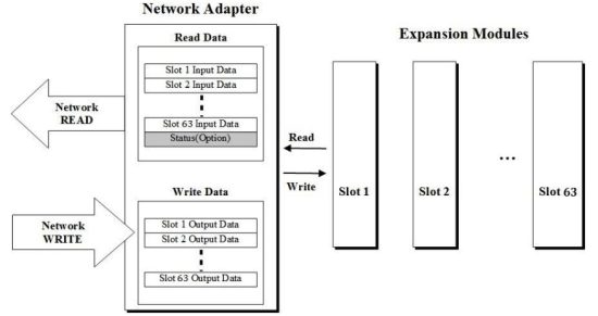 Data flow between network adapter (63 slots) and expansion modules
The input and output image data depend on the slot position and the data type of the expansion slot. The ordering of input and output process image data is based on the expansion slot position.
Calculations for this arrangement are included in the manuals for network adapter and programmable IO modules.
Valid parameter data depends on the modules in use. For example, analog modules have settings of either 0-20 mA or 4-20 mA, and temperature modules have settings such as PT100, PT200, and PT500. The documentation for each module provides a description of the parameter data.
Specifications
| Operating temperature | -20°C – 60°C |
| UL temperature | -20°C – 60°C |
| Storage temperature | -40°C – 85°C |
| Relative humidity | 5% – 90% non-condensing |
| Mounting | DIN rail |
| Shock operating | IEC 60068-2-27 (15G) |
| Vibration resistance | IEC 60068-2-6 (4 g) |
| Industrial emissions | EN 61000-6-4: 2019 |
| Industrial immunity | EN 61000-6-2: 2019 |
| Installation position | Vertical and horizontal |
| Product certifications | CE, FCC, UL, cUL |
4.2. General Specifications
| Power dissipation | Max. 35 mA @ 5 VDC |
| Isolation | I/O to logic: Photocoupler isolation |
| Field power | Supply voltage: 24 VDC nominal Voltage range: 15 – 28.8 VDC Power dissipation: 0 mA @ 24 VDC |
| Wiring | I/O cable max. 0.75mm2 (AWG 18) |
| Weight | 63 g |
| Module size | 12 mm x 109 mm x 70 mm |
4.2.1. Dimensions
 Module dimensions (mm)
4.3. Input Specifications
| Inputs per module | 8 points sink type |
| Indicators | 8 green input status |
| On-state voltage | 24 VDC nominal 15 – 28.8 VDC |
| On-state current | 2.2 mA @ 24 VDC 2.7 mA @ 28.8 VDC |
| Off-state voltage | 12.5 VDC @ 25 ℃ |
| Input signal delay | OFF to ON: Max. 0.3 ms ON to OFF: Max. 0.3 ms |
| Input filter | Adjustable, up to 10 ms |
| Nominal input impedance | 11.7K Ω typical |
| Common type | 8 points / 5 COM (sink) |
Wiring Diagram

| Pin no. | Signal description |
| 0 | Common (field power 24 V) |
| 1 | Input channel 0 |
| 2 | Input channel 1 |
| 3 | Common (field power 0 V) |
| 4 | Common (field power 24 V) |
| 5 | Input channel 2 |
| 6 | Input channel 3 |
| 7 | Common (field power 0 V) |
| 8 | Common (field power 24 V) |
| 9 | Input channel 4 |
| 10 | Input channel 5 |
| 11 | Common (field power 0 V) |
| 12 | Common (field power 24 V) |
| 13 | Input channel 6 |
| 14 | Input channel 7 |
| 15 | Common (field power 0 V) |
| 16 | Common (field power 0 V) |
| 17 | Common (field power 24 V) |
LED Indicator

| LED no. | LED function / description | LED color |
| 0 | INPUT channel 0 | Green |
| 1 | INPUT channel 1 | Green |
| 2 | INPUT channel 2 | Green |
| 3 | INPUT channel 3 | Green |
| 4 | INPUT channel 4 | Green |
| 5 | INPUT channel 5 | Green |
| 6 | INPUT channel 6 | Green |
| 7 | INPUT channel 7 | Green |
6.1. LED Channel Status
| Status | LED | Indication |
| No signal | Off | Normal operation |
| On signal | Green | Normal operation |
Mapping Data Into the Image Table
Input module data
| D7 | D6 | D5 | D4 | D3 | D2 | D1 | D0 |
![]() Input image value
Input image value
| Bit no. | Bit 7 | Bit 6 | Bit 5 | Bit 4 | Bit 3 | Bit 2 | Bit 1 | Bit 0 |
| Byte 0 | D7 | D6 | D5 | D4 | D3 | D2 | D1 | D0 |
Parameter Data
Valid parameter length: 2 bytes
| Bit no. | Bit 7 | Bit 6 | Bit 5 | Bit 4 | Bit 3 | Bit 2 | Bit 1 | Bit 0 |
| Byte 0 | Input filter value: 0 – 10 (unit: ms) | |||||||
| Byte 1 | Reserved | |||||||
Hardware Setup
CAUTION
- Always read this chapter before installing the module!
- Hot surface! The surface of the housing can become hot during operation. If the device is used in high ambient temperatures, always let the device cool down before touching it.
- Working on energized devices can damage the equipment! Always turn off the power supply before working on the device.
9.1. Space Requirements
The following drawings show the space requirements when installing the G-series modules. The spacing creates space for ventilation, and prevents conducted electromagnetic interference from influencing the operation. Installation position is valid vertical and horizontal. The drawings are illustrative and may be out of proportion.
CAUTION
NOT following the space requirements may result in damaging the product. 9.2. Mount Module to DIN Rail
The following chapters describe how to mount the module to the DIN rail.
![]() CAUTION
CAUTION
The module must be fixed to the DIN rail with the locking levers.
9.2.1. Mount GL-9XXX or GT-XXXX Module
The following instructions apply to these module types:
- GL-9XXX
- GT-1XXX
- GT-2XXX
- GT-3XXX
- GT-4XXX
- GT-5XXX
- GT-7XXX
GN-9XXX modules have three locking levers, one at the bottom and two on the side. For mounting instructions, refer to Mount GN-9XXX Module. 9.2.2. Mount GN-9XXX Module
To mount or dismount a network adapter or programmable IO module with the product name GN-9XXX, for example GN-9251 or GN-9371, see the following instructions: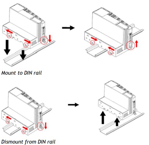 9.3. Mount Removable Terminal Block
To mount or dismount a removable terminal block (RTB), see the instructions below.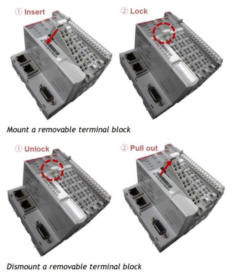 9.4. Connect Cables to Removable Terminal Block
To connect/disconnect cables to/from the removable terminal block (RTB), see the instructions below.
WARNING
Always use the recommended supply voltage and frequency to prevent damage to the equipment and ensure optimal performance.
9.5. Field Power and Data Pins
Communication between the G-series network adapter and the expansion module, as well as system / field power supply of the bus modules is carried out via the internal bus. It is comprised of 2 Field Power Pins and 6 Data Pins.
![]() WARNING
WARNING
Do not touch the data and field power pins! Touching can result in soiling and damage by ESD noise.
| Pin no. | Name | Description |
| P1 | System VCC | System supply voltage (5 VDC) |
| P2 | System GND | System ground |
| P3 | Token output | Token output port of processor module |
| P4 | Serial output | Transmitter output port of processor module |
| P5 | Serial input | Receiver input port of processor module |
| P6 | Reserved | Reserved for bypass token |
| P7 | Field GND | Field ground |
| P8 | Field VCC | Field supply voltage (24 VDC) |
Head Office
Beijer Electronics AB
Box 426
201 24 Malmö, Sweden
www.beijerelectronics.com / +46 40 358600
Documents / Resources
 |
Beijer Electronics GT-1358 Digital Input Module [pdf] User Manual GT-1358, GT-1358 Digital Input Module, GT-1358, Digital Input Module, Input Module, Module |