![]() AW-CU484 IEEE 802.15.4 and Bluetooth LE 5.0 Wireless
AW-CU484 IEEE 802.15.4 and Bluetooth LE 5.0 Wireless
Microcontroller Stamp LGA Module
User Guide
Revision History
| Version | Revision Date | Description | Initials | Approved |
| A | 2020/11/23 | • Initial Version | Shihhua Huang | N.C. Chen |
System Setup
Hardware Requirements
- Host system needs to run the Windows10 x64 operating system
- pixel-M8
- RF isolation chamber for receiving measurements.
- RF attenuators
- RF cable
- NFC reader
Software Requirements
- PL-2303GC Driver

- Tera Term (tool)
Note: Tera Term is our suggestion, you can try any terminal tool.

- DK6Production flash programmer folder (please contact FAE)
Note: You must have the below files

- Mbt.exe (please contact FAE)
Note: MBT is our suggestion. You can try any hci tool.

How to download the image
- You must check the COM number (can check the value by the following picture)
Note: J9 for DUT COM port

- Find the folder of DK6ProductionFlashProgrammer, and type cmd to get into the Dos window.

- Key in
• ZIGBEE IMAGE:
DK6Programmer.exe -s com6 -p JN-AN-1242-JN518x-Customer-Module-Evaluation-Tool.bin
• BLE IMAGE:
DK6Programmer.exe -s com6 –p qn9090dk6_hci_black_box_bm.bin
*You must note the step. If you key in the format before getting into download mode (DK6Programmer.exe -s com6 -p JN-AN-1242-JN518x-Customer-Module- Evaluation-Tool.bin), you need to keep holding the ISP button and Reset button, and then release the ISP button after releasing the reset button.
To open the tool and download the image file (com6 is your DUT J9 COM port)

- Select Y

- Finish

Test mode(In Zigbee)
- Open the Tera Term
- Select setup →Serial port
• Setting COM port (J9 com port)
• Baud rate is 115200 - Select setup →Terminal
• Receive – select LF
• Transmit – select CR+LF

- Select a) standard module

- Select a) Regular

- Customer Module Evaluation Tool (main menu)
• Select “g” trigger packet test (Rx test)
• Select “I” transmit packet test (Tx test)

- RX test (Select g)
• g → Start test (start to receive the package)
• +/- → Increment or decrement channel
• X → Return to the main menu
• /→Reset
- TX test (Select i)
• +/- → Can control the channel
• F → Fast transmit rate (fast transmit can help modulation to catch signal)
• X → Return to the main menu
• /→Reset
- NTAG tests(Select n)
Select Internal or External NTAG
• Select a) internal NTAG
NTAG Tests (Internal)
• Select a) read contents of EEPROM
• Select b) write data to EEPROM

- Read contents of EEPROM
Can read the NFC MAC in Block 0: 04830C3AE26180

- Write data to EEPROM
Use this test to write data to EEPROM, Format is:
1:0 1 2 3 4 5 6 7 8 9 A B C D E F
Programs 0 to F in block 1

Test mode(In BLE)
- Open the folder of MBT

- Open the mbt_setup.ini
Setting MBT_TRANSPORT=COM3 (your DUT COM port J9)
DOWNLOAD_BAUDRATE=115200
APPLICATION_ BAUDRATE=115200
Enable_Debug_Message=1
DOWNLOAD_DELAY = 50
[Solution] Type=2

- And type cmd to get into the Dos window.

- Key in mbt.exe

- Main menu
If you need more information, please key in mbt help.

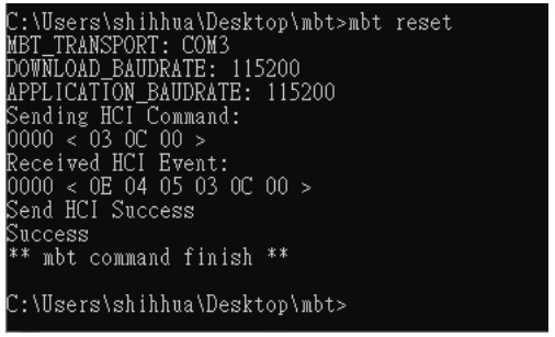
- Key in MBT reset
Make sure the DUT has been reset.
FCC Statement
This equipment has been tested and found to comply with the limits for a Class B digital device, pursuant to Part 15 of the FCC Rules. These limits are designed to provide reasonable protection against harmful interference in a residential installation. This equipment generates, uses and can radiate radio frequency energy and, if not installed and used in accordance with the instructions, may cause harmful interference to radio communications. However, there is no guarantee that interference will not occur in a particular installation. If this equipment does cause harmful interference to radio or television reception, which can be determined by turning the equipment off and on, the user is encouraged to try to correct the interference by one of the following measures:
- Reorient or relocate the receiving antenna.
- Increase the separation between the equipment and receiver.
- Connect the equipment into an outlet on a circuit different from that to which the receiver is connected.
- Consult the dealer or an experienced radio/TV technician for help.
This device complies with Part 15 of the FCC Rules. Operation is subject to the following two conditions: (1) This device may not cause harmful interference, and (2) this device must accept any interference received, including interference that may cause undesired operation.
IMPORTANT NOTE:
This module is intended for OEM integrators. This module is only FCC authorized for the specific rule parts listed on the grant, and the host product manufacturer is responsible for compliance to any other FCC rules that apply to the host not covered by the modular transmitter grant of certification. The final host product still requires Part 15 Subpart B compliance testing with the modular transmitter installed.
Additional testing and certification may be necessary when multiple modules are used.
20cm minimum distance has to be able to be maintained between the antenna and the users for the host this module is integrated into. Under such configuration, the FCC radiation exposure limits set forth for an population/uncontrolled environment can be satisfied.
Any changes or modifications not expressly approved by the manufacturer could void the user’s authority to operate this equipment.
USERS MANUAL OF THE END PRODUCT:
In the user’s manual of the end product, the end-user has to be informed to keep at least 20cm separation with the antenna while this end product is installed and operated. The end-user has to be informed that the FCC radiofrequency exposure guidelines for an uncontrolled environment can be satisfied.
The end-user has to also be informed that any changes or modifications not expressly approved by the manufacturer could void the user’s authority to operate this equipment.
This device complies with Part 15 of FCC rules. Operation is subject to the following two conditions: (1) this device may not cause harmful interference and (2) this device must accept any interference received, including interference that may cause undesired operation.
LABEL OF THE END PRODUCT:
The final end product must be labeled in a visible area with the following ” Contains TX FCC ID: TLZ-CU484 “.
This device complies with Part 15 of FCC rules. Operation is subject to the following two conditions: (1) this device may not cause harmful interference and (2) this device must accept any interference received, including interference that may cause undesired operation.
Antenna Information
| Ant. | Brand | Model Name | Antenna Type | Gain (dBi) |
| 1 | LYNwave | ALX20M-052AA1 | PI FA Antenna | 3. |
This device contains license-exempt transmitter(s)/receiver(s) that comply with Innovation, Science, and Economic
Development Canada’s license-exempt RSS(s). Operation is subject to the following two conditions:
- This device may not cause interference.
- This device must accept any interference, including interference that may cause undesired operation of the device.
IC Radiation Exposure Statement:
This equipment complies with IC RSS-102 radiation exposure limits set forth for an uncontrolled environment. This equipment should be installed and operated with a minimum distance of 20cm between the radiator & your body.
IMPORTANT NOTE:
This module is intended for OEM integrators. The OEM integrator is responsible for compliance with all the rules that apply to the product into which this certified RF module is integrated.
Additional testing and certification may be necessary when multiple modules are used.
Any changes or modifications not expressly approved by the manufacturer could void the user’s authority to operate this equipment.
USERS MANUAL OF THE END PRODUCT:
In the user’s manual of the end product, the end-user has to be informed to keep at least 20cm separation with the antenna while this end product is installed and operated. The end-user has to be informed that the IC radio-frequency exposure guidelines for an uncontrolled environment can be satisfied.
The end-user has to also be informed that any changes or modifications not expressly approved by the manufacturer could void the user’s authority to operate this equipment. Operation is subject to the following two conditions: (1) this device may not cause harmful interference (2) this device must accept any interference received, including interference that may cause undesired operation.
LABEL OF THE END PRODUCT:
The final end product must be labeled in a visible area with the following ” Contains IC: 6100A-CU484 “.
The Host Model Number (HMN) must be indicated at any location on the exterior of the end product or product packaging or product literature which shall be available with the end product or online.
Documents / Resources
 |
Azurewave Technologies AW-CU484 IEEE 802.15.4 and Bluetooth LE 5.0 Wireless Microcontroller Stamp LGA Module [pdf] User Guide CU484, TLZ-CU484, TLZCU484, AW-CU484 IEEE 802.15.4 and Bluetooth LE 5.0 Wireless Microcontroller Stamp LGA Module, IEEE 802.15.4 and Bluetooth LE 5.0 Wireless Microcontroller Stamp LGA Module |


