![]()
![]()
USER MANUAL

Version 2.3.1
Introduction
Features at a Glance
eDRUMin devices are e-drum to MIDI interfaces with universal trigger inputs supporting pad, cymbals, and acoustic triggers. Flexible trigger circuity that allows them to support both piezo / piezo pads and piezo / switch pads. 10 bit sampling at up to 10K samples /per second / input ensures high resolution triggering with extremely low internal latency and jitter.
| Supports Roland and Yamaha 3-way triggering | |
| Hotspot suppression for mesh pads. | |
| Positional Sensing for cymbals and mesh pads with center mounted piezo. | |
| Bezier Velocity Curves | |
| Ultra compact and portable design | |
| Roland Bell Sense for 3-Way triggering using a single input | |
| Full Size MIDI ports for interfacing 3rd party gear * | |
| Hihat input supporting Yamaha and Roland style controllers | |
| USB Host port for expansion ** | |
| Powerful and intelligent UI for easy setup |
* eDRUMin 4 and eDRUMin 8 only have a MIDI Out port while the eDRUMin 10 has both MIDI In and Out.
** USB Host port is NOT available on the eDRUMin 4.
The Hardware and Connections
 Pedal Input
![]() The pedal input on the back of the eDRUMin does not support drum pads. The Jack uses DC current which can damage the drum pads. Look on the next page for more information about the type of pedals you can connect.
The pedal input on the back of the eDRUMin does not support drum pads. The Jack uses DC current which can damage the drum pads. Look on the next page for more information about the type of pedals you can connect.
DC Power Connector
eDRUMin devices typically use power from the USB cable. If you want to use your eDRUMin in standalone mode, you can power it with a USB charger or the DC Power Jack.
eDRUMin devices use a BOSS style jack, where the center pin is negative.
The eDRUMin 4 needs at least 100mA, and the eDRUMin 10 needs at least 200mA, or 600mA if also using the USB host port. The BOSS PSA-120S is great choice for either device. Note the ED8 does not have a DC adapter.
![]()
Supported Pads
eDRUMin supports all kinds of e-drum pads and triggers. It doesn’t matter if your pads are made by Roland, Yamaha, Alesis or anyone else; they are well supported. Here’s a list of the gear used during development.
| Electric Drum Pads Roland PDX-125k Roland PDA-120LS Roland PD-8 Roland KD-8 Roland KT-10 Roland HD-1 Toms Roland BT-1 Yamaha TP-65s Yamaha TP-120SD DDT MS-140C ATV AD-S13 |
Electric Cymbals Roland CY-12C Roland CY-13R Roland CY-15R Roland CY-8 Roland VH-10 Hihat Roland VH-13 Hihat Yamaha PCY155 Lemon 18” Ride |
Acoustic Triggers Roland RT-30HR |
Note: Center mounted mesh tigger systems that use cylinders instead of cones (Jobeky for example) tend to produce signals that are too hot for the eDRUMin inputs. Visit the eDRUMin forums for more information.
Supported Hihat Controllers
The hihat controller input on the back of the device supports both Roland and Yamaha style hihat controllers, expression pedals, sustain pedals, and footswitches. Look in the Appendix for wiring diagrams for supported pedal types.
Note: When setup as an expression pedal, the pedal input can supply 3.3V to power most 3.3V compatible Hall effect sensors.
Typically this input is used for a hihat controller, but it can also be used to Change Banks of notes, send Control Change messages and more.
Pedal Sensing automatically sets up your pedal. Always connect the cable to your pedal before connecting to the eDRUMin. Look here to see what the various types of pedals can do. Here’s a list of the pedals I used during development.
| Hithat Controllers Yamaha HH65 Roland FD-8 Roland VH-11 Roland VH-13 |
Expression Pedals Moog EP-3 Roland EV-5 Yamaha FC7 M-Audio EX-P Behringer FCV100 Line6 EX 1 |
Sustain Pedals Yamaha FC3A Yamaha FC4 Yamaha FC5A Roland DP-10 |
Footswitches Yamaha FC5 Boss FS-7 Marshall 90010 |
Getting Started
Attaching the Drum Stand Clip
You can use the optional drum stand clip to attach your eDRUMin to the frame of a drum stand or a hihat stand.
Below are instruction for attaching the clip of the eDRUMin 4, but the process is the same for the eDRUMin 10. Make sure your clip is very tight to ensure there’s enough friction to prevent slipping.
- Insert the strap through the slot to make a loop.

- Place the eDRUMin inside the loop. With the device centered on the clip, pull the strap tight.

- Place the device and the clip against the frame of your drum stand. Wrap the strap around the frame and insert it through the slot.

- Pull the strap very tight and wrap back around the device. Stick the Velcro to secure it in place.

Because eDRUMin devices are class compliant, there’s no need to install drivers. You will however want to install the Control Application to edit the device settings.
Installing the Control Application
The Control application is available for Windows, macOS, Linux, and iOS and can be downloaded from the Audiofront downloads.
The Control Application is discussed in detail in the next section of the manual.
Enabling eDRUMin in your MIDI Applications
When you use your eDRUMin for the first time with a new application, you might need to enabled it for input in the application’s audio / MIDI setup. Here are some screenshots showing how to enable eDRUMin in various applications.

Connecting Drum Pads
The 1/4” inputs on the front of the device are for connecting drum pads. Make sure you connect your pads with TRS connectors. The device is not designed to work with TS connectors. Even if you are using a single zone pad, you should still connect it with a TRS cable.
 Some ride cymbals have two TRS connectors. If you plan two use both connections for 3way triggering, connect them to two adjacent inputs as shown in the image below. Next, set the pad type of the BOW / EGDE input to ‘Roland 3-Zone Ride’ and the second input will automatically be marked as ‘Bell’

Loading a Pad Preset
You can load presets for your pads by clicking on the Preset Manager Icon.![]()

If a preset for your pad is not available, you’ll need to set it up manually by setting the pad type and adjusting its trigger settings.
Look here for more information about use the Preset Manager.
Drum Maps and Kit Pieces
eDRUMin uses the idea of drum maps and kit pieces. The device contains a drum map and inputs are assigned to kit pieces. The device determines which notes a particular input should trigger by looking them up from the drum map.
This system allows the user to trigger different hardware / software by simply changing drum maps.
Click on Kit Piece selector, shown right, to reveal and select a kit piece.

Changing Drums Maps
eDRUMin comes with several factory drum maps. You can access them by clicking on the drum map indicator.
 Double click a factory drum map to send it to your device.

Users can create their own drum maps and edit them for their own needs.
Look here for more information about the Drum Map Editor.
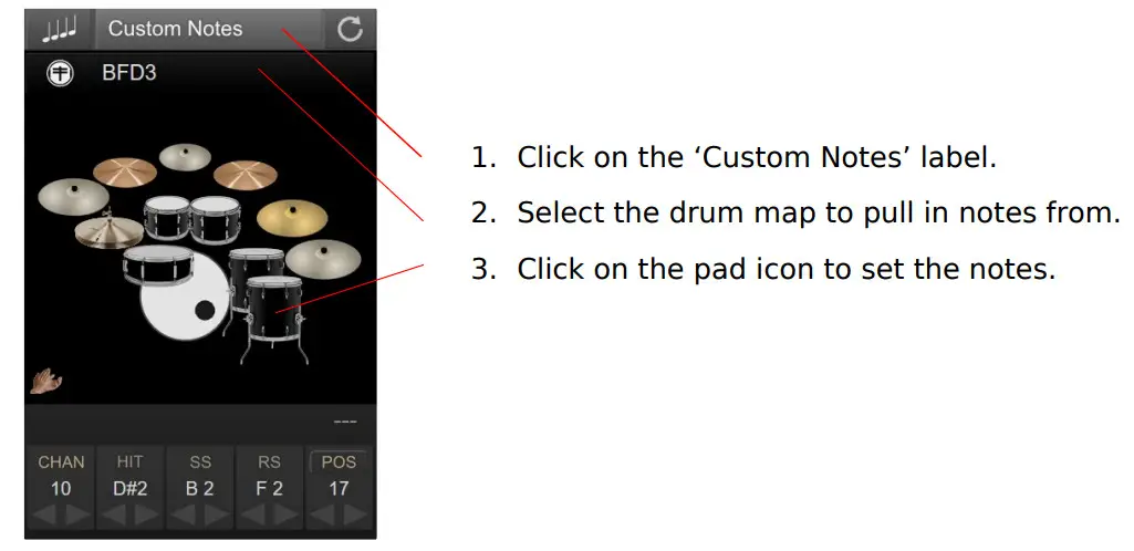
Custom Note Assignments
If you do not want to use predefined note assignments from a drum map, you can set your pad to use Custom Notes.
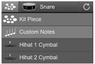 When you switch to ‘Custom Notes’, you can change note assignments by dragging up and down, using the arrows, or double clicking and entering either a note or note number.
Setting up a Hihat Controller
Like connecting pads, make sure you connect your hihat controller using a TRS cable.
Connect the cable to your hihat controller before plugging it into one of the pedal inputs on the back of the unit.
eDRUMin will attempt to auto detect your hihat set it up automatically. If your pedal isn’t working properly after you connect it, you can set it up manually or load a pedal preset if one is available.
Loading a Pedal Preset
To load a pedal preset, click on the Preset Manager icon.![]()
 After the Preset Manager opens, click on the pedal input. It will turn green and the Preset Manager will list all the factory hihat controller presets.

On the left is a list of the factory hihat presets. If your hihat controller is not listed, you need to set it up manually.
Typically all that you need to do is calibrate its range.
Look here for information about setting up your hihat controller.
Setting up your hihat Cymbal
To function optimally, especially if using Hihat Levels mode, the input you use for your hihat cymbal needs to be set to ‘Hihat Cymbal’.
If you are using an eDRUMin 10, you will see ‘Hihat 1 Cymbal’ and ‘Hihat 2 Cymbal’ because it has two pedal inputs.

The Control Application
As your eDRUMin has no buttons or controls, you’ll need to use the software control application to edit settings on the device.
The Control Application doesn’t need to be running for the device to work. All the processing and settings are saved on the device itself. By default, any changes you make with the Control Application are saved automatically 5 seconds after the last edit.
Make sure you wait a few moments after making a change before unplugging the device.
The Control Application can be resized as you see fit. Just grab one of the corners and drag it to the size you want. The size and position are saved and restored the next time you open the application. Also, you can easily move the application around by clicking and dragging on any empty space in the background of the application or controls.
The Input Selector
The topmost part of the eDRUMin control application is reserved for selecting the device and input you want to edit.
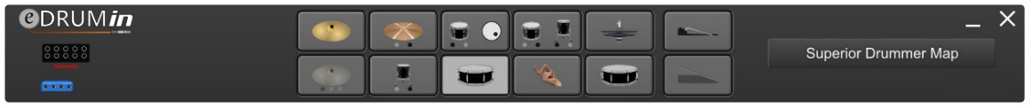
An input can be selected for editing by clicking on its graphic. Assuming the Auto-Select control is on, you can simply hit a pad and it will be automatically selected and ready for editing.
If you have more than one device connected, icons for each device become visible on the right hand side, allowing you to select which device you want to edit. The top row of device icons are for devices that are connected by difference USB ports. Devices plugged in the USB host port of an eDRUMin 10 appear on the bottom row.
Sidebar
The Sidebar gives quick access to pages of controls as well as a few useful settings.

Trigger Editor
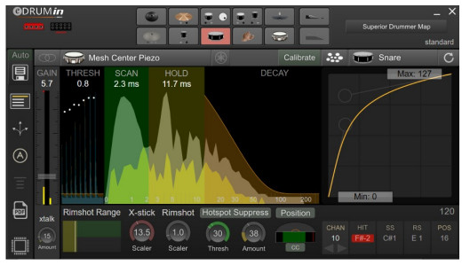
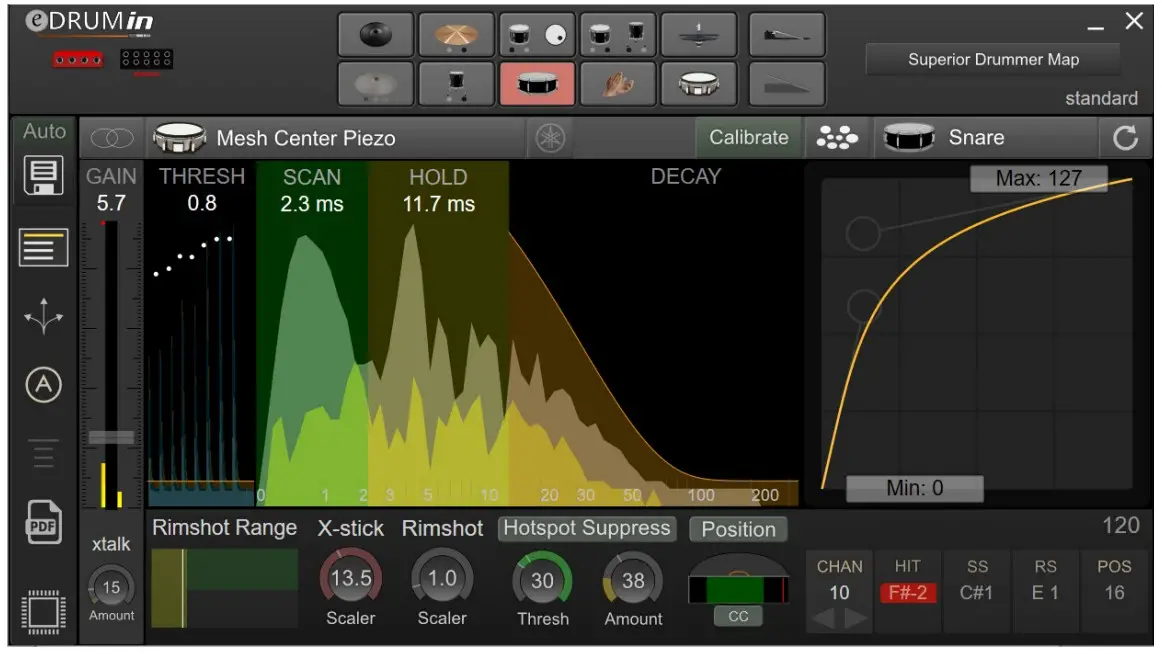
The Trigger Editor is divided into functional groups for configuring the type of pad, adjusting basic scan settings, processing sense data, and controlling the MIDI output.
The sections are outlined in the image below.

Pad / Input Type Settings
Whenever you connect a new pad to the device, these are the settings you should adjust first.

Input Mode
Each input can function as a stereo input (for dual / triple zone pads), mono (single zone pads), and dual mono (two single zone pads connected to a single TRS cable).
Pad Type Selector
The pad type selector determines how the input will be wired electronically, and which controls are available to edit.
When you press the Pad Type Selector, the following panel appears and you can select the type that best matches your pad.

Because of the diversity of metal cymbal configurations, an extra setting is needed. 3-Zone metal cymbals support a bell that uses a piezo or a switch, and dual zone metal cymbals support Piezo / Switch or Piezo / Piezo configurations.

Note: If an input is set to a piezo / switch pad, but you connect a piezo / piezo pad, the wiring of the input can put strain on the ring piezo. To protect your pads, eDRUMin will test inputs and indicate a compatibility issue(!) if there’s a problem.
It’s recommended to always unplug the TRS cable from the eDRUMin when changing pads.
Take a look in the appendix for wiring diagrams.
![]() Yamaha Wiring Toggle
Yamaha Wiring Toggle
eDRUMin devices support both Roland and Yamaha style wiring. Some of the Sensing Controls need to know how the pad is wired in order to work properly. If, for example, the Hotspot Suppression is not working well for you, it could be that you need to toggle
this switch. Look at the Wiring Diagrams in the appendix for more information about how pads should be wired.
![]() Activate Calibrate Mode
Activate Calibrate Mode
Calibrate mode allows you to set basic scan settings for your pad by simply hitting it with your drum sticks. Look on the following page for more information.
Calibrate Mode
Calibrate Mode is designed to allow you to quickly setup a pad without needing to fiddle around with controls. You simply turn on Calibrate Mode, hit your pad to calibrate it, and turn it off again when you are done.
Before turning on Calibrate mode, make sure that you have already selected the appropriate pad type.

When you first activate Calibrate Mode, the GAIN, THRESH, SCAN, HOLD, and the SCALER controls will be highlighted in green. As you hit the different parts of your pad, the controls are adjusted automatically to provide enough headroom. The harder you hit, the more headroom is provided. You can override the automatic calibration of any control by moving it with your mouse. The control will lose its green highlighting and will no longer be automatically adjusted.
When you are happy with the results, turn Calibrate Mode off to save the settings.
Calibrating a Dual Piezo Pad / Trigger
Start by hitting the pad off-center to calibrate the gain control. Avoid hitting directly over the sensor of the pad, as this can drag down the gain control too quickly.
Next, hit the head of the pad near the edge. This will help get a good calibration for the HOLD control.
Lastly, hit the rim of the pad to calibrate the X-stick SCALER.
Calibrating Cymbals
Begin my hitting the bow to calibrate the gain of the pad. Next hit the edge and the bell to calibrate the SCALERS.
Transient Scanning Controls
eDRUMin provides a very clear graphical representation of the transients from your pads which makes adjusting controls intuitive and easy.
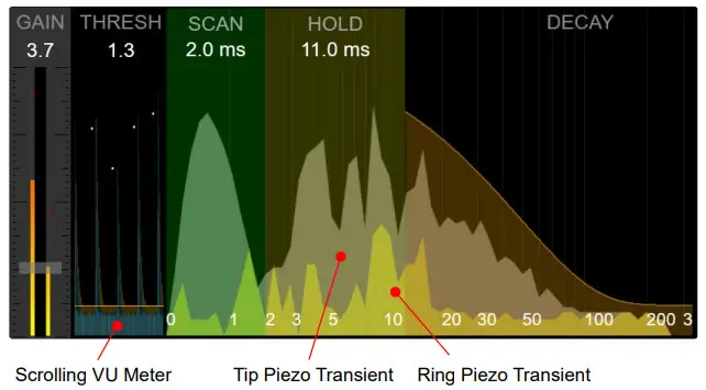
The amplitudes and time scales in the graphics are not linear. The amplitudes are exponentially scaled so that more detail and resolution is available for low amplitudes, making it easier to properly set the Thresh control. Similarly, the time scale is also scaled exponentially to give more detail and resolution at the very start of the transient, making it easier to accurately set the Scan control.
Gain
The gain control acts as a master gain for the input. Adjusting it affects the velocities of all articulations. To adjust the velocities of individual articulations, take a look at the Articulation Scalers.

Thresh
This is the minimum amplitude required to start scanning a transient. Make sure you set it a bit above the noise floor or you will get false triggers, especially when the Control Application is running.
Scan
Dragging anywhere on the green scan area will allow you to change the SCAN time. You want to keep the SCAN time as short as possible, while ensuring that it covers the major peeks at the beginning of a transient. Scan time adds to the overall latency of the generated MIDI notes, so a compromise between velocity accuracy and note latency has to be made.
Note: The Hotspot Suppression and Positional Sensing features need at least 2.3 ms of scan time to function properly. If the scan time is less than 2.3 ms, they will be disabled.
Hold
Often a high peek arrives late in a transient. In the graphic above, you’ll see that the highest peek actually comes at about 9 ms. Any late peaks need to be covered by the HOLD control of they will cause a second hit to be registered. Keep in mind that long hold times limit the device’s ability to trigger accurately during drum rolls and buzz rolls, so don’t set it any longer than it needs to be.
Decay
The last of the transient scan controls is the DECAY control. You need to adjust it to loosely follow the natural decay of your transients. If you are too aggressive (try to follow the natural decay too closely), you could end up with double hits. At the same time, if you leave this control too relaxed, the device’s ability to track fast drum rolls will be compromised.
Crosstalk Cancellation
![]() Sometimes vibrations from hitting one pad can travel though a drum stand and into an adjacent pad, registering a hit even though it hasn’t actually been hit. This is called crosstalk. The CROSSTALK control is designed to prevent those vibrations from triggering notes.
Sometimes vibrations from hitting one pad can travel though a drum stand and into an adjacent pad, registering a hit even though it hasn’t actually been hit. This is called crosstalk. The CROSSTALK control is designed to prevent those vibrations from triggering notes.

 To better see the effect of this control, turn Auto Select off, and watch in the Scrolling View as you hit adjacent pads. The amount of crosstalk cancellation is shown in red. Adjust the CROSSTALK control until the red covers the blue vibrations.
MIDI coming into the device from the USB port is also used in the calculation of crosstalk.
If for example you are using 2 eDRUMin devices, you can use a DAW environment to route the output of one device into the other and vice versa. This will help prevent crosstalk between the two devices.
eDRUMin 10 devices also apply crosstalk cancellation to MIDI coming in from device connected to the USB host port and MIDI in DIN. Look here for more information about the flow of MIDI between connected devices.
Articulation Scalers
 Depending on your input settings (input mode and pad type), one or two articulation scalers will be visible.
For a stereo dual zone pad, the scaler controls are called X-stick and Rimshot. For a 3 zone cymbal (using two inputs or Bell Sense), they are called Edge and Bell.
The velocities for various articulations are calculated based on the GAIN control multiplied by the respective scaler. These settings are automatically calculated when you calibrate you pad using Calibrate Mode.
Metal Cymbal Thresh Controls
 For metal cymbal pad types, thresh controls are shown next to the articulation scalers. The thresh controls allow you adjust the sensitivity of zones to prevent false triggering. As you hit your cymbal on a particular zone, the indicator on the thresh control will move. If it falls within green area of the meter, the particular zone be activated. Increase the value of the control to make the zone more difficult to trigger.
Sense Controls
The sense controls that are available depend the Input Mode and Pad Type settings.
Most of the Sense Control are more advanced controls and you should make sure you have your pad triggering well before adjusting these controls.
Rimshot Range
The Rimshot Range control allows you to fine tune rimshot detection on dual piezo pads. It consists of an indicator and three sections. The yellow section represents a head hit, the green section represents a rimshot, and the dark grey is for sidestick.

When you hit the head of your pad, the indicator will move to the left, and when you hit the rim, the indicator will move towards the right. The section that lies under the top tip of the indicator determines which articulation is triggered. In the image above, a rimshot is triggered. Watch the position indicator and adjust the size of the sections.
Hotspot Suppression
One of the annoying qualities of a mesh pad with a center mounted piezo is a sensitive region of the drum head directly over the piezo. The Hotspot Suppression control detects impacts over the piezo and suppresses their amplitudes, evening out the response of the entire playing surface.
The hotspot suppression needs about 2.3 – 3 ms of data to work properly. If you have the SCAN control set below 2.3 ms, the control will become disabled.
There are 3 separate controls, ‘Thresh’, ‘Amount’, and ‘Scaler’ which is a small knob on the inside of the ‘Thresh’ control.
Start by adjusting the ‘Amount’ and ‘Scaler’ controls to zero.
Next, watch the meter of the ‘Thresh’ control as you hit different parts of the drum head. As you hit the pad around the hotspot, you should see the meter values increase. Set the ‘Thresh’ control so that hits away from the hotspot register in the dark part of the meter, and hits over the hotspot register in the green part of the meter.

If you find that it difficult to get good separation between the hotspot and area further off center, you can try increasing the ‘Scaler’ control. This give you better separation, but reduces the ability to suppress low velocity hits on the hotpot.
After you have properly set the ‘Thresh’, adjust the ‘Amount’ control to reduce the amplitude of the hits that register in the green part of the meter.
Note: Hotspot suppression is designed to work with Roland style pad construction. It works by analyzing the waveform coming from a pad. If the incoming signal coming from your pad is not clean and free of noise, this feature will not work. This is a particular concern for A→E conversions and DIY pad construction. Visit the eDRUMin troubleshooting forum for more information.
Note: When you change drum sticks, you might need to adjust the THRESH control. Generally speaking, heavier sticks will need a slightly lower THRESH, and lighter sticks will need a higher THRESH.
Edge Sense
When the Input Mode is set to ‘Mono’ or ‘Dual Input’, Edge Sense becomes visible. This control is designed to detect a second articulation for a pad that uses a single piezo. By activating this control, a second ‘Note’ will appear in the Note Panel.
 This feature will not work with all pads. When you hit the edge of your pad, check the meter in the Thresh Control. Does it increase? If it does, adjust the Thresh control so that hits on the center of the pad register below the thresh, and hits to the edge of the pad register inside the green meter.
Bell Sense
Bell Sense is a feature that’s designed to provide reliable and dynamic bell triggering for cymbal type pads using only only a single input.
Supported Cymbals
Currently there are custom Bell Sense algorithms to support the Roland CY-12, CY-13R, CY-15R and CY-8 cymbals. More cymbals can and will be added in the future. If you have a popular cymbal that’s not currently supported, contact technical support as it might be possible to add support for it.
NOTE: If you have an unsupported cymbal that uses a second input for bell triggering, you can still get 3way triggering from your pad using the “Roland 3-Zone Ride” pad type, but you will need to use two inputs on the eDRUMin. In this configuration, the second input acts as a ‘Bell’ input and the triggering will behave much like it does on a Roland module.
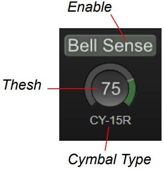
Adjusting the Controls
To enable Bell Sense, click on the ‘Bell Sense’ label. When the control is enabled, the ‘BELL’ articulation becomes visible in the Note Panel.
Next, click on the Cymbal Type control to scroll to select the setting that best makes your cymbal.
The Thresh control can be used to fine tune the cutoff between Bow and Bell articulations. When you hit the cymbal, it registers on the meter. Only hits that register in the green part of the meter will trigger the bell articulation.
For best results, you should leave the THRESH set at 75.
Positional Sensing
eDRUMin supports positional sensing for ‘Mesh Center Piezo’ or ‘Mesh 3 Side Sensors’ pads as well as compatible cymbals. The device can send out the position as a Control Change message (CC), or a separate Edge Note.
The CC or Note value is set in Note Panel.
The setup for ‘Mesh 3 Side Sensors’ pads is described on the next page.

Setup For Mesh Center Piezo Pads
To get positional sensing working, you’ll need to adjust the Range controls. In the picture on the right, the Range controls are represented by the green bar, and a red line represents the positional measurement.
The Min Range control defines the size of the ‘center’ region of the pad. When hitting directly in the center of the pad or even slightly off-center, the position indicator should fall to the far right, but as you hit closer to the edge, the red indicator will suddenly jump over towards the right. The Min Range control should be set somewhere between the far left and the point where the indicator just starts to jump to the right.
The Max Range control helps define the sizes of the off-center and edge portions of the pad. As you drag the control further left, the size of the off-center region increases and the size of the edge region decreases.
If using a stereo pad, an additional control is available by clicking on the ‘T’ to change it to ‘R’. ‘R’ is for ring, and this control uses information from the ring piezo to improve stability of off center hits. When the red indicator falls into the orange rectangle, the measured position is constrained to be at least 64.

Understanding the Positional values
When the pad is hit in the center, the eDRUMin sends a CC value of 0, at the point where the positional sensing begins to register, it sends a CC value between 64 and 127 depending on how close to the edge you hit.
If you are sending a Note instead of a CC, the eDRUMin will send the ‘edge’ note when the calculated CC value is greater than 95. You can adjust Range Max control to adjustthe transition point between ‘center’ and ‘edge’.
Setup For Cymbals
There are two different positional sensing algorithms for cymbals. The first one is designed to support Roland and ATV cymbals, and the second is a more generic approach that was designed to support the Lemon 18” Ride and may also work with some other cymbals.
You can switch between the two algorithms by pressing the button shown in the image on the right.
The rest of the controls work in a similar fashion as described above.

Setup For Mesh 3 Side Sensors Pads
Positional Sensing for pads with 3 side centers was modeled using an ATV S13 snare and a Roland PDA120LS and may not generalize with other pads. For best results, make sure you scan time is between 2.3 and 2.6 ms.
There are 3 filters to detect off-center and edge hits.
Each filter can be turned off by setting its value to zero.

A hit is first processed by the Off-Center control. If not ‘handed’ by the Off-Center control, the hit is sent to the Time Thresh Control.
Note: All hits are processed by the Edge Thresh and it trumps the other two controls.
Off-Center Size
The image on the right shows how this control works.
Roughly speaking, any hit in the yellow area will be ‘handled’ by this control.

And any hit that falls into the green area will detected as ‘offcenter’ and assigned a CC value between 64 and 127. Any other hit in the yellow are will be assigned a CC value of 0.
For low values, few hits will be detected as off-center, making the center area large. However, this also results some hits closer to the edge to be marked as center (unless caught by the Edge Control).
For high values, more hits towards the edge are marked as ‘off-center’, but the size of ‘center’ are is reduced, so there’s a trade off. For best results, you set this control as high as you can without making the center too small.
Note: The size of the yellow area is influenced by the input’s scan time setting. For good results, a minimum of 2.3ms is needed. Increasing the scan time up to 2.7ms may increase the size of the yellow area.
Time Thresh
Only hits not handled by the Off-Center control are processed by the Time Thresh control, so it’s often helpful to turn off the off-center control off when making adjustment.
The indicator of the Time thresh control shows the length of a hit. If the indicator falls inside the green part of the control, then the hit is deemed to be an offcenter hit and assigned a CC of 64.

By default the indicator must be greater than the threshold, but by clicking the ![]() button you can change it to less than.
button you can change it to less than.
Edge Thresh
If your pad is stereo (dual zone), information from the ring sensor can also be used to detect hits close to the edge of the pad. If a hit falls into the green area of the meter, the hit will be assigned a CC value of 127. The control adjusts the size of the green area.

Output Settings
These settings adjust the MIDI messages that the device will output for the selected input.

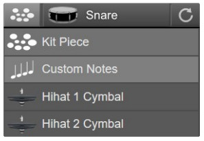
Pad Function
By default, inputs are set to ‘Kit Piece’, which means that they output MIDI notes based on the currently loaded drum map.
Look here for more more information on using drum maps.
For more control over the notes a pad outputs, change the pad function to ‘Custom Notes’.
This lets you change the notes without having to edit and load a custom drum map.
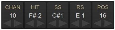
Depending on how an input is configured, you’ll see the MIDI Channel control and up to 4 different Note controls.
If the selected input is set to a ‘kit piece’, only the CHAN control can be changed, as the notes are defined by the drum map and the specified kit piece.

If the input is set to ‘Custom Notes’, then the notes can be adjusted by dragging with mouse, using the increment and decrement buttons, or by double clicking and entering a number or note.
Note: You can switch showing Notes or Note Numbers by right-clicking on a note control. This will change the setting for all note controls and the setting will be remembered the next time you open the Control Application.
Pull Notes from Drum Map
If your pad is set to ‘Custom Notes’, you can still pull notes in from a drum map.
Depending on the type of pad you are using and your trigger settings, the last note control will be called ‘POS’ for positional sensing, or ‘CHOKE’ for cymbal choking.
Note: If the pad function is set to ‘kit piece’, then the POS and CHOKE settings are handled by the drum map. If you would like the change those settings, you will need to set your pad function to use ‘Custom Notes’ or edit and load a new drum map.
POS
This is shown when positional sensing is enabled for the current pad. Positional Sensing on eDRUMin is communicated by either sending out a Continuous Control (CC) message corresponding to the position of the hit, or as a separate Edge note. corresponding to the position of the hit. Look here for more information about setting up positional sensing.
CHOKE
Choke is shown for dual zone cymbals that do not have positional sensing enabled.
While eDRUMin always sends aftertouch messages for cymbal choking, it also allows you to specify a MIDI Note for choking your cymbals in addition to sending aftertouch messages to support applications and hardware that do not support aftertouch messages.

To enabled sending a choke note, click on the ‘CHOKE’ label.
Note: If you are using positional sensing with a cymbal, then sending a choke note will not be available.
Choking with aftertouch, however, will function as normal.
Velocity Curves
Getting an electric drum pad to have the same dynamics as a real drum is a big challenge. Getting realistic drum rolls from a mesh drum pad, for example, can be tricky because the dynamics of mesh and a real drum head are quite different.

To overcome this challenge, eDRUMin devices implements cubic Bezier curves to remap the velocity curve of your hits. The Bezier handles let you draw all kinds of curves while ensuring a smooth transition from the lowest to the highest velocities.
In the image on the left, the curve is being used to make drum rolls on a mesh head feel like a proper drum. After you’ve gotten your pad triggering well, the Response Curve is the most powerful tool to get it sounding a natural as possible.
Note: By default, the articulations for a single pad all share the same velocity curve. To access independent velocity curves for each articulation, the device needs to be in Advance Mode (described on the following page)
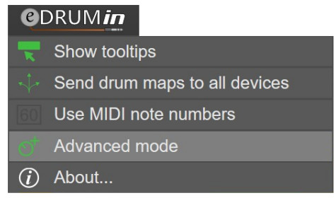
Advanced Mode
In an effort keep eDRUMin simple to use, some of the more advanced features of the device are hidden by default. You can enabled advanced mode by clicking on the eDRUMin logo and selecting the ‘Advanced mode’ option.
This setting is stored on the device, so each connected device can be in advance or standard mode. Advanced mode unlocks to the following features:
- Note Banks
- Independent velocity curves for each articulation.
- Control Change and Record assist functions for triggers.
- Impact Mode for triggering the closed hihat articulation.
Working With Note Banks
Each input has four banks where you can save different sets of channel and note assignments. If an input is setup a Kit Piece, then only the channel setting will be used and note assignments will still be drawn from the drum map.

The currently selected bank can be changed by:
- Clicking on the bank number
- Using an attached sustain or footswitch
- Sending Program Change messages
Hihat pedals also have four note banks. When the hihat pedal is linked to a trigger input, their selected note banks are also linked. Changing the selected note bank for the hihat cymbal will also change the selected note bank for the hihat pedal and vice-versa.
Working with Independent Curves
An independent curve can be setup for each articulation of a pad. By default, each articulation shares the same velocity curve as the first articulation. To enable an independent curve, select the articulation by clicking on its label. Next click on the ‘Independent’ button.
If a device is returned to ‘Standard’ mode, all articulations will go back to sharing the same curve as the first articulation.
Sending Control Change Messages
 Both the Control Change and Record Assist allow trigger inputs to send control change messages. The only difference is that the Record Assist function allows you to delay sending its control change message until another trigger input is hit. See below for more details about using Record Assist.
Changing CC Values
The CC values that an articulation sends can be adjusted the same way as notes. You can also use the banks to have up to four sets of CC messages.
CC Mode
Each articulation can be set to operate in 3 different modes.
Toggle
The articulation will alternate between sending On (127) and Off (0).
On / Off
On (127) and Off (0) will be sent each time you trigger the articulation.
Single
Only the On value (127) will be sent each time the articulation is triggered.

Use Velocity
When this option is selected, instead of sending 127 for the On message, the articulation will use the use the velocity of the hit.
Parameter Feedback
If an input is set to toggle mode, eDRUMin will monitor its MIDI input sources and synchronize the toggle state. You can use the MIDI Monitor to confirm that the state is being properly updated.
Record Assist
Record Assist mode was designed to allow for recording loops by intelligently sending control change messages to 3rd party applications, such as SketchPad Looper. The idea is to send a control change message to start recording the instant a pad is hit and then send the control change message again when the loop is finished.
The Record Assist functionality only applies to the first articulation of a pad or cymbal (HIT or BOW). All the other articulations for the pad will simply send control change messages. So to simplify the description below, when I say ‘hit the pad’, I mean hit the ‘head of the pad’ or ‘bow of the cymbal’.
Record Assist States
There are three states for a pad that is set to record assist: inactive, armed, and recording. The current state is reflected in the color of the icon shown for the input: black, orange, and red, respectively.

Armed State
The device is placed in the armed state by hitting your Record Assign Pad. Once in the armed state, the device waits for a trigger event (defined below). When it detects a trigger event, it sends the control change message defined for the pad and moves on to the Recording State.
The trigger event can be any MIDI Note On message from a pad connected to the eDRUMin, devices connected via the USB host port, or devices connected to the MIDI in DIN port.
Recording State
Once in the recording state, hitting the pad again, will cause the device to send the control change message again (to stop the recording) and then return to the inactive state.
Example Usage based on setting shown right.

| Action | Record Assist Output |
| Hit the Record Assist Pad to arm the recording. | No Output |
| Starting performing a loop. | CC 26 value 127 CC 26 value 0 |
| Hit the Record Assist Pad to stop the recording. | CC 26 value 127 CC 26 value 0 |
Using a Roland BT-1
eDRUMin has built-in support for Roland’s BT-1 trigger bar. The BT-1 is capable of running in two different modes.

Sensor Mode
This is the default setup for the BT-1. In this mode, you get the full dynamic range of the trigger bar. This mode is suitable if the BT-1 is not directed connected to another pad.
Note: If the BT-1 is connected to an input in ‘Dual Mono’ or ‘Mono’ mode, the BT-1 will always operate in sensor mode.
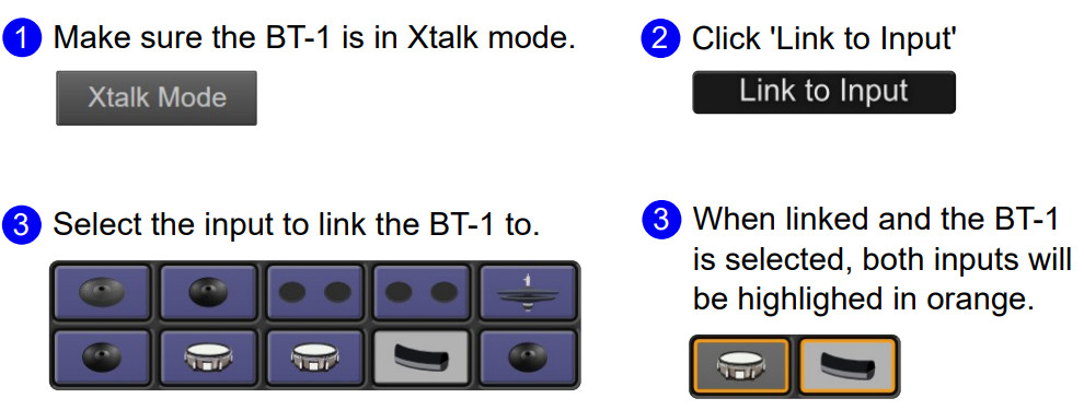
Xtalk Mode
If your BT-1 is connected directly to another pad, you will likely need to use it in Xtalk mode in order to prevent the BT-1 from mistriggering when you hit the pad it’s attached to. In order to use Xtalk mode, the BT-1 must be setup on a stereo input.
Link to Input
When using Xtalk mode, you can link the BT-1 to another input. This prevents the input from mistriggering when you hit the BT-1. The link another input, follow the diagram below.
When linked to a dual piezo type pad, only sidestick articulations will be filtered out, so the BT-1 and the head or rimshot of the snare can still be simultaneously triggered. For switch based pads, only the BOW or HEAD articulation will be filtered out.
Adjusting Crosstalk Cancellation To Linked Input
Once the BT1 is linked, the crosstalk control no longer applies crosstalk cancellation to the BT1, instead, the crosstalk control applies an extra amount of crosstalk to the linked input. The default value of 15 should be good for most setups. Applying too much crosstalk to the linked input will affect the ability for linked pad to accurately trigger when the two pads are hit simultaneously.
Preset Manager
The Preset Manager allows you to quickly load settings for your pads and pedals. It comes with factory presets for many commercially available pads and hihat controllers, but also allows you to create, import, and export your own presets.

Preset Types
By clicking on icons at the top of the UI, you can switch between viewing device snapshots, trigger presets, pedal presets, or drum maps. Device presets stored on a USB flash drive are special and described here.

Trigger presets, pedal presets, and drum map presets are further ![]() broken down into ‘Factory’ and ‘User’ presets.
broken down into ‘Factory’ and ‘User’ presets.
Finding Presets
You can easily find a preset for your pad using the search function or with the Brand and Type filters. Next to each filter is a number that indicates how many presets are associated with that filter. Clicking on an active will remove it.
Loading a preset
Double-click a preset to load it. Upon confirmation, the preset is sent to the device replacing existing settings. If Auto Save is on, the preset is saved to the device’s memory. If Auto Save is off, power cycling the device will restore your previous settings.
Loading Trigger and Pedal Presets
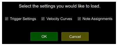
Factory presets load all the settings for an input except note assignment.
When loading user presets however, a dialog box allows the user to chose which settings to load.
Loading Device Snapshots
By default, all the settings will be loaded, but by clicking ‘Use custom load option’ the user can specify which parts of the snapshot to load, or inputs to apply settings to.
In the example on the right, only the input settings for the first pedal input will be loaded. All the other settings in the snapshot will be ignored.
The load option are saved inside the preset, so whenever you make changes, you will need to save the preset by clicking on the save icon in the upper right corner.
If ‘Drum Map’ is checked, the drum map will also be sent to any eDRUMin devices connected the USB host port.

Send MIDI
Upon loading a snapshot, you can have the eDRUMin send a program or control change message to keep external hardware / software in sync with your snapshot changes.
Working with User Presets
When you select a user preset, a set on icons appear to the right.

![]() Updating a Preset
Updating a Preset
When you click this icon, the settings for the selected input or device are re-downloaded and stored into the preset, overwriting the previous settings. The metadata for the preset preserved.
![]() Exporting a Preset
Exporting a Preset
This exports the preset, which has a file extension .edp, to your desktop. A notification showing the name of the file is displayed. You can then backup that preset or share it with others.
![]() Editing Metadata
Editing Metadata
Edit the metadata for a preset without changing the contents of the preset itself.
![]() Deleting a Preset
Deleting a Preset
Click to delete a preset. A confirmation dialog is displayed.
Creating User Presets
A new user preset is created by clicking on the ‘New Preset’ icon.

The settings from the device are then downloaded and stored to your computer. A dialog box is displayed and allows you to set metadata for the preset.
Carefully setting the metadata is highly recommended, especially if you plan to share your presets with others.
There is no need to save your device settings before creating a user preset. The preset will always include any unsaved changes.
Importing Presets
A preset can be imported into your user presets by dragging and dropping an .edp file onto the Preset Manager. A notification is displayed and the preset is added to the list of User Presets.
Device Snapshots on USB Flash
eDRUMin 10 includes a USB host port and by connecting a USB flash drive to this port, you can save device snapshots to it.
The advantage of saving device snapshots to a flash drive is that they can be loaded using an attached footswitch or sustain pedal or MIDI Program Change messages (Channel 14, values 1-32) without having the eDRUMin Control Application open or even having the eDRUMin connected to a computer.
If the flash drive icon with a flashing red ‘x’ appears, this indicates are error using the flash drive.![]()
You can create a new flash device snapshot by clicking the ‘New Preset’ icon or by duplicating an existing snapshot.

The snapshots are saved as an ordered list. You save up to 32 snapshots on the flash drive and they can be reordered by dragging snapshots up and down through the list.
Look here for information on how to load flash preset using a pedal.
Drum Map Editor
Drum maps allow your eDRUMin to easily switch between triggering between different hardware / software applications.
eDRUMin comes with several factory drum maps, but users can also create and edit their own maps with the Drum Map Editor which is integrated into the Preset Manager. Click on the drum map button, shown right, to view, load, or edit the drum maps on your system,

To start editing a drum map, either click ![]() to create a new user drum map from the one already stored on your device, or duplicate a factory preset.
to create a new user drum map from the one already stored on your device, or duplicate a factory preset.
When you duplicate a factory preset, it’s automatically placed in your user presets and selected for editing.
After editing a drum map, you must save it by clicking on the white save icon in the top right hand corner of the editor.

Once saved, double-click on the drum map to send it to the device. If you have more than one device connected to your system, the map will be sent to whichever device is currently selected.
You can have drums sent to all connected device by clicking on the eDRUMin logo and selecting ‘Send drum maps to all devices,’ turning its icon green.
After enabling this option, loading a drum map will send it to all eDRUMin devices connected to your computer.
A drum map is broken up into two pages of kit pieces (32 total) and a page for hihat pedal / cymbal.
Page 1 Kit Pieces
Each kit piece has four notes associated with it. The labeling of the notes depends on whether the image associated with the kit piece is a pad, cymbal, or percussion.
The first three notes are the standard 3 zones that most pads and cymbals can trigger, but the forth note’s function varies depending on an input’s settings.
If the input supports positional sensing, then this will correspond to the positional CC that the pad should use.
If the pad type is a cymbal and the choke label is enabled, then this note represents a choke note that is sent along with aftertouch. Look here for more information about enabling choking with notes.

Page 2 Kit Pieces
 While the page 1 kit pieces will be sufficient for 95% of users, Page 2 kit pieces are for those with more complex setups.
Page 2 lets you define an additional 16 kit pieces, and unlike the page 1 which has predefined images, the images for kit pieces on page 2 can be changed.

To change a kit piece’s image, right click on it and select an image from the list of available images.
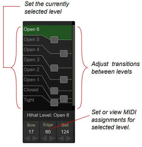
Hihat Pedal / Cymbal
The hihat section defines the notes that pads set to ‘Hihat Cymbal’ will trigger when the hihat is in Levels Mode. If the hihat is in CC Mode, then pads set the ‘Hihat Cymbal’ will trigger the notes defined by the hihat kit piece from Page 1 kit pieces.
By clicking on the various levels, you can adjust the notes that will be played for each level. You can drag and drop levels onto each other to quickly copy assignments.

Drag and Drop
Drag and drop is supported within a drum map, and also between drum maps.
For example, you can drag one kit piece onto another to copy its note assignments. The same goes for hihat levels.
You can drag one hihat level onto another to copy note assignment.
You can also drag kit pieces, hihat levels, all pads, and all hihat settings between drum map presets. When you do this, the target preset is updated and saved immediately.

Pedal Editor
The pedal input(s) on the back of the eDRUMin supports a wide array of pedal types including hihat controllers, expression pedals, sustain pedals, and footswitches. You can open the pedal editor by clicking pedal input icon at the top of the UI.

Pedal Type
The pedal input can perform different functions depending on the type of pedal it is setup for. By default it’s setup for a Roland style hihat controller. If you are using a Yamaha compatible hihat controller, you will need to the wiring style to “Yamaha”.
Some hihat setups will need custom settings. Here are specific instructions for the Roland VH-12 and Hall effect sensor based pedals.

You can change the pedal type by clicking on the hihat controller icon.
Settings for Hihat and Expression pedals is described on the following page. Settings for footswitches and sustain type pedals is described here.
If you set the pedal type to ‘Auto Detect’, make sure you you connect your cable to the pedal pedal / controller before connecting it to the eDRUMin.
Hihat Controllers and Expression Pedals
When a hihat or expression pedal is connected, it is automatically setup to send out CC messages for the position of the pedal, and velocity sensitive closed hihat notes and splash articulations.
If using a hihat controller on a real hihat stand, make sure it is properly setup before adjusting any other settings.
Calibrating Your Pedal
You should calibrate your pedal even it seems to working fine when you first connect it. eDRUMin auto calibrates the pedal and won’t lock in calibration settings until you go though the calibration process.
Click Calibrate to reveal the calibration range. Take the pedal through its full range of a motion. When done, click the calibrate control again to store the settings.
The calibration can be overridden by dragging either side of the green range indicator.

If you are using a hihat on a hihat stand, making adjustments to the tension of your hihat stand and clutch position will likely require you to re-calibrate your hihat controller for optimal results.
Modes for Expression Pedals and Hihat Controllers
By default expression pedals and hihat controllers will function as hihat controllers in CC mode as shown in the image below.
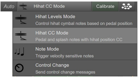
By clicking on the Mode control, you can change what the pedal does.
Only the two Hihat Modes are discussed in this manual. The other mode are more intuitive and if you want more information about them, please consult the MIDI Expression User Manual.
Note Source
Like trigger inputs, a hihat pedal can get its note assignments from the device drum map, or it can be set to ‘Custom Notes’. When set to Custom Notes, the CC, Pedal and Splash are independent of the device drum map.

This setting also affects any trigger inputs that are set ‘Hihat Cymbal’. If this is set to ‘Custom Notes’, than those pads that are set to ‘Hihat Cymbal’ will also use their ‘Custom Note’ assignments and not the notes defined in the drum map.
CC Mode vs. Levels Mode
A hihat controller has two basic functions. First, it communicates the position of the hihat pedal so that hihat sounds can vary in terms of their openness, and second it triggers velocity sensitive pedal and splash notes when you press the pedal all the way down.
CC Mode and Levels Mode handle triggering pedal and splash notes in the same way, but differ in the way they handle communicating the hihat position.
CC Mode
CC Mode sends out a CC message corresponding to the position of the pedal. Many applications can use this CC to determine which hihat sound to trigger.
The Curve control allows you adjust the dynamics of the CC message values.
It can be turned on and off by simply clicking in the background of the control.
You use the Bezier handles to adjust how fast the hihat opens and closes when you press the pedal.
The MIN control allows you to simulate a hihat, clutch, allowing you to restrict the amount of openness when the pedal is fully released.

Levels Mode
With Hihat Levels Mode, eDRUMin takes more control over which hihat sounds are triggered by using different sets of MIDI notes for the hihat cymbal depending on the position of the pedal. This mode is suitable if you require more control over the transitions between your hihat sounds or for applications and devices that do not process CC4 messages.
To work properly, the input your hihat cymbal is connected to must be set to ‘Hihat 1 Cymbal’ or ‘Hihat 2 Cymbal, depending on the pedal input you are using.

Adjusting the Responsiveness Closed Hihat Notes and Splashes Controller Type
![]() There are two algorithms for triggering closed pedal notes. ‘Pedal’ is for setups that use a detached hihat pedal (ex. Roland FD-8, Yamaha HH65), and ‘Stand’ for setups that use a real hihat stand (ex. VH-10, ATV AD-H14)
There are two algorithms for triggering closed pedal notes. ‘Pedal’ is for setups that use a detached hihat pedal (ex. Roland FD-8, Yamaha HH65), and ‘Stand’ for setups that use a real hihat stand (ex. VH-10, ATV AD-H14)
Travel
The travel control determines where along the pedals travel the velocityfor a closed pedal note is calculated. In the image on the right, the line traces the position of the pedal over time. The pedal must pass into the green area in order for a note to be generated.
If you are using a two piece hihat like a Roland VH-13, make sure the green area is a little above the point where the two hats come together.

Splash Sensitivity
Any time a pedal note is triggered, a splash note can also be trigger if the pedal reopens quickly enough. The height and width of the green box in this control is used to adjust the sensitivity.
A splash note will be triggered the moment a pedal transient travels up and out of the box like it does in the picture on the right. The width of the box sets the maximum time window in which a splash can be triggered, and the height determines how far the pedal must reopen.

Threshold
The threshold control sets a minimum amount of force required to trigger a pedal / splash note.

Gain
Turn up the gain control to increase the velocity of your pedal / splash notes.
xTalk
If when pressing down on your hihat pedal causes your hihat cymbal to trigger, you can use the xTalk control to filter out those false triggers. The meter measures the signal on your hihat cymbal. Set the control above the meter to make sure it’s filtered out.
SteadyHats
SteadyHats is designed to hold your hihat position steady immediately after hitting the hihat cymbal. If you cymbal pad is mounted on a hihat stand, then hitting the cymbal will cause the hihat position to change very suddenly. These sudden position changes can cause unwanted audio artifacts in some applications.
The green meter shows the maximum amount of movement that will be filtered. The indicator inside the meter shows the amount of movement that was filtered out after the last hit. If the indicator moves past of the green area, filtering will stop until the next hit.
Velocity Curve
The velocity Curve control allows you to shape the velocity response of pedal and splash notes. It works exactly like the one for trigger inputs. Look here for more information.

Impact Method (Advanced Mode)
If you device is in Advanced Mode, you can use the ‘Impact’ method of triggering close hihat pedal notes. With this method, the velocity of pedal notes is determined by the vibrations of the hihat cymbals as they come together when the hihat pedal is pressed. It’s very important that your hihat trigger settings are optimal. Poor choice of threshold and hit decay values will affect the ability to accurately trigger the closed hihat pedal articulation.

Hihat pedal Thresh
This needs to be set very carefully. Setting it too low will cause false triggering when your hihat cymbals move, and setting it too high will result in missed pedal events.
 To make adjustments, use the yellow meter. The thresh setting will be optimal when the meter shows 5% to 20% while pressing the pedal to trigger the close hihat pedal note, like it does in the image on the right.
Scaler
The scaler control is used to determine the velocity of a close hihat pedal articulation. Increase the value of the control to to get higher velocity notes. The meter in this control displays the final velocity of the notes.

Advanced Hihat Options
For most users, these options should be left unchecked.
They are advanced options most users do not need to be concerned with and can produce unwanted results.

Fast Stepping Fix
In some drum triggering software applications, most notably Superior Drummer, rapid up and down movements of the hihat pedal can cause strange audible artifacts due to the way it transitions between hihat samples.
One way to remove these artifacts is to stop sending CC position values for a short period of time after a closed pedal note. Checking this box will do exactly that.
Only send CC with Hit
Superior Drummer will attempt to transition between hihat samples whenever the hihat pedal is moving. Most people regard this as a feature as it provides a more natural sounding hihat is most situations, but others do not like the subtle artifacts that it produces. By checking this checkbox, eDRUMin will only send the hihat positional CC just before a hihat note is sent. This effectively prevents the Superior Drummer from being able to transition between hihat samples at all.
Setting up VH-12 and Hall Effect Sensors
Roland VH-12
Most Roland Hihat controllers can be sensed automatically, however the VH-12 is a bit of a unique beast. To get it to work properly, use the VH-12 factory preset or set it up manually as described below.

Hall Effect Sensors
eDRUMin is compatible with hall effect sensors. While the pedal sensing feature can properly detect some Hall effect sensor setups, you will likely need to set things up manually.
Self-Powered
If your Hall effect sensor is self or externally powered, the pedal type needs to be set to hihat and the polarity set to Roland, just like for the VH-12 mentioned above.
Requires Power From Jack
If your Hall effect sensor needs power from the eDRUMin, the pedal input type needs to be set to ‘Expression’. The POLARITY control determines the function of the tip and ring connections.

Look here for a recommended Hall effect sensor and wiring diagram.
Sustain Pedals and Footswitches
When a sustain or dual footswitch is plugged into pedal input of the eDRUMin, the pedal is automatically configured to change the Note Bank for the currently selected input, however for it to work properly, your device will need to be in advanced mode.

Using a Latching Type Footswitch
By default, the input is setup to be used with momentary type switches. If you are using a latching style footswitch, change the SWITCH TYPE to ‘latching’
Modes for Sustain Pedals and Footswitches
A sustain pedal or footswitch doesn’t have to be used for Bank Changes. These types of pedals are able to send many kinds of MIDI messages. You can change the MODE of your pedal clicking on the MODE button.

As most eDRUMin users will only be using the Bank Change or Flash Preset Change modes, these are the only modes described in this manual.
For me information about the other available modes, consult the MIDI Expression Manual.
Using a Pedal for Bank Changes
When your device is in Advanced Mode, each input has 4 banks of MIDI notes associated with it. These banks can be controlled using a pedal plugged into the pedal input on the back of your device.
When you attach a footswitch or sustain pedal, it is automatically setup to perform Bank Changes for the selected input (the the pad that was last hit). Press the pedal quickly to select the next bank. Do a long press to select the previous bank.
Note: For a dual fooswitch the two buttons are linked by default. This means that one button will select the next bank and the other will select the previous.
Bank Change Logic
There are three ways you can change banks. You can send bank changes for all inputs at the same time, to a single input, or to the currently selected input. Use the INPUT control to select which input(s) to send Bank Change messages to.

Send to Currently Selected Input
The lowest value is ‘Cur’ and means the bank change messages will be sent to the currently selected input. The idea is that you hit a pad to ‘select’ it, and then press the pedal to change its bank. If you have another eDRUMin connected to the USB host port, the bank change will only be sent to the selected input of the selected device.
Send to a Single Input
Perhaps you only need to change to bank of a specific input without needing to worry about weather it’s selected or not. Using the input values 1-4 (ED4) or 1-10 (ED10), you can send bank change messages to specific inputs. When sending to a single input, the bank change will never be sent to other eDRUMin devices connected to the USB host port.
Send of All Inputs
Use the greatest setting ‘ALL’ to send the bank change messages to all inputs, including all the inputs of any devices connected to the USB host port of an eDRUMin 10.
Note: Hihat controllers also have 4 banks associated with them. If your hihat controller is linked to a trigger input, the banks for the hihat pedal will change whenever the bank for the input it’s linked to changes.
Bank Select Range
The MIN and MAX controls allow you to specify the range of banks to use. The bank selection wraps around so if you increment past MAX, it’ll wrap around to bank MIN and vice versa. So if you set the MIN to 1 and MAX to 2, pressing the button on your pedal will alternate between those two banks.
Flash Device Snapshot Change
If you have an eDRUMin 10, you can connect USB flash memory to the USB host port and save device snapshots to it. Then using a footswitch or sustain pedal, you can load those snapshots without needing to have the control application open or the device connected to a computer.
Select ‘Flash Preset Change’ by clicking on the mode button.

By default the Flash Snapshot Change mode will be setup to switch back and forth between two flash snapshots. If you are using a momentary type footswitch, make sure you enable to the toggle control as shown in the image on the right.

If you enabled the ‘+/-’ option, you can have the pedal scroll through a range of snapshots every time you press it. Use the MIN and MAX to specify the range. Quickly pressing the switch will load the next snapshot, and long pressing will load the previous snapshot.
In the screenshot above, the first switch alternates between loading snapshot 1 and 2, and the second switch will cycle between loading snapshots 3, 4, and 5.
MIDI Monitor
The MIDI Monitor allows you to see the MIDI data moving through the device allowing you to see where it originates, and where it goes.
Click the ![]() icon to show the MIDI Monitor.
icon to show the MIDI Monitor.
It has a 1000 event history and is scrollable. To function efficiently, messages do not arrive in real-time. They are buffered and sent in packets and can arrive up to 100ms after the actual MIDI event.
 Source and Destinations
This indicates where a MIDI message arrivesfrom and where it goes to. Trigger inputs are labeled 1-10, pedal inputs are P1 or P2, ![]() is device’s USB port,
is device’s USB port, ![]() is the MIDI DIN, and
is the MIDI DIN, and ![]() is the USB Host port.
is the USB Host port.
The background of events are also color coded by their source. Trigger input messages are grey, pedal input messages are bluish grey, USB host port messages are green, USB MIDI messages are orange, and DIN MIDI messages are purple.
Scroll
When you use the mouse wheel to scroll though the events in the monitor, the autoscroll button gets deactivated to prevent newly arriving events from changing the current position in the log. Activating ‘Scroll’ will then jump to the end of the list allowing you to see any new events.
Filter
On by default, this filters out Active Sensing, MIDI Clock, and Note off messages. The vertical bar in the middle of the icon will flash when messages are actively being filtered.
eDRUMin USB Host Port and MIDI Ports

The eDRUMin 8 and 10 come with a USB host port for connecting additional eDRUMin devices and/or USB MIDI devices. The host eDRUMin and any devices connected to it function as an aggregate device, complete with crosstalk cancellation between devices.
Connecting a USB hub to the host post allows you to connect up to four additional devices. The USB Host port only supplies up to 500mA of power. If you are using a hub and require more than 500mA, be sure to use a powered hub.

The Flow of MIDI Messages
By default, MIDI generated by each device is forwarded to all the other connected devices.
Imagine that we have an eDRUMin 10 connected to a computer via USB. Additionally we have an eDRUMin 4 and a Yamaha drum module connected via a USB hub to the eDRUMin USB host port.

The following statements describe what happens to the MIDI.
- The MIDI from the eDRUMin 10, the eDRUMin 4, and the Roland module are processed by the eDRUMin 10.
- Crosstalk cancellation is applied to the MIDI to ensure unintentionally triggered MIDI notes are filtered out.
- The filtered MIDI from each device is then forwarded on to each of the other connected devices.

This behavior allows the eDRUMin 10, eDRUMin 4, and the Yamaha module to act as one aggregate device with respect to the computer. At the same time, the eDRUMin 10 and eDRUMin 4 can simultaneously trigger sounds on the Yamaha module.
If connecting a Roland drum module with Local Control disabled, see the next page to ensure that the MIDI it generates is sent back to itself.
Processing External MIDI
This page allows you to adjust crosstalk cancellation for external sources of MIDI and adjust MIDI routing settings for individual sources.
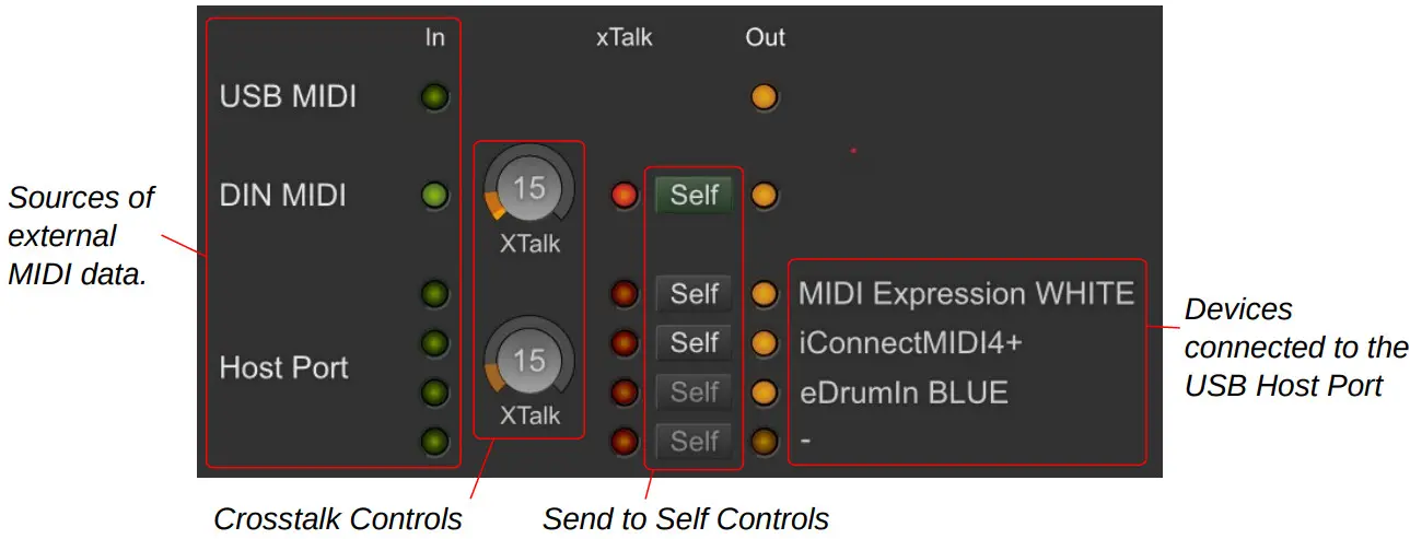
Crosstalk Cancellation
When pads connected to a common structure are processed by separate devices, crosstalk can be an issue. The tom pad in the image on the right is connected to an input of an eDRUMin 10 and the cymbal is connected to an eDRUMin 4, which is connected to the ED10 via the MIDI DIN IN port.
When the tom pad is hit, the ED4 also triggers a note because the two pads share a common structure.

This crosstalk can be filtered out using the crosstalk cancellation controls.
When we hit the tom pad, the MIDI DIN In LED lights indicating MIDI activity from the ED4. The meter in the xTalk control lights up indicating that the ED10 detected crosstalk. Because the xTalk control is set higher than the measured crosstalk, the Note On/Off messages are filtered and the red led lights up.

In this example, we can see that we can safely reduce the crosstalk control substantially. Typically pads connected to separate devices are physically isolated, so xTalk can be turned all the way down.
Send To Self
![]() By default, when a device connected the eDRUMin generates MIDI data, that data is sent to all other connected devices, but it is not back to itself. This is done to prevent the possibility of creating MIDI feedback loops. In some circumstances you might want the MIDI to be returned to the source. If, for example, you are using a Roland module and have “Local Control” disabled, you will need to send the MIDI back to the source in able to hear the sounds back on your module. Enable the ‘self’ button for a MIDI source to have its crosstalk processed MIDI sent back to it.
By default, when a device connected the eDRUMin generates MIDI data, that data is sent to all other connected devices, but it is not back to itself. This is done to prevent the possibility of creating MIDI feedback loops. In some circumstances you might want the MIDI to be returned to the source. If, for example, you are using a Roland module and have “Local Control” disabled, you will need to send the MIDI back to the source in able to hear the sounds back on your module. Enable the ‘self’ button for a MIDI source to have its crosstalk processed MIDI sent back to it.
Updating Firmware
The eDRUMin firmware is periodically updated to add new features or fix bugs. The latest firmware for eDRUMin is always included with the eDRUMin Control application.
![]() The firmware can be updated or changed by clicking on the Firmware Update icon located at the bottom of the sidebar. Please note that the iOS version of the Control Application does not support updating device firmware.
The firmware can be updated or changed by clicking on the Firmware Update icon located at the bottom of the sidebar. Please note that the iOS version of the Control Application does not support updating device firmware.

Changing Colors
If you have more than one eDRUMin of the same color connected to the same computer, you might want to change the ‘color’ of one of the devices in order to change the name of its MIDI port to prevent your host sequencer and yourself from getting the devices mixed up.
Calibrate Noise Floor
This function analyzes and calibrates the eDRUMin inputs to minimize the floor noise and maximize input sensitivity. Re calibrate the noise floor after performing a factory reset.
For first generation ED4 (plastic casing), make sure pads are connected to all the trigger inputs before calibrating.
Disable Compatibility Check
Normally, eDRUMin checks to make sure piezo / switch type pads are properly wired and will disable an input if it detects an issue. If you feel the device is incorrectly detecting an issue with one of your pads, you can disable this compatibility checking.
Factory Reset
The wipes the device’s memory and resets all settings to default.
iOS Control Application
The control application is available as an iOS app from the Apple App Store.
Getting Connected
The iOS version of the Control Application can communicate with the eDRUMin using the camera connection kit, or Network MIDI,
When the Control Application is opened, any connected to devices will automatically be detected. You can manually re-sync devices by clicking on the refresh icon.

Camera Connection Kit
Using the Apple Camera Connection kit, you can connect a eDRUMin directly to your iOS device. Using a USB hub is also supported, but if you plan to connect more than 2 eDRUMin devices, it will likely need to be a powered hub.
![]() Simply plug in the devices and the Control Application should find them automatically.
Simply plug in the devices and the Control Application should find them automatically.
Network MIDI
![]() You can also use the iOS Version of the Control Application to remotely control eDRUMin devices connected to a computer on your local network.
You can also use the iOS Version of the Control Application to remotely control eDRUMin devices connected to a computer on your local network.
This is done using the Audio MIDI Setup
- Open the Audio MIDI Setup, found in Utilities.

- From the “Window” menu, select “Show MIDI Window”.
- Double click on the “Network” object.

- Click on the + sign to create a new session.
- Give it a meaningful name and check the checkbox to enable it.
- Setup the Live Routings. Be careful to pick the right MIDI Inputs. Do not chose the ‘Network’ MIDI connections.
- Open the Control Application on your iOS device.
- Select your iPhone or iPad.
- Click on the Connect button.
The Control Application should automatically find and connect to your eDRUMin. You’ll need to create and connect to a different session for each eDRUMin you want to connect to over the network.
About Power in iOS
iOS powers down USB devices when it goes to sleep. If you would like to keep your eDRUMin powered and running, you can enabled the ‘Keep Device Powered’ switch from the sidebar.

This will keep the iOS device awake and the eDRUMin powered as long the eDRUMin is actively being used. If no activity is detected for 1 minute, the iOS sleep function is re-enabled and the device will go to sleep as normal.
You can also chose to power the device with an external 9V power adapter while connected to iOS. This keep the device powered and functional even after the iOS device goes to sleep.
Appendix
Working With Multiple Devices on Separate USB Ports
You can connect as many eDRUMin devices to the same computer as you have USB connections. Each eDRUMin 4 needs about 70mA and each eDRUMin 10 needs about 100mA, so you should be fine using a standard unpowered 4 port USB hub. Updating the
firmware while connected though a hub is not recommenced.
Managing Crosstalk Between Devices
Because multiple eDRUMin devices connected to separate USB port don’t have any direct connection, crosstalk issues can occur when two adjacent pads, connected to the same mounting structure, are connected to separate eDRUMin devices.
There are two ways to avoid crosstalk problems. One way involves physical isolation of pads and cymbals, and the other involves routing MIDI from one device into the other.
Physical Isolation
Any pads connected to a common structure will experience crosstalk and so should be connected to a single eDRUMin so that the device can prevent this crosstalk from causing mistriggers. Pads and cymbals that use separate stands will not experience any crosstalk and therefore can be connected to a second unit without causing any mistriggering.
Crosstalk Cancellation via USB MIDI In
 In some situations, physical isolation is not possible. In these cases, the only option for processing crosstalk between devices is to route MIDI from each device into each other device.
Because this method involves complicated MIDI routing, the only support I offer is a screenshot of the routing in Ableton Live.
How this is accomplished in various hosts differs, but the general concept is the same.
The first track is the MIDI from both eDRUMin devices, which is sent to Superior Drummer.
The second track routes MIDI from the BLACK eDRUMin to the BLUE eDRUMin.
The last track routes MIDI from the BLUE eDRUMin to the BLACK eDRUMin.
There’s no need to record the MIDI used for crosstalk processing, but the tracks do need to have monitoring enabled.
Controlling Banks with MIDI Program Change Messages
A connected sustain pedal or dual footswitch is perfect for controlling banks of notes. If your pedal input is being used by a hihat controller, you can still configure a 3rd party MIDI device to send program changes into the eDRUMin via its USB port.
The MIDI channel of the program change message determines which input should change its bank. The value of the program change says how the bank should change.
Use MIDI Channel to Target Input
Banks Changes can be sent any individual input, the selected input, or all the inputs.
The MIDI channel of the program change message determines which input it is sent to.

The ‘Selected’ input is typically the last active input. If you hit a pad connected to input 1, then input 1 becomes the selected input. If you then hit a pad on input 3, input 3 becomes the selected input.
Use Program Change Value to Specify Operation
The value of the Program Change message determines what it will do. It can select a specific bank, or increment / decrement a bank.
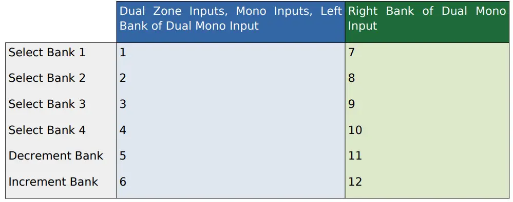
Note: Inputs that are setup as Dual Mono have two sets of banks associated with them—one for each pad.
To target the banks for left half of the input, use the first set of operations. To target the banks for the right half of the input, use the second set of operations.
Setting up your Hihat on its Stand
To get the best performance possible from your hihat, it’s important that it’s setup properly on its stand. You know your setup is good when every slight movement of your hihat pedal registers in the Control Application. I’m going to go over setting up a Roland
VH-10 as an example.
Adjusting the hihat clutch
Setting the height of your hihat correctly is very important for eliminating crosstalk between the hihat pedal and the hihat cymbal. If you set the hihat too high, the sensor on your hihat controller will not be able to detect when you very slightly press down on your hihat pedal. For optimum performance, the hihat cymbal should always be in contact with the plunger on the VH-10 controller.

Adjust the knob at the top of the cymbal
This knob allows you to adjust how much pressure is required to have to pedal register completely closed.
Turning clockwise makes it more pressure sensitive and turning it anti-clockwise makes it less pressure sensitive.
For optimal performance with eDRUMin devices, turn the knob almost as much as it can go in the clockwise direction.

This allows the eDRUMin to more accurately track the position of the pedal, and also makes your hihat responsive to the amount of pressure you’re applying when in the fully closed position.
Calibrating
After the hihat is setup properly on its stand, the next step is to calibrate it within the control application. Simply press the calibration button and press all the way down on your pedal, as hard as you would normally expect to have to press it. Make any final adjustments with the mouse. Make sure the red position indicator is even or further to the right of the green calibration rectangle when you foot is removed from the pedal.

Tips For Working with Audiofront Controls
The page contains some bits of information that can improve your workflow when using Audiofront software.
General Tips
- Use SHIFT modifiers for more precision.
- Use the mouse wheel for fine adjustments.
- Double-click to set defaults.
Working with Note Controls
 The values of these controls can be changed in a variety of ways.
- Drag the value up and down.
- Use the increment or decrement arrows.
- Double-click a control and enter the value as a note name ‘C3’ or as a note number ‘60’.
You can switch between displaying note numbers and note names by right clicking a note control (long press to touch devices). This will cause all note controls to change and the setting is saved and restored the next time you open the control application.
For controls that represent musical notes, the device will audition the notes as they are changed, allowing you to setup and test note assignments without any pads connected.
Troubleshooting
If this section doesn’t cover your issue, consider checking the troubleshooting and technical support users forums for more help and information.
If you are having MIDI related problems, the built-in MIDI Monitor can help you track down MIDI and routing related issues.
Common Problems
Compatibility issue

If you see an orange exclamation mark appear next to an input, it means that the eDRUMin has detected a piezo when it expects a switch and that you most likely have selected the wrong pad type for the pad that is plugged in.
This could also be the result of a jack not being plugged in all the way, a damaged cable, or a damaged or pinched switch.
These issues are most common with DIY and metal cymbals.
If using a metal cymbal, make sure it is configured correctly. For example, you might get a compatibility issue your cymbal is set to ‘Bell is Switch’ when your cymbal actually uses a piezo for the bell.
Although not recommended, you can disable the ![]() compatibility check from the firmware update section.
compatibility check from the firmware update section.
Hihat Problems
Because eDRUMin supports so many different hihat technologies, it can sometimes have trouble auto-detecting different hihat setups, especially for users using non-standard setups.

You can eliminate some possible sources of problems by disabling pedal sensing and specifying the polarity of your hihat pedal / controller.
USB Flash Memory Problems
![]() USB flash drives require a lot of power. If your eDRUMin is unable to read from the flash drive, it is likely due to a power issue. If you have a USB hub connected to your eDRUMin 10 host port with multiple devices connected to the hub, you will need to ensure your setup has enough power. Here are some suggestions:
USB flash drives require a lot of power. If your eDRUMin is unable to read from the flash drive, it is likely due to a power issue. If you have a USB hub connected to your eDRUMin 10 host port with multiple devices connected to the hub, you will need to ensure your setup has enough power. Here are some suggestions:
- Power the ED10 via an external power adapter.
- Connect the ED10 to a powered USB hub using a very short USB cable.
- Connect a powered USB hub to your ED10 host port.
Drum Pad Wiring Diagrams

Pedal Input Wiring Diagrams

![]() Voltage on pedals inputs should be in the range of 0V to 3.3V. If externally powering a pedal input, you risk damaging the pedal input if the voltage goes outside of this range.
Voltage on pedals inputs should be in the range of 0V to 3.3V. If externally powering a pedal input, you risk damaging the pedal input if the voltage goes outside of this range.
MIDI Implementation
MIDI Expression MIDI Implementation

Documents / Resources
 |
audiofront eDrumin Drum Module [pdf] User Manual Version 2.3.1, eDrumin Drum Module, eDrumin, Drum Module, Module |