![]() Intelligent Input/Output Unit
Intelligent Input/Output Unit
Installation Guide

| Part No | Product Name |
| SA4700-102APO | Intelligent Input/Output Unit |
Technical Information
All data is supplied subject to change without notice. Specications are typical at 24V, 25°C and 50% RH unless otherwise stated.
| Supply Voltage | 17-35V dc |
| Quiescent Current | 500µA |
| Power-up Surge Current | 900µA |
| Relay Output Contact Rating | 1A at 30V dc or ac |
| LED Current | 1.6mA per LED |
| Maximum Loop Current (Imax; L1 in/out) | 1A |
| Operating Temperature | 0°C to 70°C |
| Humidity | 0% to 95% RH (no condensation or icing) |
| Approvals | EN 54-17 & EN 54-18 |
For additional technical information please refer to the following documents which are available on request.
PP2553 – Intelligent Input/Output Unit
![]() Drill holes where required.
Drill holes where required.
![]() Do not over tighten screws
Do not over tighten screws
![]() Remove knockouts and tglands where required.
Remove knockouts and tglands where required.

![]() Do not over tighten screws
Do not over tighten screws
![]() The 8th segment must be in set to ‘0’ for Discovery / XP95 operation
The 8th segment must be in set to ‘0’ for Discovery / XP95 operation
![]() All CI tests must be carried before connecting the interface. For connectivity instruction see Figs 1, 2 & 3
All CI tests must be carried before connecting the interface. For connectivity instruction see Figs 1, 2 & 3
![]() Note the alignment marks
Note the alignment marks

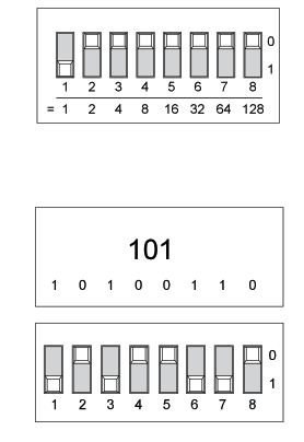
Addressing
| XP9S / Discovery Systems | CoreProtocol Systems | ||
| Segment I | 1 | Sets the address | Sets the address |
| 2 | |||
| 3 | |||
| 4 | |||
| 5 | |||
| 6 | |||
| 7 | |||
| 8 | Set to ‘0’ (Fault value is returned if set to ‘1’) | ||
| FS | Enables failsafe mode (compliant with 13S7273-4 for door holders) | Enables failsafe mode (compliant with B57273-4 for door holders) | |
| LED | Enables/Disables LED (except Isolator LED) | Enables/Disables LED (except Isolator LED) | |
Note: On mixed systems addresses 127 and 128 are reserved. Refer to system’s panel manufacturer for further information.
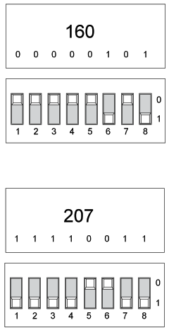
Address Setting Examples
 |
 |
Connectivity Examples


 When operated under XP95 or Discovery Protocols, EN54-13 type 2 devices can be connected. In case EN54-13 type 1 devices need to be connected they must be installed directly next to this module, with no transmission path according to EN 54-13.
LED Status Indicator
| RLY | Continuous Red | Relay Active |
| Continuous Yellow | Fault | |
| POLL/ ISO |
Flashing Green | Device Polled |
| Continuous Yellow | Isolator Active | |
| IP | Continuous Red | Input Active |
| Continuous Yellow | Input Fault |
Note: Not all LEDs can be on simultaneously.
Commissioning
The installation must conform to BS5839–1 (or applicable local codes).
Maintainence
Removal of the external cover must be carried out using a at screwdriver or similar tool.
Caution
Unit damage. No electrical supply greater than 50V ac rms or 75V dc should be connected to any terminal of this Input/Output Unit.
Note: For compliance with Electrical Safety Standards the sources switched by the output relays must be limited to a 71V transient over-voltage condition.
Contact Apollo for more information.
Troubleshooting
Before investigating individual units for faults, it is important to check that the system wiring is fault free. Earth faults on data loops or interface zone wiring may cause communication errors. Many fault conditions are the result of simple wiring errors. Check all connections to the unit.
| Problem | Possible Cause |
| No response or missing | Incorrect address setting Incorrect loop wiring |
| Incorrect address setting Incorrect loop wiring |
Incorrect input wiring Incorrect wiring Control panel has incorrect cause and effect programming |
| Relay energised continuously | Incorrect loop wiring Incorrect address setting |
| Analogue value unstable | Dual address Loop data fault, data corruption |
| Constant Alarm | Incorrect wiring Incorrect end-of-line resistor tted Incompatible control panel software |
| Isolator LED on | Short-circuit on loop wiring Wiring reverse polarity Too many devices between isolators |
Mode Table*
| Mode | Description |
| 1 | DIL Switch XP Mode |
| 2 | Alarm Delays |
| 3 | Output and N/O input (can be equivalent for Output only) |
| 4 | Output and N/C input |
| 5 | Output with Feedback (N/C) |
| 6 | Failsafe Output with Feedback (N/C) |
| 7 | Failsafe Output without Feedback |
| 8 | Momentary Input Activation Sets Output Relay |
| 9 | Input Activation Sets Output |
*CoreProtocol enabled systems only
![]() © Apollo Fire Detectors Limited 20Apollo Fire
© Apollo Fire Detectors Limited 20Apollo Fire
Detectors Limited, 36 Brookside Road, HPO9 1JR, UK
Tel: +44 (0) 23 9249 2412
Fax: +44 (0) 23 9
Email: techsalesemails@apollo-re.com
Website:
Documents / Resources
 |
apollo SA4700-102APO Intelligent Input-Output Module [pdf] Installation Guide SA4700-102APO Intelligent Input-Output Module, SA4700-102APO, Intelligent Input-Output Module, Input-Output Module, Module |