![]() CMM366-4G
CMM366-4G
CLOUD MONITORING COMMUNICATION MODULE
USER MANUAL SMARGEN (ZHENGZHOU) TECHNOLOGY CO., LTD.
![]() Registered trademark
Registered trademark
No. 28 Xuemei Street, Zhengzhou, Henan, China
Tel: +86-371-67988888/67981888/67992951
+86-371-67981000(overseas)
Fax: +86-371-67992952
Web: www.smartgen.com.cn/
www.smartgen.cn/
Email: sales@smartgen.cn
CMM366-4G Cloud Monitoring Communication Module
All rights reserved. No part of this publication may be reproduced in any material form (including photocopying or storing in any medium by electronic means or other) without the written permission of the copyright holder.
SmartGen reserves the right to change the contents of this document without prior notice.
Table 1 Software Version
| Date | Version | Note |
| 01-09-17 | 1 | Original release. |
| 20-04-22 | 1.1 | Update the manual format, information and logo of SmartGen. |
| 09-08-23 | 1.2 | Update description of RS485 access to 120Ω resistor. |
OVERVIEW
CMM366-4G Cloud Monitoring Communication Module is 4G (fits all kinds of networks) wireless network communication protocol switch module, which can achieve gen-set (with SCI) connect to Internet. The module gains gen-set data via RS485 port, USB port, LINK port or RS232 port of gen-set controller modules of international first-class brands including SmartGen, DeepSea, ComAp, etc. Then it transmits the data to corresponding cloud server via 4G wireless network for achieving user’s real-time monitoring to running status and searching of running records via APP (IOS or Android) and PC terminal devices.
CMM366-4G module has already integrated protocols of mainstream gen-set control module. It not only can achieve gen-set monitoring but also can insert some digital alarm input/output signals to achieve monitoring of generator room entrance guard, guard against theft and fire facilities. This module, which has GPS locate function, can upload gained longitude, latitude and elevation to corresponding cloud server.
PERFORMANCE AND CHARACTERISTICS
- Connect to cloud server via 4G wireless network, one to one monitoring;
- Multiple ports for communication with gen-set control module: RS485, RS232, LINK and USB (Host); can monitor great majority gen-set control modules of international first-class brands;
- Widely power supply: DC (8~35)V, can direct use gen-set build-in battery;
- With ARM-based 32-bit SCM, high integration of hardware and strong programming ability;
- Include with GPS locate function to achieve gain location information and locate gen-set;
- Take JSON network data communication protocol, upload real-time data variation and take compression algorithm to vastly reduce network flow at the same time;
- Users can set up history data upload rest to upload monitoring data to server (history data can be analyzed);
- When alarm occurs it can upload data to server immediately;
- 2 configurable digital input ports which can receive external alarm signal;
- 1 configurable relay output port which can output various of alarm signal;
- Power and multiple communication status indicators on front panel that working status is clear at a glance;
- Lamp test function;
- Parameter adjust function: users can adjust parameters via USB port;
- Take standard π-type 35mm guide-rail installation or screw-fixed installation that the module can be installed in the gen-set control box;
- Modular design, self extinguishing ABS plastic shell, light weight, compact structure with easy installation.
SPECIFICATION
Table 2 Technical Parameters
| Items | Contents |
| Operating Voltage | DC 8.0V~35.0V, continuous power supply. |
| Power Consumption | Standby: ≤2W Working: ≤5W |
| Auxiliary Input | Digital Input, connect (B-) is active. |
| Auxiliary Output | 1A DC30V Volts free output |
| USB Host | A-type USB female port |
| RS485 | Isolated type |
| RS232 | General type |
| LINK | SmartGen exclusive port |
| USB Device | B-type USB female port |
| GPRS Port | Standard SMA port (female), SMA port (male) for antenna. |
| GPS Port | Standard SMA port (female), SMA port (male) for antenna, active antenna. |
| Wireless Network | LTE-TDD/LTE-FDD/HSPA+/TD-SCDMA/EVDO GSM/GPRS/EDGE |
| Case Dimensions | 73mmx105mmx33mm |
| Working Temperature | (-25~+70)°C |
| Storage Temperature | (-25~+70)°C |
| Working Humidity | (20~93)%RH |
| Weight | 0.15kg |
PANEL AND TERMINAL DESCRIPTION
4.1 PANEL INDICATOR AND BUTTONS

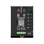
Fig.1 CMM366-4G Panel Drawing
Table 3 Indicator Description
| Icon | Note |
| POWER/ALARM | Green LED Light: Power supply normal indicator Red LED Light: Common alarm indicator |
| RS485(Red) | Normally Extinguish: RS485 disabled Normally Light: Communication fail Blink: Communication normal |
| USB(Red) | Normally Extinguish: USB(Host) disabled Normally Light: Communication fail Blink: Communication normal |
| GPS(Red) | Normally Extinguish: GPS disabled Normally Light: GPS not gained satellite signal Blink: GPS gained satellite signal |
| LINK(Red) | Normally Extinguish: Disabled Normally Light: Communication fail Blink: Communication normal |
| RS232(Red) | Normally Extinguish: RS232 disabled Normally Light: Communication fail Blink: Communication normal |
| GPRS/4G(Red) | Extinguish: CMM366-4G login with server unsuccessfully Light: Login with server successfully Blink: Real-time communication normal |
Lamp test/Rest:
Press this button for 1s, all the LEDs are illuminated; hold and press for 10s, reset the module to default and all the LEDs blink for 3 times.
![]() NOTE: After reset the module, set up the parameters via PC software is recommended. Please operate cautiously.
NOTE: After reset the module, set up the parameters via PC software is recommended. Please operate cautiously.
4.2 GPRS
Connect GPRS antenna to GPRS/4G port.
Antenna: 50Ω/SMA female.
4.3 GPS
GPS enabled, connect GPS antenna to CMM366-4G.
![]() NOTE: GPS antenna needs to be placed to open outdoors, otherwise location information may not accurate or cannot be gained.
NOTE: GPS antenna needs to be placed to open outdoors, otherwise location information may not accurate or cannot be gained.
Antenna: 50Ω/SMA female, active antenna.
 Fig.2 CMM366-4G Antenna Connection
NOTE: GPRS antenna and GPS antenna cannot be connected reversely.
4.4 SIM INSTALLATION
Insert 4G, 3G or 2G SIM card. CMM366-4G will connect to servers via wireless mobile network.
![]() NOTE: All 4G wireless networks are supported. Use standard SIM card (25mmX15mm); if GPS indicator and GPRS indicator blink in the same time, which means SIM card hasn’t been inserted or bad contacts.
NOTE: All 4G wireless networks are supported. Use standard SIM card (25mmX15mm); if GPS indicator and GPRS indicator blink in the same time, which means SIM card hasn’t been inserted or bad contacts.
After removing the head cover, the installation steps are as below:
 Fig.3 SIM Card Installation
4.5 RS485
Receive gen-set data information by RS485 port connecting with gen-set controller RS485 port.
If communication is abnormal, 120Ω terminal resistance is recommonded. If 120Ω resistor is required, please short connect A(+) of RS485 port on CMM366-4G to 120Ω.

Fig.4 RS485 Connection  Fig.5 RS485 Access to 120Ω Resistor
4.6 RS232
Receive genset data information by RS232 port connecting with gen-set controller RS232 port.
 Fig.6 RS232 Connection
4.7 LINK
Receive genset data information by LINK port connecting with gen-set controller LINK port.
 Fig.7 LINK Connection
4.8 USB HOST
Receive genset data information by A-type USB mother port connecting with gen-set controller USB port.
 Fig.8 USB Host Connection
4.9 USB DEVICE
Set up all the parameters and view CMM366-4G ID&Login password by CMM366 USB port connecting with PC USB disk port.
 Fig.9 USB and PC Configuration Connection
4.10 TERMINAL
Table 4 Terminal Descritption
| No. | Function | Cable Size | Note | |
| 1 | B- | 1.0mm2 | Connected with negative of starter battery. | |
| 2 | B+ | 1.0mm2 | Connected with positive of starter battery. 3A fuse is recommended. | |
| 3 | Aux. Input 1 | 1.0mm2 | Active when connect to B-. | |
| 4 | Aux. Input 2 | 1.0mm2 | Active when connect to B-. | |
| 5 | Aux. Output | Normally Open | 1.0mm2 | Normally open outputs, rated lA DC30V. |
| 6 | Common | 1.0mm2 | ||
| 7 | Normally Close | 1.0mm2 | ||
| 8 | RS485 B(-) | 0.5mm2 | If 1200 is used, please short connect A (+) with 1200. | |
| 9 | RS485 A(+) | 0.5mm2 | ||
| 10 | 1200 | 0.5mm2 | ||
| 11 | RS232 RX | 0.5mm2 | RS232 port. | |
| 12 | RS232 TX | 0.5mm2 | ||
| 13 | RS232 GND | 0.5mm2 | ||
PROGRAMMABLE PARAMETERS
5.1 CONTENTS AND SCOPES OF PARAMETERS
Table 5 Parameter Configuration
| No. | Items | Parameters | Defaults | Description |
| Gateway | ||||
| 1 | Site Name | 20 Chinese characters, letters or numbers | ||
| 2 | Server URL | cm.smangen.com.cn 40 characters | ||
| 3 | Server Port | (65535) | 81 | |
| 4 | Security Code | 123456 16 characters | ||
| GPS | ||||
| 1 | GPS Enabled | (0-1) | 1 | 0. Manual Input 1: GPS Location |
| 2 | Longitude | (-180-180)* | 0.000000 | GPS location, altitude |
| 3 | Latitude | (-90-90)* | 0.000000 | |
| 4 | Altitude | (-9999.9-9999.9) | 100.0m | |
| GSM | ||||
| 1 | GSM Enabled | (0-1) | 1 | Cr.Disabiect 1:Enabled |
| 2 | GPRS Password | Reserved | ||
| 3 | SMS Center Number | Reserved | ||
| 4 | PIN Enabled | (0-1) | 0 | 0 Disabled. 1:Enabled |
| 5 | APN | 40 characters | ||
| 6 | SMS Enabled | (0-1) | 0 | tr. Chinese; 1:English |
| 7 | SMS Language Alarm | (0-1) | 0 | |
| 8 | Telephone Number | Max. 20 numbers | Phone number need to be added area code, such as China 8613666666666. | |
| Cloud Server | ||||
| 1 | Auto Gain Communication Port | (0-1) | 1 | 0:Disabled; 1:Enabled |
| 2 | Module ID | (1-254) | 1 | Module ID |
| 3 | Communication Port | (0-4) | 2 | 0: Disabled 1: LINK 2 RS485 3:RS232 4:USB |
| 4 | Baud Rate | (0-2) | 0 | 0: 96001A/s 1: 19200bit/s 2:115200 bit/s |
| 5 | Location Information | (0-1) | 1 | 0: Manual input location info lo 1: Use GPS to gain location |
| 6 | Longitude | (-180.180)* | 0.000000 | Manually set module location and elevation. |
| 7 | Latitude | (-9090)* | 0.000000 | |
| 8 | Altitude | (-9999.9-9999.9) | 100.0 | |
| 9 | Gen-set Model | HGM6110 | See: Form4 | |
| 10 | Module Name | Module Names(20 Chinese characters, letters or numbers) | ||
| 11 | Debugger Name | 20 Chinese characters, letters or numbers | ||
| 12 | Phone Number | 20 Chinese characters, letters or numbers | ||
| 13 | Installation Date | 20 Chinese characters, letters or numbers | ||
| 14 | Historical Upload Interval | (0-3600)s | 0 | History data upload rest. Note: No upload when it is Os |
| 15 | Time Zone | (-12-12) | 8 | Time Zone |
| 16 | Live Data Uploaded Interval | (1-20)s | 5 | Interval time of uploading data. |
| Module Configuration Information | ||||
| 1 | Module Type | (0-5) | 1 | O:AMF module 1: Single-unit self-starting module 2: Single-single parallel module 3: Mains-genset parallel module 4: Mains-bus parallel module 5: Bus-bus parallel module Note: The parameter will auto change according to gen-set type. |
| 2 | Rated Speed | (0-6000)t/min | 1500 | Rated Speed |
| 3 | AC Supply | (0-3) | 0 | a 3P4W; 1: 3P3W: 2: 2P3W. 3: 1P2W |
| 4 | Rated Voltage | (30-30000)V | 230 | Rated Volt |
| 5 | Rated Frequency | (10-600)Hz | 50 | Rated Freq |
| 6 | Rated Current | (5-6000)A | 500 | Rated Current |
| 7 | Rated Power | (0-6000)kW | 276 | Rated Power |
| 8 | Description 1 | Custom Description (20 Chinese characters, letters or numbers) | ||
| 9 | Description 2 | Custom Description (20 Chinese characters, letters or numbers) | ||
| 10 | Description 3 | Custom Description (20 Chinese characters, letters or numbers) | ||
| 11 | Description 4 | Custom Description (20 Chinese characters, letters or numbers) | ||
| 12 | Description 5 | Custom Description (20 Chinese characters, letters or numbers) | ||
| Digital Input | ||||
| Digital Input 1 | ||||
| 1 | Options | (0-9) | 0 | Default: Not used |
| 2 | Activate Type | (0-1) | 0 | 0: Close to activate 1: Open to activate See: Table6 |
| 3 | Delay | (0-20.0) | 0.0 | Action delay |
| Digital Input 2 | ||||
| 3 | Options | (0-9) | 1 | Default: Lamp test |
| 4 | Activate Type | (0-1) | 0 | 0: Close to activate 1: Open to activate See: Table6 |
| 5 | Delay | (0-20.0) | 0.0 | Action delay |
| Digital Output | ||||
| 1 | Options | (0-14) | 0 | Default: Not used See: Table7 |
Table 6 Definition Content of Inputs
| No. | Item | Description |
| 0 | Not Used | Not used. |
| 1 | Lamp Test | All the indicators are illuminated when input is active. |
| 2 | Remote Control InhibitedAccess Alarm Input | Cloud start/stop control is prohibited when input is active. |
| 3 | Fire Alarm Input | Access alarm is uploaded to server when input is active. |
| 4 | Alarm Input | Fire alarm is uploaded to server when input is active. |
| 5 | Reserved | External alarm is uploaded to server when input is active. |
| 6 | Reserved | |
| 7 | Reserved | |
| 8 | Factory Test Mode | It is only used for factory hardware port test when active. |
Table 7 Definition Content of Outputs
| No. | Item | Description |
| 0 | Not used | Description |
| 1 | Digital Input 1 Active | Output port won’t output when this item is selected. |
| 2 | Digital Input 2 Active | Output when auxiliary input 1 is active. |
| 3 | RS485 Communication Failure | Output when auxiliary input 2 is active. |
| 4 | Network Communication Failure | RS485 communication fails. |
| 5 | LINK Communication Failure | Network communication fails. |
| 6 | RS232 Communication Failure | LINK communication fails. |
| 7 | Common Alarm | RS232 communication fails. |
| 8 | Remote Control Output | Output when there is an alarm. |
| 9 | Reserved | Send remote control commands via cloud platform with fixed output delay 20s. |
| 10 | Reserved | |
| 11 | Reserved | |
| 12 | Reserved | |
| 13 | Reserved | |
| 14 | Reserved |
Table 8 Genset Module Type
| Manufachrers | Type | Note |
| SmartGen | ||
| liGM6110/HGM6110CAN | Genset auto-start module | |
| HGM6120/HGM6120CAN | AMF module | |
| HGM7x10 | Genset auto-start module | |
| IIGM7x20 | AMF module | |
| HGM410 | Genset auto-start module | |
| FIGM420 | AMF module | |
| IIGM9120 | AMF module | |
| HGM9210 | Genset auto-start module | |
| HGM9220 | AMF module | |
| HGM9310 | Genset auto-start module | |
| HGM9320 | AMF module | |
| HGM9410 | Genset auto-start module | |
| FiGM9420 | AMF module | |
| HGM9510 | Genset parallel module | |
| HGM9520 | Mains-genset parallel module | |
| HGM9530 | Genset parallel module | |
| HGM9540 | Mains-genset parallel module | |
| HGM9560 | Mains-bus parallel module | |
| FiGM9580 | Bus-bus parallel module | |
| HGM9610 | Genset auto-start module | |
| HGM9620 | AMF module | |
| HGM4010N | Genset auto-start module | |
| HGM4020N | AMF module | |
| HGM1790N | Genset auto-start module | |
| TC1.0 | AMF module | |
| TC2.0 | AMF module | |
| TC3.0 | Genset parallel module | |
| ALC708 | Genset auto-start module | |
| ZX9320 | AMF module | |
| HSC943 | Genset auto-start module | |
| DeepSea | DSE7110MKII | Genset auto-start module |
| DSE7120MKII | AMF module | |
| DSE7210 | Genset auto-start module | |
| DSE7220 | AMF module | |
| DSE7310 | Genset auto-start module | |
| DSE7320 | AMF module | |
| DSE7410 | Genset auto-start module | |
| DSE7420 | AMF module | |
| DSE7450 | Genset auto-start module | |
| DSE8610 | Genset parallel module | |
| DSE8620 | Mains-genset parallel module | |
| ComAp | MRS10 Ⅱ | Genset auto-start module |
| MRS16 Ⅱ | Genset auto-start module | |
| AMF25 Ⅱ | AMF module | |
| IGNT | Genset parallel module | |
| MINT | Genset parallel module | |
| SPTM | Mains-genset parallel module | |
| MC-NT | Mains-bus parallel module | |
| Harsen | GU620A | Genset auto-start module |
| GU621A | AMF module | |
| GU630A | Genset auto-start module | |
| GU631A | AMF module | |
| GU620A-00 | Genset auto-start module | |
| GU621A-00 | AMF module | |
| GU630A-00 | Genset auto-start module | |
| GU631A-00 | AMF module | |
| GU320A | Genset auto-start module | |
| GU320B | Genset auto-start module |
5.2 PC CONFIGURATION INTERFACE
The USB port of CMM366-4G communication module connects PC port to configure the parameters.
 Fig.10 Gateway Configuration
 Fig.11 Cloud Server Configuration
 Fig.12 Module Monitoring Interface
SMS FUNCTION AND REMOTE CONTROL
6.1 SMS ALARM
When controller detects alarm, it will send short message to phone automatically.
![]() NOTE: SMS alarm function only suit for SmartGen HGM7000 series and HGM9000 series controllers.
NOTE: SMS alarm function only suit for SmartGen HGM7000 series and HGM9000 series controllers.
![]() NOTE: All alarms about shutdown, trip and stop and trip alarms will be sent to the pre-set phone. Warnings are sent to the phone according to the pre-set.
NOTE: All alarms about shutdown, trip and stop and trip alarms will be sent to the pre-set phone. Warnings are sent to the phone according to the pre-set.
6.2 SMS CONTROL
Users send order message to the module, then controller will make actions according to this SMS order and pass back corresponding operations information. Controllers only execute the orders by pre-set.
Table 9 SMS Orders List
| No. | SMS Orders | Pass Back Information | Description | ||
| 1 | SMS GENSET | GENSET ALARM | When gen-set is stopping alarm | status of gen-set | |
| SYSTEMIN STOP MODE GENSET AT REST | At rest status in stop mode | ||||
| SYSTEM IN MANUAL MODE GENSET AT REST | At rest status in manual mode | ||||
| SYSTEM IN TEST MODE GENSET AT REST | At rest status in test mode | ||||
| SYSTEM IN AUTO MODE GENSET AT REST | At rest status in auto mode | ||||
| SYSTEMIN STOP MODE GENSET IS RUNNING | Running status in stop mode | ||||
| SYSTEMIN MANUAL MODE GENSET IS RUNNING | Running status in manual mode | ||||
| SYSTEMIN TEST MODE GENSET IS RUNNING | Running status in test mode | ||||
| SYSTEMIN AUTO MODE GENSET IS RUNNING | Running status in auto mode | ||||
| 2 | SMS START | GENSET ALARM | Generator is shutdown alarm or trip alarm | Start gen-set | |
| STOP MODE NOT START | Cannot start in stop mode | ||||
| SMS START OK | Start in manual/test mode | ||||
| AUTO MODE NOT START | Cannot start in auto mode | ||||
| 3 | SMS STOP MODE | SMS STOP OK | Set as stop mode | ||
| 4 | SMS MANUAL MODE | SMS MANUAL MODE OK | Set as manual mode | ||
| 5 | SMS TEST MODE | SMS TEST MODE OK | Set as test mode | ||
| 6 | SMS AUTO MODE | SMS AUTO MODE OK | Set as auto mode | ||
| 7 | SMS DETAIL | Pass back information can be set via controller software. | Gets details information of gen-set | ||
![]() NOTE: When sending orders, users need to follow SMS orders in above form and all the letters must be capital.
NOTE: When sending orders, users need to follow SMS orders in above form and all the letters must be capital.
![]() NOTE: Pass back information from SMS DETAIL including: working mode, mains voltage, generator voltage, load current, mains frequency, generator frequency, active power, apparent power, power factor, battery voltage, D+ voltage, water temperature, oil pressure, oil level, engine speed, total running time, gen-set status, and alarm status.
NOTE: Pass back information from SMS DETAIL including: working mode, mains voltage, generator voltage, load current, mains frequency, generator frequency, active power, apparent power, power factor, battery voltage, D+ voltage, water temperature, oil pressure, oil level, engine speed, total running time, gen-set status, and alarm status.
SYSTEM DIAGRAM
One CMM366-4G module connects with one gen-set monitor module. It can be connected via RS485 port, LINK port, RS232 port or USB port.
 Fig.13 CMM366 System Diagram
CASE DIMENSION AND INSTALLATION
2 ways for installation: 35mm guide rail in box or screw (M4) installation as below:
 Fig.14 CMM366-4G Case Dimension
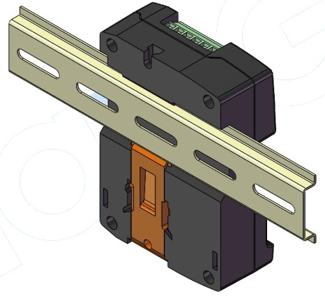 Fig.15 CMM366-4G Guide Rail Installation
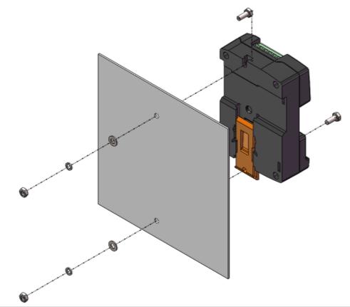 Fig.16 CMM366-4G Screw Installation
FAULT FINDING
Table 10 Fault Finding
| Symptoms | Possible Solutions | |
| Controller No Response with Power |
Check power voltage: Check controller connection wirings. |
|
| GPRS/4G Indicator Not Light | Check SIM card is inserted or not; Check GPRS antenna is connected or not. |
|
| GPS Not Gained Location | Check GPS parameters are enabled or not Check GPS antenna is connected or not and placed outdoor or not. |
|
| RS485 Communication Abnormal | Check connections: Check RS485 port is enabled or not; Check settings of gen-set ID and baud rate are correct or not. Check RS485’s connect ions of A and B is reverse connect or not. |
|
| RS232 Communication Abnormal | Check connections; Check RS232 port is enabled or not; Check settings of gen-set ID and baud rate are correct or not. |
|
| LINK Communication Abnormal | Check connections; Check LINK port is enabled or not: Check settings of gen-set ID and baud rate are correct or not. |
|
![]()
Documents / Resources
 |
SmartGen CMM366-4G Cloud Monitoring Communication Module [pdf] User Manual CMM366-4G Cloud Monitoring Communication Module, CMM366-4G, Cloud Monitoring Communication Module, Monitoring Communication Module, Communication Module, Module |