
SILICON LABS AN1444 RCP 2.4 GHz Radio Board User Guide

This document provides detailed instructions for setting up the SiWT917 Single Band Wi-Fi + Bluetooth Low Energy Development Kit using a Raspberry Pi board to enable Wi-Fi support. It includes steps for flashing the RPI4 OS image and configuring the SiWT917 in Wi-Fi STA mode to connect to a router.
KEY POINTS
- Setup Requirements
- Flashing RPI4 OS
- Wi-Fi STA bring-up
1. Introduction
This guide provides detailed and comprehensive instructions for setting up the SiWT917 Single Band Wi-Fi + Bluetooth Low Energy Development Kit using a Raspberry Pi board.
The primary goal is to enable Wi-Fi functionality on the development kit. The guide includes step-by-step procedures for flashing the RPI4 OS image onto the Raspberry Pi, ensuring that the operating system is correctly installed and ready for use.
Additionally, it covers the configuration of the SiWT917 in Wi-Fi Station (STA) mode, which allows the device to connect to a Wi-Fi router. This setup enables seamless wireless communication and enhances the overall functionality of the development kit.
2. Prerequisites
Following are the details for the prerequisites required for both hardware and software.
2.1 Hardware Requirements
Following are the details for hardware requirements.

Note: For more information, refer to Getting Started Guide.
2.2 Software Requirements
Following are the details for software requirements.

3. Functional Description SiWT917 on Raspberry Pi4
SiWT917 enables Raspberry Pi with Wi-Fi capability. We will enable W-Fi support on the Raspberry Pi 4 board using the SiWT917 Single band Wi-Fi + Bluetooth low energy using the SDIO interface.
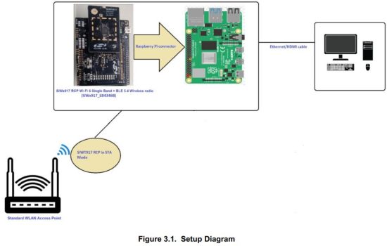
In the above figure the user needs to connect the SiWT917 RCP module to a Raspberry Pi 4 running Raspberry Pi 4 OS through the Raspberry Pi connector (40 PIN header). The Raspberry Pi should have a kernel version installed between 3.18 to 6.1. To evaluate STA mode, an external standard wlan access point is needed.
3.1 Advantages
Wi-Fi capability on target platform, which can be used to use for network connectivity.
3.2 Use Cases
Enabling Wi-Fi support on the target platform will be used as STA Mode.
4. Usage Guidelines
4.1 Configuration Parameters for Driver Package
- Download the RPI OS image from the below link : SiWx917_RCP_image_with_RPI4.img.
- Download the RPI Imager tool: RPI-Imager.
- Connect the empty SD card (atleast 32 GB size) to the Windows machine via the SD memory card slot/SD card reader/SD card adapter.
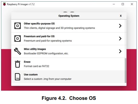
- Launch the RPI imager. It will pop up the window as shown below.

- Choose the OS and select Use custom icon.
- Select the RPI-4B image from the directory where the image is downloaded. Select the Choose Storage button and it will pop up the SD card partition.

- Now click on the Write button.
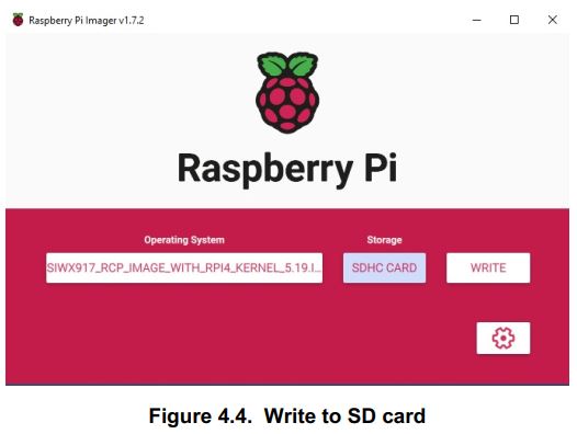
- It will prompt for confirmation. Click, Yes.

- The image will start flashing onto the selected SD card partition. Wait until the card flashing is done.

- Once the flashing is complete. A window will pop up showing that the write was successful.

- Remove the SD card from the SD card reader and insert it on RPI-4B Pi.
4.2 Connecting SiWT917 to Raspberry Pi 4 and Accessing Console
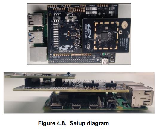
Connect the SiWT917_BRD8045B and radioboard to the 40 pin header of Raspberry Pi 4, as shown below.
- Connect the 5V power adapter/power up through USB to the Type C USB port of the RPi4 board.
- Connect the ethernet cable from the ethernet port on RPi to the Windows/Linux PC.
- Static IP is assigned to RPI and the IP of the RPi4 is 192.168.30.10
- Give the IP address for the Linux/Windows PC in the same subnet of 192.168.30.X For example:
• If Linux PC: ifconfig eth0 192.168.30.15
• If Windows PC: Configure the network settings with 192.168.30.15 - Check the ping to RPi4 board IP 192.168.30.10(Exp: ping 192.168.30.10).
- Log in to the RPi4 Console using ssh/putty (By default, the IP address of the RPi4 is 192.168.30.10). or
- User can access the RPi4 using the HDMI connector cable connected to the HDMI supported monitor.
- After powering up, it will ask for username and password.
• Username: pi
• Password: test123
4.3 Steps to Bring up in STA Mode
- Download the si91x-rcp-driver
- Place the driver in any local path of the RPi4 home directory.
Example: esystem_path:• : cd lhome/pi/
Note: “«system_pathY’ is the location where the user has downloaded/placed the SiWT917 driver in the system. - Unzip the driver using the following command.
# unzip SiWT917.x.x.x.x.zip - Now user needs to enter super user mode by giving the following command and providing the correct username and password.
# sudo su
The subsection below provides the steps to configure Wi-Fi STA using startup script or manual commands. User can choose any method.
4.3.1 Using Startup Scripts
User can use the script at path “<system_path>/SiWT917.x.x.x.x/release/” to run Wi-Fi concurrent mode.
Example: ./start_SiWT917.sh STA
For more details about the startup script file, refer to the Startup Script section of SiWT917 RCP Developer’s Guide.
4.3.2 Using Manual Steps


Note: In this test case, the wireless interface created after loading of a driver is wlan0. The interface name may vary across the systems.


5. Summary/Conclusion
This document provided detailed instructions for the compilation, installation, and bring up of SiWT917 RCP module in STA mode using a Raspberry Pi 4 board.
6. Appendix A: Terminology
Common acronyms and abbreviations used in this document:
- AP – Access Point.
- STA – Station.
- TAP – Third party WLAN Access Point.
- SiWT917-STA – Station interface that is created for SiWT917 RCP after loading the driver.
- SiWT917-AP – Access Point interface that is created for SiWT917 RCP after loading the driver.
- Refer to SiWT917 RCP Developers Guide and Getting Started Guide.
- Refer to the following link for the purchase of Raspberry Pi board: https://www.raspberrypi.com/products/.
8. Appendix C: Troubleshooting
- Ensure that dev_oper_mode is configured as per the mode selected. (for STA mode: dev_oper_mode = 1).
- If unknown symbols are observed in the dmesg logs, run the commands below and reload the driver.
- modprobe mac80211
- modprobe bluetooth
- modprobe rfcomm
9. Revision History
Revision 1.0
January 2025
- Initial release.


Disclaimer
Silicon Labs intends to provide customers with the latest, accurate, and in-depth documentation of all peripherals and modules available for system and software implementers using or intending to use the Silicon Labs products. Characterization data, available modules and peripherals, memory sizes and memory addresses refer to each specific device, and “Typical” parameters provided can and do vary in different applications. Application examples described herein are for illustrative purposes only. Silicon Labs reserves the right to make changes without further notice to the product information, specifications, and descriptions herein, and does not give warranties as to the accuracy or completeness of the included information. Without prior notification, Silicon Labs may update product firmware during the manufacturing process for security or reliability reasons. Such changes will not alter the specifications or the performance of the product. Silicon Labs shall have no liability for the consequences of use of the information
supplied in this document. This document does not imply or expressly grant any license to design or fabricate any integrated circuits. The products are not designed or authorized to be used within any FDA Class III devices, applications for which FDA premarket approval is required or Life Support Systems without the specific written consent
of Silicon Labs. A “Life Support System” is any product or system intended to support or sustain life and/or health, which, if it fails, can be reasonably expected to result in significant personal injury or death. Silicon Labs products are not designed or authorized for military applications. Silicon Labs products shall under no circumstances be used in weapons of mass destruction including (but not limited to) nuclear, biological or chemical weapons, or missiles capable of delivering such weapons. Silicon Labs disclaims all express and implied warranties and shall not be responsible or liable for any injuries or damages related to use of a Silicon Labs product in such unauthorized applications.
Trademark Information
Silicon Laboratories Inc.®, Silicon Laboratories®, Silicon Labs®, SiLabs® and the Silicon Labs logo®, Bluegiga®, Bluegiga Logo®, EFM®, EFM32®, EFR, Ember®, Energy Micro, Energy Micro logo and combinations thereof, “the world’s most energy friendly microcontrollers”, Redpine Signals®, WiSeConnect , n-Link, EZLink®, EZRadio®, EZRadioPRO®, Gecko®, Gecko OS, Gecko OS Studio, Precision32®, Simplicity Studio®, Telegesis, the Telegesis Logo®, USBXpress® , Zentri, the Zentri logo and Zentri DMS, Z-Wave®, and others are trademarks or registered trademarks of Silicon Labs. ARM, CORTEX, Cortex-M3 and THUMB are trademarks or registered trademarks of ARM Holdings. Keil is a registered trademark of ARM Limited. Wi-Fi is a registered trademark of the Wi-Fi Alliance. All other products or brand names mentioned herein are trademarks of their respective holders.
 Silicon Laboratories Inc.
400 West Cesar Chavez
Austin, TX 78701
USA
www.silabs.com
Read More About This Manual & Download PDF:
Documents / Resources
 |
SILICON LABS AN1444 RCP 2.4 GHz Radio Board [pdf] User Guide AN1444, AN1444 RCP 2.4 GHz Radio Board, RCP 2.4 GHz Radio Board, Radio Board, Board |


