![]() SHN900A Series
SHN900A Series
Vector Network
Analyzer
Data Sheet
EN01A SIGLENT TECHNOLOGIES CO.,LTD
General Description
The SIGLENT SHN900A series of Vector Network Analyzers have a frequency range of 30 kHz to 26.5 GHz, which support 2-port scattering parameter, differential-parameter, and time-domain parameter measurements. The SHN900A series of VNAs are effective instrumentation for determining the Q-factor, bandwidth, and insertion loss of a filter, They feature impedance conversion, movement of measurement plane, limit testing, ripple test, fixture simulation, and adapter removal/insertion adjustments. The VNAs have five sweep types: Linear-Frequency mode, Log-Frequency mode, Power-Sweep mode, CW-Time mode, and Segment-Sweep mode. The SHN900A series VNAs also support scattering-parameter correction of SOLT, SOLR, TRL, Response, and Enhanced Response for increased flexibility in R&D and manufacturing applications.
Key Features
![]() Frequency range: 30 kHz – 26.5 GHz
Frequency range: 30 kHz – 26.5 GHz
![]() Frequency resolution: 1 Hz
Frequency resolution: 1 Hz
![]() Level resolution: 0.01 dB
Level resolution: 0.01 dB
![]() Range of IFBW: 10 Hz~3 MHz
Range of IFBW: 10 Hz~3 MHz
![]() Setting range of output level:
Setting range of output level:
![]() -45 dBm ~ +10 dBm
-45 dBm ~ +10 dBm
![]() Dynamic range: 110 dB(Typ.)
Dynamic range: 110 dB(Typ.)
![]() Types of calibration: Response calibration, Enhanced Response calibration, Full-one port calibration, Full-two port calibration, TRL calibration
Types of calibration: Response calibration, Enhanced Response calibration, Full-one port calibration, Full-two port calibration, TRL calibration
![]() Types of measurement: Scattering-parameter measurement, differential-parameter measurement, receiver measurement, time-domain parameter analysis, limit test, ripple test, impedance conversion, fixture simulation, adapter removal/insertion, spectrum analysis frequency offset, scalar mixer measurement, pulse measurement
Types of measurement: Scattering-parameter measurement, differential-parameter measurement, receiver measurement, time-domain parameter analysis, limit test, ripple test, impedance conversion, fixture simulation, adapter removal/insertion, spectrum analysis frequency offset, scalar mixer measurement, pulse measurement
![]() Internal Bias-Tee connections
Internal Bias-Tee connections
![]() Support GPS, Time and Location Information Saving
Support GPS, Time and Location Information Saving
![]() Interface: LAN, USB Device, USB Host (USB-GPIB)
Interface: LAN, USB Device, USB Host (USB-GPIB)
![]() Remote control: SCPI/ Labview/ IVI based on USB-TMC / VXI-11 / Socket /Telnet / WebServer
Remote control: SCPI/ Labview/ IVI based on USB-TMC / VXI-11 / Socket /Telnet / WebServer
![]() 8.4-inch touch screen, Mouse, Keyboard
8.4-inch touch screen, Mouse, Keyboard
Models and Key Specifications
| Model | SHN914A | SHN920A | SHN926A |
| Frequency range | 30kHz-14GHz | 30kHz-20GHz | 30kHz-26.5GHz |
| Ports | 2 | ||
| Frequency resolution | 1 Hz | ||
| Level resolution | 0.01 dB | ||
| Range of IFBW | 10 Hz~3 MHz | ||
| Setting range of output level | -45 dBm ~ +10 dBm | ||
| Dynamic range | 110 dB(Typ.) | ||
| Types of calibration | Response calibration, Enhanced Response calibration, Full-one port calibration, Full-two port calibration, TRL calibration | ||
| Types of measurement | Scattering-parameter measurement, differential-parameter measurement, receiver measurement, time-domain parameter analysis, limit test, ripple test, impedance conversion, fixture simulation, adapter removal/insertion, enhanced time-domain parameter analysis (TDR), spectrum analysis, frequency offset, scalar mixer measurement, pulse measurement | ||
| Bias-Tees | Support | ||
| Interface | LAN, USB Device, USB Host(USB-GPIB) | ||
| Remote control | SCPI/ Labview/ IVI based on USB-TMC/ VXI-11/ Socket/ Telnet/ WebServer | ||
| Display | 8.4-inch touch screen | ||
| GPS | Support | ||
Design Features
Multi-window display: 
Multi-format display: 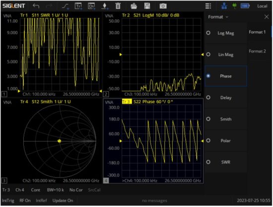
Display and compare memory and current data: 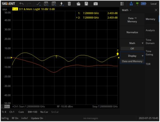
Display data hold: 
Impedance conversion: 
Equation Editor: 
Port Extensions: 
Embedding and De-Embedding: 
CAT 
Time-Domain analysis 
Enhanced Time-Domain analysis(TDR) 
Spectrum analysis 
Definitions
Specifications are valid under the following conditions: The instrument is within the calibration period, has been stored between 0 and 40℃ for at least 2 hours before use, and has been powered on and warmed up for at least 90 minutes. The specifications include the measurement uncertainty unless otherwise noted.
Specifications: All products are guaranteed to meet published specifications at room temperature (approximately 25℃), unless otherwise noted.
Typical: Performance deemed typical implies that 80 percent of the measurement results will meet the typical published performance with a 95th percentile confidence level at room temperature (approximately 25℃). Typical performance is not warranted and does not include measurement uncertainty.
Nominal: This value indicates the expected mean or average performance, or an attribute whose performance is by design, such as the 50 Ohm connector.
Specifications
Dynamic range
| Frequency range | IFBW | Specification(dB) | Typical(dB) |
| 30 kHz – 1 MHz | 10Hz | 90 | 100 |
| 1 MHz – 6 GHz | 100 | 110 | |
| 6 GHz – 8 GHz | 80 | 110 | |
| 8 GHz – 14 GHz | 100 | 105 | |
| 14 GHz – 24 GHz | 100 | 105 | |
| 24 GHz – 26.5 GHz | 95 | 100 |
Corrected system performance with calibration kit
User correction: On, system correction: On; Corrected system performance with Keysight 85052D 3.5mm calibration kit, isolation calibration performed.IFBW is 10 Hz, no averaging applied to data, and environmental temperature is 25℃ (± 5℃), with < 1℃ deviation from calibration temperature.
| Specification (dB) | 30kHz-3 GHz | 3GHz-6 GHz | 6GHz-14 GHz | 9 GHz-20GHz | 14GHz-26.5GHz |
| Directivity | 41 | 39 | 37 | 37 | 37 |
| Source match | 36 | 30 | 29 | 29 | 29 |
| Load match | 41 | 37 | 35 | 35 | 35 |
| Reflect tracking | ±0.004 | ±0.003 | ±0.004 | ±0.004 | ±0.004 |
| Transmission tracking | ±0.06 | ±0.09 | ±0.11 | ±0.11 | ±0.11 |
Reflection uncertainty (Specification, Power: -10 dBm, IFBW:10 Hz):

Transmission uncertainty (Specification, Power: -10 dBm, IFBW:10 Hz):

Uncorrected system performance
User correction: Off, system correction: On; IFBW is 10 Hz, no averaging applied to data.
| Specification (dB) | 30kHz – 300kHz | 300kHz – 1 GHz | 1GHz-6 GHz | 6 GHz-26.5GHz |
| Directivity | 15 | 15 | 16 | 16 |
| Source match | 11 | 16 | 16 | 18 |
| Load match | 5 | 5 | 10 | 7 |
| Reflect tracking | ±1.4 | ±1.4 | ±1 | ±1 |
| Transmission tracking | ±1.4 | ±1.4 | ±1 | ±1 |
Test port output (Source)
![]() Test port output frequency
Test port output frequency
| Description | Specification |
| Frequency range | |
| SHN914A | 30 kHz to 14 GHz |
| SHN920A | 30 kHz to 20 GHz |
| SHN926A | 30 kHz to 26.5 GHz |
| Frequency resolution | 1 Hz |
| CW accuracy | |
| Standard | ± 1.0 ppm (23 ± 3℃) |
| Source stability | |
| Standard | ± 1.0 ppm (0 to 40℃) ± 0.5 ppm/year, ± 3.0 ppm/20 year |
![]() Test port output power
Test port output power
| Description | Specification |
| Preset power | -10 dBm |
| Level accuracy | ±1.5 dB@-10 dBm 30kHz ~ 20GHz ±2.5 dB@-10 dBm 20GHz ~ 26.5GHz |
| Level linearity | |
| 30 kHz – 100 kHz | ±1 dB (-20 dBm to -11 dBm) |
| 100 kHz – 25 MHz | ±1 dB (-20 dBm to 0 dBm) |
| 25 MHz – 20 GHz | ±1 dB (-20 dBm to -1 dBm) |
| 20 GHz – 26.5 GHz | ±2 dB (-20 dBm to -8 dBm) |
| Range | |
| 30 kHz – 100 kHz | -45 dBm to -11 dBm |
| 100 kHz – 25 MHz | -45 dBm to -5 dBm |
| 25 MHz – 20 GHz | -45 dBm to -1 dBm |
| 20 GHz – 26.5 GHz | -45 dBm to -8 dBm |
| Sweep range | |
| 30 kHz – 100 kHz | -45 dBm to -11 dBm |
| 100 kHz – 25 MHz | -45 dBm to -5 dBm |
| 25 MHz – 20 GHz | -45 dBm to -1 dBm |
| 20 GHz – 26.5 GHz | -45 dBm to -8 dBm |
| Max leveled power | |
| 30 kHz – 100 kHz | -11 dBm (Typ.) |
| 100 kHz – 25 MHz | -4 dBm (Typ.) |
| 25 MHz – 100 MHz | 0 dBm (Typ.) |
| 100 MHz – 6 GHz | 2 dBm (Typ.) |
| 6 GHz – 8 GHz | 0 dBm (Typ.) |
| 8 GHz – 14 GHz | 2 dBm (Typ.) |
| 14GHz – 20 GHz | 0 dBm (Typ.) |
| 20 GHz – 26.5 GHz | -6 dBm (Typ.) |
| Level resolution | 0.05 dB |
![]() Test port output signal purity
Test port output signal purity
| Description | Specification |
| 2nd or 3rd harmonics (0 dBm) | |
| 100 kHz to 25 MHz | < -10 dBc |
| 25 MHz to 8 GHz | < -10 dBc |
| 9 GHz to 26.5 GHz | < -10 dBc |
| Non-harmonic spurious (0 dBm) | < -20 dBc |
Test port input
![]() Test port input levels
Test port input levels
| Description | Specification | Typical |
| Max input level | ||
| 30 kHz-14 GHz | +10 dBm | |
| 14 GHz-26.5 GHz | +10 dBm | |
| Damage input level | ||
| 30 kHz-26.5 GHz | +27 dBm (RF) or 35 V (DC) | |
| Precision | ||
| 30 kHz -1 GHz | ±1.5 dB@-15 dBm | ±0.2 dB@-15 dBm |
| 1 GHz – 20 GHz | ±2.0 dB@-15 dBm | ±0.2 dB@-15 dBm |
| 20 GHz – 26.5 GHz | ±2.5 dB@-15 dBm | ±0.5 dB@-15 dBm |
| Crosstalk | ||
| 30 kHz -100 kHz | -95 dB | -105 dB |
| 100 kHz – 6 GHz | -75 dB | -120 dB |
| 6 GHz – 9 GHz | -80 dB | -105 dB |
| 9 GHz – 20 GHz | -95 dB | -105 dB |
| 20 GHz – 26.5 GHz | -60 dB | -70 dB |
| Noise floor | ||
| 30 kHz – 50 kHz | -70 dBm/Hz | -80 dBm/Hz |
| 50 kHz – 200 kHz | -90 dBm/Hz | -110 dBm/Hz |
| 200 kHz – 6.2 GHz | -100 dBm/Hz | -120 dBm/Hz |
| 6.2 GHz – 9 GHz | -90 dBm/Hz | -100 dBm/Hz |
| 9 GHz – 22 GHz | -100 dBm/Hz | -115 dBm/Hz |
| 22 GHz – 26.5 GHz | -80 dBm/Hz | -110 dBm/Hz |
| Compression level(+10 dBm) | ||
| Magnitude | ||
| 30 kHz- 26.5 GHz | 1 dB | |
| Phase | ||
| 30 kHz- 26.5 GHz | 5 deg | |
![]() Trace noise
Trace noise
| Description | Specification | Typical |
| Note:Setting max output power | ||
| Transmission trace noise magnitude | ||
| 30 kHz- 50 kHz (IFBW=30 Hz) | 0.003 dB rms | 0.0015 dB rms |
| 50 kHz- 1 MHz (IFBW=30 Hz) | 0.003 dB rms | 0.0015 dB rms |
| 1 MHz- 9 GHz (IFBW=10 kHz) | 0.003 dB rms | 0.0015 dB rms |
| 9 GHz-14 GHz (IFBW=10 kHz) | 0.005 dB rms | 0.0025 dB rms |
| 14GHz-26.5 GHz (IFBW=10 kHz) | 0.005 dB rms | 0.0025 dB rms |
| Reflection trace noise magnitude | ||
| 30 kHz- 50 kHz (IFBW=30 Hz) | 0.003 dB rms | 0.0005 dB rms |
| 50 kHz- 1 MHz (IFBW=30 Hz) | 0.003 dB rms | 0.0007 dB rms |
| 1 MHz- 9 GHz (IFBW=10 kHz) | 0.003 dB rms | 0.0015 dB rms |
| 9 GHz-14 GHz (IFBW=10 kHz) | 0.004 dB rms | 0.002 dB rms |
| 14GHz-26.5 GHz (IFBW=10 kHz) | 0.004 dB rms | 0.002 dB rms |
| Transmission trace noise phase | ||
| 30 kHz- 50 kHz (IFBW=30 Hz) | 0.03 deg rms | 0.015 deg rms |
| 50 kHz- 1 MHz (IFBW=30 Hz) | 0.03 deg rms | 0.015 deg rms |
| 1 MHz- 9 GHz (IFBW=10 kHz) | 0.04 deg rms | 0.004 deg rms |
| 9 GHz-14 GHz (IFBW=10 kHz) | 0.04 deg rms | 0.004 deg rms |
| 14GHz-26.5 GHz (IFBW=10 kHz) | 0.06 deg rms | 0.006 deg rms |
| Reflection trace noise phase | ||
| 30 kHz- 50 kHz (IFBW=30 Hz) | 0.03 deg rms | 0.015 deg rms |
| 50 kHz- 1 MHz (IFBW=30 Hz) | 0.03 deg rms | 0.015 deg rms |
| 1 MHz- 9 GHz (IFBW=10 kHz) | 0.04 deg rms | 0.004 deg rms |
| 9 GHz-14 GHz (IFBW=10 kHz) | 0.04 deg rms | 0.004 deg rms |
| 14GHz-26.5 GHz (IFBW=10 kHz) | 0.06 deg rms | 0.006deg rms |
![]() Stability
Stability
| Description | Specification | Typical |
| Magnitude | ||
| 30 kHz- 9 GHz | ± 0.01 dB/°C | |
| 9 GHz- 26.5 GHz | ± 0.05 dB/°C | |
| Phase | ||
| 30 kHz- 9 GHz | ± 0.1 deg/°C | |
| 9 GHz- 26.5 GHz | ± 0.3 deg/°C | |
![]() Dynamic accuracy
Dynamic accuracy
| Description | Specification |
| Relative to -10 dBm input power | |
| Magnitude | |
| -10 dBm | ± 0.5 dB |
| -30 dBm | ± 0.5 dB |
| -55 dBm | ± 2.5 dB |
| Phase | |
| -10 dBm | ± 4.5 deg |
| -30 dBm | ± 5 deg |
| -55 dBm | ± 16.5 deg |
SA Mode
| Description | Specification | Typical |
| Power Range | -70dBm – +15dBm | |
| Noise Floor | 110 dBm/Hz – 130dBm/Hz | 130dBm/Hz |
| Phase Noise | ≤ -98dBc/Hz (1GHz@100kHz) | |
| Max Input Level Without Damaged | 27dBm | |
| Residual Response | ≤ -80dBm | -100dBm |
CAT Mode
| Description | Specification |
| DTF | Range: Velocity Factor ×Light Velocity×(Points Number- 1)/BW×2 Resolution: Range/(Points Number- 1) |
| Return Loss Range(dB) | -6k dB – +6k dB |
| VSWR Resolution | 1mdB – 1k dB |
| VSWR Range | 1.001 – 1G |
| VSWR Resolution | 0.001 |
Sweep time
| Start frequency: 30 kHz, Stop frequency: 14 GHz; IFBW: 500 kHz | ||||
| Points | 201 | 401 | 1601 | 6401 |
| 2-port cal | 28 ms | 28 ms | 75 ms | 300 ms |
| Start frequency: 30 kHz, Stop frequency: 14 GHz; IFBW: 100 kHz. | ||||
| Points | 201 | 401 | 1601 | 6401 |
| 2-port cal | 30 ms | 30 ms | 85 ms | 340 ms |
| Start frequency: 30 kHz, Stop frequency: 14 GHz; IFBW: 10 kHz. | ||||
| Points | 201 | 401 | 1601 | 6401 |
| 2-port cal | 60 ms | 70 ms | 350 ms | 1400 ms |
| Start frequency: 30 kHz, Stop frequency: 14 GHz; IFBW: 1 kHz. | ||||
| Points | 201 | 401 | 1601 | 6401 |
| 2-port cal | 300 ms | 500 ms | 2500 ms | 10000 ms |
| Start frequency: 30 kHz, Stop frequency: 26.5 GHz; IFBW: 500 kHz. | ||||
| Points | 201 | 401 | 1601 | 6401 |
| 2-port cal | 28 ms | 28 ms | 75 ms | 300 ms |
| Start frequency: 30 kHz, Stop frequency: 26.5 GHz; IFBW: 100 kHz. | ||||
| Points | 201 | 401 | 1601 | 6401 |
| 2-port cal | 30 ms | 30 ms | 85 ms | 340 ms |
| Start frequency: 30 kHz, Stop frequency: 26.5 GHz; IFBW: 10 kHz. | ||||
| Points | 201 | 401 | 1601 | 6401 |
| 2-port cal | 60 ms | 70 ms | 350 ms | 1400 ms |
| Start frequency: 30 kHz, Stop frequency: 26.5 GHz; IFBW: 1 kHz. | ||||
| Points | 201 | 401 | 1601 | 6401 |
| 2-port cal | 300 ms | 500 ms | 2500 ms | 10000 ms |
General information
| Description | Characteristics |
| Operating environment | |
| Temperature | 0 to 40 ℃ |
| Humidity | 85%: 40 ℃, 24 hours |
| Altitude | 0 to 3000 m |
| Non-operating storage environment | |
| Temperature | -20 ℃ to 70 ℃ |
| Humidity | 85%: 65 ℃, 24 hours |
| Altitude | 0 to 15000 m |
| Size | W×H×D=310 mm × 215 mm × 78.5 mm |
| Weight | 3.2 kg |
| EMC | |
| Conducted disturbance: CISPR 11/EN 55011 | CLASS A group 1, 150 kHz – 30 MHz |
| Radiated disturbance: CISPR 11/EN 55011 | CLASS A group 1, 30 MHz -1 GHz |
| Electrostatic discharge(ESD): IEC61000-4-2/EN61000-4-2 | 4.0 kV (contact), 8.0 kV (air) |
| Radio-frequency electromagnetic field Immunity: IEC 61000-4-3/EN 61000-4-3 | 10 V/m (80 MHz to 1 GHz); 3 V/m (1.4 GHz to 2 GHz); 1 V/m (2.0 GHz to 2.7 GHz) |
| Electrical fast transients (EFT): IEC 61000-4-4/EN 61000-4-4 | 2 kV (AC power ports) |
| Surges: IEC 61000-4-5/EN 61000-4-5 | 1 kV (Line to line) ; 2 kV (Line to ground) |
| Radio-frequency continuous conducted Immunity: IEC 61000-4-6/EN 61000-4-6 | 3 V, 0.15-80 MHz |
| Voltage dips and interruptions: IEC 61000-4-11/EN 61000-4-11 | Voltage dips: 0% UT during 1 cycle; 40% UT during 10/12 cycles; 70% UT during 25/30 cycles; Voltage interruptions: 0% UT during 250 cycles |
| Safety | |
| UL 61010-1:2012/R: 2018-11; CAN/CSA-C22.2 No. 61010-1:2012/A1:2018-11. UL 61010-2-030:2018; CAN/CSA-C22.2 No. 61010-2-030:2018. | |
Panel information
| Top Panel | |
| RF connectors | 3.5mm NMD (male), 50Ω |
| USB Host | USB-A 2.0 |
| USB Device | USB-C 2.0 |
| LAN | LAN (VXI11), 10/100 Base, RJ-45 |
| GPS Antenna | SMA Female, 3.3V, 50Ω |
| Bias Out | SMB Female, 12V-32V, step 0.1V |
| External Trigger Input | 1 kΩ, 5V TTL, BNC Female |
| 10M Reference Input | 10 MHz, -5 dBm~+10 dBm, BNC Female, 50Ω |
| Remote control | |
| Hardware connectors | LAN, USB-TMC, GPIB (USB-GPIB adaptor) |
| Remote control interfaces | SCPI/ Labview/ IVI based on USB-TMC/ VXI-11/ GPIB/ Socket/Telnet NI-MAX Web Browser (HTML 5 Supported) |
Ordering Information
| Items | Description | Order number |
| Products | 2 ports, 14G Vector Network Analyzer | SHN914A |
| 2 ports, 20G Vector Network Analyzer | SHN920A | |
| 2 ports, 26.5G Vector Network Analyzer | SHN926A | |
| standard fittings | Quick Start, USB Type C Line, Rechargeable lithium battery, AC-DC adapter, Portable bag | |
| TDA Option | Time Domain Analysis | SHN900-TDA |
| TDR Option | Enhanced Time Domain Analysis | SHN900-TDR |
| SA Option | Spectrum analysis | SHN900-SA |
| 3.5mm, Male, 50Ω Calibration Kit, 0-4.5GHz | F603ME | |
| 3.5mm, Female, 50Ω Calibration Kit, 0-4.5GHz | F603FE | |
| 3.5mm, Male, 50Ω Calibration Kit, 0-9GHz | F604MS | |
| 3.5mm, Female, 50Ω Calibration Kit, 0-9GHz | F604FS | |
| 3.5mm, Male and Female, 50Ω Calibration Kit, 0-9GHz | F604TS | |
| 3.5mm, Male and Female, 50Ω Calibration Kit, 0-26.5GHz | F606TS | |
| Electronic Calibration Kit | SEM5000A | |
| RF Test Demo Board | SNA-TB01 | |
| Adjustable Differential TDR probe DC-18 GHz | ADP-18 | |
| Adjustable Differential TDR probe DC-26.5 GHz | ADP-26 | |
| Adjustable Differential TDR probe DC-18 GHz | ASP-18 | |
| Adjustable Differential TDR probe DC-26.5 GHz | ASP-26 | |
| SMA(M)-SMA(M) cable DC-18 GHz, 1000 mm | SMA-SMA-18L | |
| SMA(M)-SMA(M) cable DC-26.5 GHz, 1000 mm | SMA-SMA-26L | |
| SMA(F)-SMA(M) cable DC-26.5 GHz, 1000 mm | SMAF-SMA-26L | |
| NMD 3.5 female-NMD 3.5 Male DC-26.5 GHz, 635 mm | V26-N35MN35F-25IN | |
| NMD 3.5 female-APC 3.5 female DC-26.5 GHz, 635 mm | V26-N35FA35F-25IN | |
| USB-GPIB Adaptor | USB-GPIB | |
| GPS antenna, SMA(M), 1000 mm | ANT-GPS1 | |
Headquarters:
SIGLENT Technologies Co., Ltd
Add: Bldg No.4 & No.5, Antongda Industrial
Zone, 3rd Liuxian Road, Bao’an District,
Shenzhen, 518101, China
Tel: + 86 755 3688 7876
Fax: + 86 755 3359 1582
Email: sales@siglent.com
Website: int.siglent.com
North America:
SIGLENT Technologies America, Inc
6557 Cochran Rd Solon, Ohio 44139
Tel: 440-398-5800
Toll Free: 877-515-5551
Fax: 440-399-1211
Email: info@siglentna.com
Website: www.siglentna.com
Europe:
SIGLENT Technologies Germany GmbH
Add: Staetzlinger Str. 70
86165 Augsburg, Germany
Tel: +49(0)-821-666 0 111 0
Fax: +49(0)-821-666 0 111 22
Email: info-eu@siglent.com
Website: www.siglenteu.com
About SIGLENT
SIGLENT is an international high-tech company, concentrating on R&D, sales, production and services of electronic test & measurement instruments.
SIGLENT first began developing digital oscilloscopes independently in 2002.
After more than a decade of continuous development, SIGLENT has extended its product line to include digital oscilloscopes, isolated handheld oscilloscopes, function/arbitrary waveform generators, RF/MW signal generators, spectrum analyzers, vector network analyzers, digital multimeters, DC power supplies, electronic loads and other general purpose test instrumentation. Since its first oscilloscope was launched in 2005, SIGLENT has become the fastest growing manufacturer of digital oscilloscopes. We firmly believe that today SIGLENT is the best value in electronic test & measurement.
Follow us on
Facebook: SiglentTech https://www.facebook.com/SiglentTech
Documents / Resources
 |
SIGLENT SHN900A Series Vector Network Analyzer [pdf] Owner's Manual SHN900A Series Vector Network Analyzer, SHN900A Series, Vector Network Analyzer, Network Analyzer, Analyzer |