SIGLENT SAP4000P Power Rail Probe User Manual

Introduction
This user manual contains important safety information related to the SAP4000P Power Rail Probe, as well as a basic tutorial on the probe’s operational use.
Safety Instructions
This section contains essential information and warnings that must be adhered to while operating the probe under the respective safety conditions. In addition to the safety precautions outlined in this section, you must also follow recognized safety procedures.
- Connect the probe to the oscilloscope before probing the signal.
- Intended for indoor use only.
- Keep the product’s surface clean and dry.
- Do not operate in damp environments.
- Do not operate in potentially explosive atmospheres.
- Maintenance procedures should only be performed by qualified technicians.
- Ensure proper connection of signal wires, keeping the signal ground at the same potential as the ground voltage. Do not connect the ground wire to high voltage sources. During testing, avoid touching exposed contacts and components.
- If you suspect a product malfunction, refrain from further operation. In the event of suspected damage to the product, seek examination by qualified service personnel.
Symbols
The following symbol may appear on the product’s exterior or within this manual, signifying a need for special attention to safety.
![]() This symbol is used in areas that require caution. Refer to accompanying information or documents to prevent personal injury or damage to the equipment.
This symbol is used in areas that require caution. Refer to accompanying information or documents to prevent personal injury or damage to the equipment.
Operating Environment
This product is intended for indoor operation only. Before using this product, please ensure that the operating environment remains within the following parameter ranges.
Temperature:

Humidity: Maximum relative humidity of 80% at 30°C, linearly decreasing to 50% at 40°C.
Altitude: Up to 10,000 feet (3,048 meters).
Note: Consider direct sunlight, electric heaters, and other heat sources when evaluating temperature.
![]() Warning: Do not operate this product in explosive, dusty, or humid atmospheres.
Warning: Do not operate this product in explosive, dusty, or humid atmospheres.
![]() Caution: Do not exceed the specified maximum input voltage. For details, please refer to the technical data.
Caution: Do not exceed the specified maximum input voltage. For details, please refer to the technical data.
Calibration
The recommended calibration interval is one year and should be performed by personnel with the appropriate qualifications.
Cleaning
Only use a soft, damp cloth to clean the probe’s surface. Do not use chemicals or corrosive substances. Under no circumstances should moisture be allowed to infiltrate the probe. To avoid damaging the probe, disconnect it from the oscilloscope before cleaning.
![]() The probe case is not sealed and should never be immersed in any fluid.
The probe case is not sealed and should never be immersed in any fluid.
Abnormalities
Use this probe only for the purpose specified by the manufacturer.
The probe may be damaged if it exhibits visible damage or experiences significant transport pressure.
Bending the probe cable may affect the high-frequency performance of the probe.
If you suspect probe damage, disconnect it from the oscilloscope immediately.
To use the probe correctly, carefully read all instructions and labels.
![]() Warning: Using the probe in a manner not specified by the manufacturer may damage the probe. This probe and related accessories should not be directly connected to the human body or used for patient monitoring.
Warning: Using the probe in a manner not specified by the manufacturer may damage the probe. This probe and related accessories should not be directly connected to the human body or used for patient monitoring.
First Steps
Delivery Checklist
First, check that all items listed on the packing list have been delivered. If you note any omissions or damage, please contact your nearest SIGLENT customer service center or distributor as soon as possible. If you fail to contact us immediately in case of omission or damage, we will not be responsible for replacement.

Functional Check
To perform a function check, you will need an oscilloscope with SAPBus interface support. Follow these steps to check the probe’s function:
- Power on the oscilloscope and allow it to warm up for 20 minutes.
- Connect the probe to Channel 1 of the oscilloscope.
- Open the parameter panel for Channel 1 and inspect the probe information, including the probe model, serial number, bandwidth, impedance, capacitance, and attenuation ratio.
- Set the vertical scale for Channel 1 to 200 mV/div.
- Set the offset voltage for Channel 1 to 0 V.
- Measure the average voltage for Channel 1. The reading should be within ± (1.5% * full-scale reading + 10mV). If the reading is outside this range, the check does not pass.
- Change the vertical scale for Channel 1 to 100mV/div, 50mV/div, 20mV/div, 10mV/div, 5mV/div, 2mV/div, and 1mV/div, respectively. Repeat step 6 for each scale to check the average voltage readings at each scale level.

Quality Assurance
The probe is covered by a 1-year warranty from the date of shipment, provided it is used and operated under normal conditions. SIGLENT can repair or choose to replace any product returned to an authorized service center during the warranty period. We must first examine the product to make sure that the defect is caused by the process or material, not by abuse, negligence, accident, abnormal conditions, or operation.
SIGLENT shall not be responsible for any defect, damage, or failure caused by any of the following:
- Repairs or installation conducted by individuals not authorized by SIGLENT.
- Connection of incompatible devices and improper connections.
- Any damage or failure resulting from the use of products provided by non-SIGLENT suppliers.
Maintenance Agreement
We offer various services through maintenance agreements. We offer extended warranties, and you can create a maintenance cost budget after the one-year warranty period. We offer installation, training, enhancements, on-site repairs, and other services through dedicated supplementary support agreements. For more information, please contact the SIGLENT customer service center or your national distributor.
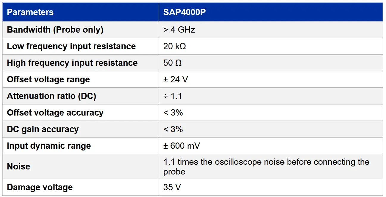
Probe Technical Specifications
SAP4000P is a high-bandwidth power rail probe known for its features such as high bandwidth, low noise, high input impedance and large offset voltage range, making it suitable for power integrity measurements.
The SAP4000P power rail probe utilizes the SAPBus interface and is compatible with oscilloscopes that support the SAPBus interface, such as the SDS3000X HD, SDS5000X, SDS6000 Pro, and SDS7000A series oscilloscopes. The SAP series active probes do not require external power sources as the oscilloscope provides power and communication interface to the active probe through the SAPBus. When connected to the oscilloscope, the SAP series active probes allow you to read probe information from the oscilloscope’s interface.
Here are the performance characteristics:
- Probe Bandwidth: DC to > 4 GHz
- Low frequency input resistance: 50 kΩ
- High frequency input resistance: 50 Ω
- Probe gain: ÷ 1.1
- Noise: 1.1 times the oscilloscope noise before connecting the probe
- ± 600 mV input dynamic range
- ± 24 V offset voltage setting range
- SAPBus interface
Model and Specifications
The specifications of the probe need to meet the following conditions:
- The probe is within its valid calibration period.
- The environmental temperature is within 25°C ± 5°C.
- The probe is correctly connected to the oscilloscope.
- The probe and oscilloscope are in a thermally stable environment, and both the probe and oscilloscope have been preheated for at least 20 minutes.
Probe Model and Specification Parameters:
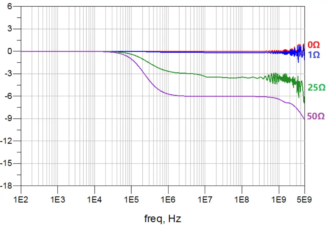
The figure below shows the frequency response of the probe connected to signal sources with different output impedances. It can be seen that when the output impedance of the signal source is very low, the frequency response curve is relatively flat. If the output impedance of the signal source is not low enough, the voltage distribution of the source output impedance and the input impedance of the probe is uneven in the entire frequency band, resulting in a decrease in the gain in the high frequency band. Therefore, it is recommended that the output impedance of the circuit under test should be much less than 1 ohm.
The power rail probe presents high input impedance at DC and low frequencies, so it is a low load (50 kΩ) for the DUT. The low input impedance of 50 Ω at higher frequencies can reduce the noise output by the probe to the oscilloscope and improve the frequency range and accuracy of the measurement. The following figure shows the relationship between the probe input impedance and frequency.

Accessories
SAP4000P has the following accessories:


Main cable: One SMA male connector, one SMA female connector, length 1 meter.

Pigtail cable: One end has an SMA male connector and the other end is for soldering.

SMA-M cable: 6cm long, used to connect the main cable and high speed probe browser.

High speed probe browser: Point test surface mount devices, suitable for 0603 and 0402 packages.

SMA dual lead adapter: Can be directly connected to the pin header or micro capacitor clip.

Micro SMD Clip.

Low Speed Probe Browser.

Two-legged Positioner PP201: For probe fixing.

3D Positioner PP301:For probe fixing.
Probe Dimensions


Probe Operation
The SAP4000P power rail probe is a precision test and measurement instrument. Avoid excessive pulling on the cable during use, and when not in use, store the probe in the provided probe pack.
![]() Electrostatic Sensitive: The probe is sensitive to ESD. When using the probe, adhere to ESD protection procedures.
Electrostatic Sensitive: The probe is sensitive to ESD. When using the probe, adhere to ESD protection procedures.
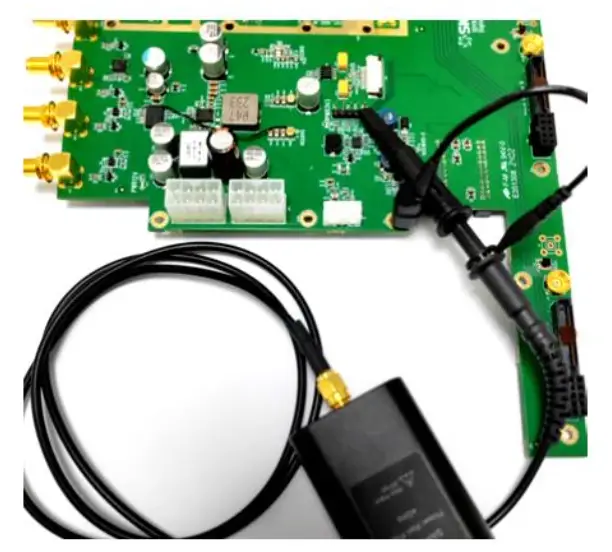
Connecting the Probe to an Oscilloscope
The SAP4000P is compatible with oscilloscopes that support the SAPBus interface, such as the SDS3000X HD, SDS5000X, SDS6000 Pro, and SDS7000A series oscilloscopes.
When the probe is connected to the oscilloscope, the oscilloscope can automatically identify the probe model and adjust display scales and measurements accordingly. Basic information about the probe, such as the model and serial number, can be viewed on the oscilloscope’s user interface. After connecting the probe, the maximum vertical scale on the oscilloscope is 200 mV/div, and the DC offset can be set in the range of ± 24V.
Connecting the Probe to the Test Circuit
Connect using the main cable
The main cable has two SMA interfaces and can be connected to the probe amplifier. The connection is flexible and reliable, and the measurement bandwidth is > 4 GHz. The 1-meter length can be easily connected to the circuit under test without placing the oscilloscope near the circuit under test.

Connect using the pigtail cable
Pigtail cable for use with probe amplifier and main cable. Tip is soldered to the circuit under test, providing a reliable connection and short ground loop. Measurement bandwidth > 4GHz.

Connect using the low speed probe browser
A set of point measurement accessories is formed by using the mechanical parts of the passive probe. It is very convenient to use and can measure 350 MHz bandwidth (with ground spring). Ground wire: The ground wire can be used to connect to a ground position farther away from the measured point
Ground spring: Using ground spring grounding can make low speed browser probe achieve higher performance. Its flexible structure can easily change the spacing between input and ground to adapt to the location of the test point
Connect using the SMA dual lead adapter
SMA dual lead adapter: The SMA dual lead adapter allows easy connection to common 2.54 mm pitch headers. The connection is more reliable and there is no risk of insulation. Measurement bandwidth > 200 MHz.

Micro SMD Clip: The Micro SMD Clip is used with the SMA dual lead adapter to quickly test the power supply signal of surface mount capacitors.

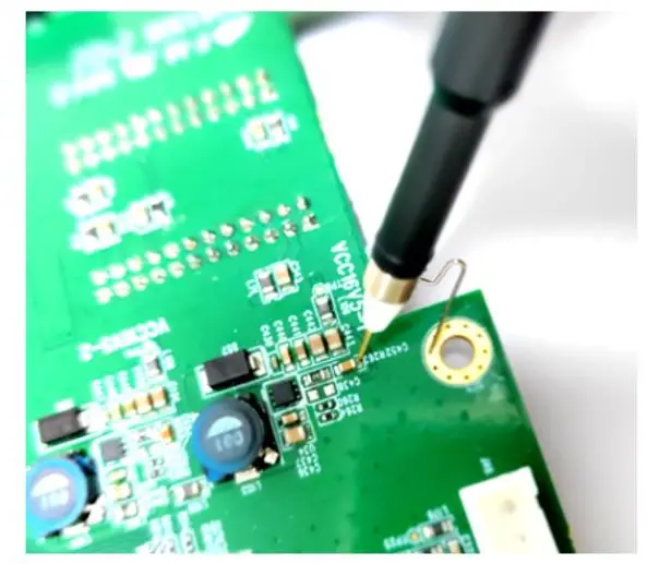
Connect using the high speed probe browser
The high speed probe browser provide a convenient, high bandwidth method for probing surface mount capacitor packages commonly used in power distribution networks. High speed probe browser can be used to test 0603, 0402 packages. Measurement bandwidth > 3 GHz.

Pigtail Cable Welding
Before using the pigtail cable, please read the following instructions carefully, otherwise the cable and the circuit board under test may be damaged.
Soldering method:
- First add a small amount of solder to the device under test.
- Adjust the soldering iron to a suitable temperature (the contact point has a small heat dissipation area, and the soldering temperature cannot be too high, otherwise it is easy to damage the cable).
- First solder the tip of the cable to the power network, and then solder the outer braid of the cable to the ground network.
![]() To avoid overheating and damaging the circuit board, do not allow the soldering iron to contact the solder point for longer than necessary. The solder joints are very small and have low thermal mass, so they will melt quickly.
To avoid overheating and damaging the circuit board, do not allow the soldering iron to contact the solder point for longer than necessary. The solder joints are very small and have low thermal mass, so they will melt quickly.
Probe Fixing Method
When using the probe, the probe can be fixed using the corresponding probe positioner, which can free your hands and make the connection between the probe and the measured point more stable.
Fixing the probe using the two-legged positioner PP201
PP201 is a standard accessory.

Fixing the probe using the 3D positioner PP301
Adjusting the knob of the 3D positioner can adjust the resistance of the three force arms. Turning the knob clockwise increases the resistance and fixes it directly, while turning the knob counterclockwise decreases the resistance.

![]() Do not turn the knob too far counterclockwise, just enough to allow the lever arm to move. Otherwise, the knob may become inoperable and require reassembly.
Do not turn the knob too far counterclockwise, just enough to allow the lever arm to move. Otherwise, the knob may become inoperable and require reassembly.
About SIGLENT
SIGLENT is an international high-tech company, concentrating on R&D, sales, production and services of electronic test & measurement instruments.
SIGLENT first began developing digital oscilloscopes independently in 2002. After more than a decade of continuous development, SIGLENT has extended its product line to include digital oscilloscopes, isolated handheld oscilloscopes, function/arbitrary waveform generators, RF/MW signal generators, spectrum analyzers, vector network analyzers, digital multimeters, DC power supplies, electronic loads and other general purpose test instrumentation. Since its first oscilloscope was launched in 2005, SIGLENT has become the fastest growing manufacturer of digital oscilloscopes. We firmly believe that today SIGLENT is the best value in electronic test & measurement.
Headquarters:
SIGLENT Technologies Co., Ltd
Add: Bldg No.4 & No.5, Antongda Industrial
Zone, 3rd Liuxian Road, Bao’an District,
Shenzhen, 518101, China
Tel: + 86 755 3688 7876
Fax: + 86 755 3359 1582
Email: sales@siglent.com
Website: int.siglent.com
North America:
SIGLENT Technologies America, Inc
6557 Cochran Rd Solon, Ohio 44139
Tel: 440-398-5800
Toll Free: 877-515-5551
Fax: 440-399-1211
Email: info@siglentna.com
Website: www.siglentna.com
Europe:
SIGLENT Technologies Germany GmbH
Add: Staetzlinger Str. 70
86165 Augsburg, Germany
Tel: +49(0)-821-666 0 111 0
Fax: +49(0)-821-666 0 111 22
Email: info-eu@siglent.com
Website: www.siglenteu.com

https://www.facebook.com/SiglentTech
Documents / Resources
 |
SIGLENT SAP4000P Power Rail Probe [pdf] User Manual SAP4000P, SAP4000P Power Rail Probe, Power Rail Probe, Rail Probe, Probe |