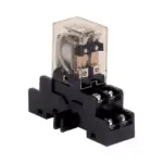
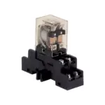
![]() DB2-HR Detector Relay Base
DB2-HR Detector Relay Base
Instruction Manual
DB2-HR Detector Relay Base
Polarity Insensitive wiring: Class X Wiring (Isolator mode):
 * The relay contacts are shown after System reset, which represents the non-alarm condition.
Wires connected to TB3/TB4 must enter or exit electrical box on opposite side of wires connected to TB1, if TB1 is used in an AC Power or Non-Power Limited application.
Figure 1 DB2-HR Wiring for Polarity Insensitive Detectors
DETECTOR AND BASE PLACEMENT
Detector and base locations shall follow the drawings provided or approved by Siemens Industry, Inc. or its authorized distributors. This is extremely important! The detector placements shown on these drawings were chosen after a careful evaluation of all facets of the protected area. When drawings are not available, refer to Detector Placement section of detector Installation/Wiring Instructions and to NFPA 72, National Fire Alarm Code and CAN/ULC-S524.
WIRING
The Model DB2-HR from Siemens Industry, Inc. is a polarity insensitive detector base that is compatible with the detectors listed in Table 1.
| Table 1 compatible Detectors | |
| Detector | Inst. Instr. P/N |
| FD0421 | A6V10323926 |
| FDOOT441 | A6V10324655 |
| FDOOTC441 | A6V10324657 |
| FDOT421 | A6V10323934 |
| FDT421 | A6V10323930 |
| HFP-11/HFPT-11 | 315-033290 |
| HFPO-11 | 315-034800 |
| HI921 | A6V10323932 |
| OH921 | A6V10323936 |
| 00H941 | A6V10324659 |
| 00HC941 | A6V10324661 |
| OP921 | A6V10323928 |
| SFP-11/SFPT-11″ | 315-033290C |
| SFPO-11* | 315-033290C |
| 8710, 8712, 8713 | 315-033290FA |
| *SFP-11, SFPT-11 and SFPO-11 detectors are approved for use in Canada only | |
Detector base should be interconnected as shown in Figure 1 and wired to the device loop of the control panel. Line 1 and Line 2 can be either line of the loop. Note any limitations on the number of detectors and restrictions on the use of remote devices permitted for each circuit. For maximum number of devices, refer to the panel power calculations in the PSC-12 manual, P/N 315-033060.
Note:
Recommended wire size:
18 AWG minimum
14 AWG maximum
Wire larger than 14 AWG can damage the connector.
POWER LIMITED WIRING
In compliance with NEC Article 760, all power limited fire protective signaling conductors must be separated a minimum of1/4 inch from all of the following items located within an outlet box:
- electric light
- power
- Class 1 or non-power limited fire protective signaling conductors
To meet the above the requirements, the following guidelines must be observed when installing this relay base module.
MODULE BARRIER
The Module Barrier must be used when the DB2-HR relay contacts are connected to non-power limited lines. Break apart the barrier to the correct size and shape shown in Figure 2 for the 4-inch square box. Install the barrier diagonally into the back-box to create two separate compartments within the backbox to separate the wires, as shown in Figure 2.
 Figure 2 Installing the Control Module Barrier
WIRING ENTERING OUTLET BOX
Power Limited Wiring
All power limited wiring must enter the outlet box separately from the electric light, power, Class 1, or non-powered limited fire protection signaling conductors. For the DB2-HR, wiring to terminal blocks TB3 and TB4 must enter the outlet box separately from wiring to terminal block TB1.
Important : Minimize the length of wire entering the outlet box.
DETECTOR MOUNTING USING THE DB2-HR BASE
The detector is mounted on the DB2-HR base which attaches to a standard 4 inch square electrical box, with the box size and depth required by the NEC for the number and size of conductors used. Wire to the terminal blocks as shown in Figure 1. Wire size: max – 14 AWG, min – 18 AWG.
- After all bases are installed, check wiring integrity.
- To insure proper installation of the detector head into the base:
a. Make sure that existing wires are away from connector terminals.
b. Check that screw terminals are tight.
 Figure 3 Mounting the Detector into the DB2-HR Base
CYBER SECURITY DISCLAIMER
Siemens provides a portfolio of products, solutions, systems and services that includes security functions that support the secure operation of plants, systems, machines and networks. In the field of Building Technologies, this includes building automation and control, fire safety, security management as well as physical security systems.
In order to protect plants, systems, machines and networks against cyber threats, it is necessary to implement – and continuously maintain – a holistic, state-of-the-art security concept. Siemens’ portfolio only forms one element of such a concept. You are responsible for preventing unauthorized access to your plants, systems, machines and networks which should only be connected to an enterprise network or the internet if and to the extent such a connection is necessary and only when appropriate security measures (e.g. firewalls and/or network segmentation) are in place. Additionally, Siemens’ guidance on appropriate security measures should be taken into account. For additional information, please contact your Siemens sales representative or visit https:// www.siemens.com/global/en/home/company/topicareas/future fmanufacturingindustrialsecurity.html.
Siemens’ portfolio undergoes continuous development to make it more secure. Siemens strongly recommends that updates are applied as soon as they are available and that the latest versions are used. Use of versions that are no longer supported, and failure to apply the latest updates may increase your exposure to cyber threats. Siemens strongly recommends to comply with security advisories on the latest security threats, patches and other related measures, published, among others, under https://www.siemens.com/cert/en/cert-security-advisories.htm.
![]() Siemens Industry, Inc.
Siemens Industry, Inc.
Smart Infrastructure
Florham Park, NJ
Siemens Canada, Ltd.
1577 North Service Road East
Oakville, Ontario
L6H 0H6 Canada
Document ID A6V10327325_en–_b
firealarmresources.com
Documents / Resources
 |
SIEMENS DB2-HR Detector Relay Base [pdf] Instruction Manual DB2-HR Detector Relay Base, DB2-HR, DB2-HR Detector Relay, Detector Relay Base, Detector Relay, Relay Base, Relay |