Shivvers 702E-001A Continuous Flow Transfer Auger

Specifications
- Model Numbers: 702B-001A, 702E-001A
- Manufacturer: Shivvers Manufacturing, Inc.
- Address: 614 W. English Street Corydon, IA 50060
- Contact: PH 641-872-1005, FAX 641-872-1593
Product Usage Instructions
Installing the Quick Release Powerhead onto the Auger
To install a 702B-001A QRPH or 702E-001A QRPH onto an 8-inch Shivvers Continuous Flow/Transfer Auger:
- Locate the Flipper Shaft and Flipper Shaft Hardware Sack.
- Install the Flipper Shaft into the end of the Basic Flite Weldment.
- Remove the Outer Bearing/Mount from the Backplate Assembly.
- Place washers onto the Flipper Shaft in front of the Bearing and install the Roll Pin to secure them.
Motor Installation
- Install the motor ensuring proper center distance from the Motor Shaft to the Flipper Shaft based on the provided chart.
- Place the square drive key into the Flite Shaft and install the Pulley onto the Flipper Shaft securely.
SHIVVERS MANUFACTURING, INC. 614 W. ENGLISH STREET CORYDON, IA 50060
To Install a 702B-001A QRPH (Quick Release Power Head-3-Belt Drive) or 702E-001A QRPH (Quick Release Powerhead 4-Belt Drive) onto an 8-inch Shivvers Continuous Flow/Transfer Auger:
Note:
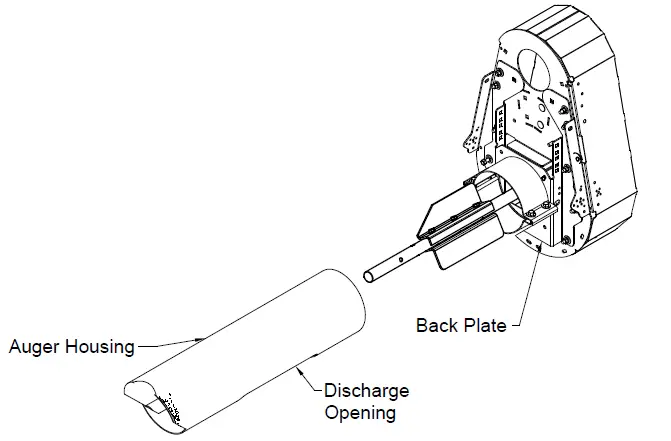
This drive unit will bridge over the area where the Discharge Spout is installed, so the spout will be installed after the QRPH is in place. This drive unit is not designed to replace a 672-style Powerhead. With the pre-assembled Continuous Flow/Transfer Auger at ground level, install the QRPH:
- Locate the Flipper Shaft 702-164A and the Flipper Shaft Hardware Sack, 702-058A. Install the Flipper Shaft into the end of the Basic Flite Weldment.
- Locate the 702-057A QRPH Hardware Sack.
- Remove the Outer Bearing/Mount together as a unit from the Backplate Assembly. (This gives access to perform the next few steps. You will be instructed to re-install this unit later).

ATTENTION INSTALLER:
The unit is assembled with the bearing grease zerk pointing to the left. The bearing and plate can be rotated 90 degrees left, right, or down for better access depending on the installation. The outer bearing must stay in the down position. Install the pre-assembled Backplate onto the end of the Basic Transfer Auger Section with the Flipper Shaft extending through the Bearing. Orient the QRPH so that the drive assembly will be 180 degrees opposite the discharge opening. Slide Backplate Assembly onto the discharge end of the Basic Transfer Auger’s Housing until the end of the housing contacts the back surface of the backplate. A large rubber mallet may be required to get the Backplate Assembly into place. Secure the backplate into position by tightening the halfband bolts.
Place three or four Large Washers (from the Flipper Shaft hardware sack) onto the Flipper Shaft in front of the Bearing. Install the Roll Pin, trapping the washers between the roll pin and the bearing. Slide the Flipper Shaft back until the Washers are tight against the Bearing.

- Install the Rear Frame Wldt 702-032W and 3-Eared Halfband 397-002W. (Install the fasteners, but do not tighten).
- Consult the Motor Mount Chart for proper positioning.
- Install Motor Mount Bracket 702-025P to Backplate Assembly and Rear Frame Weldment according to proper mounting position for the motor.
- Carriage Bolts may be installed either with the heads out (for better appearance) or with the threads out for easier assembly.
- With the Rear Frame Weldment, Motor Mount Bracket, and Backplate Assembly in place, tighten all the fasteners securely.
Note:
The positions listed in the table below are starting recommendations. Measurements between the motor and auger shafts must be checked by the installer for accuracy before operation.

MOTOR MOUNT CHART

- Install the Motor. (the center distance from the Motor Shaft to the Flipper Shaft should be about 15-1/4”`1/4″) (Note: The Belt Idler Assembly must be fully installed before installing the Motor since the mounting bolt for it is trapped between the Backplate and the front of the motor).
- Place the long square drive key (702-071P) 1/4 x 1/4 x 2-3/4” L into the Flite Shaft. Apply Anti-Seize compound to the Flipper Shaft and Key where the Pulley Hub will be.
- Install the 15-in Aluminum 3AB Groove Pulley (D-3837)[702B-001A] or the 4AB Groove Pulley (D-3883 and Hub, D-3884)[702E-001A] onto the Flipper Shaft with the setscrew side of the Hub Out.
- With 1-1/8” between the Backplate and the back of the pulley, tighten the pulley’s setscrew securely.

- Apply an anti-size compound to the Motor Shaft. Install the Motor Pulley (ordered Separately), onto the Motor Shaft. Align with the large Pulley and tighten in place.
- Re-install the Outer Bearing Mount (removed earlier) onto the end of the Flipper Shaft and fasten it securely to the bracket on the Backplate Assembly. Tighten the setscrews of the bearing to the Flipper Shaft.

Check the Belt Guard, There should be (2) 1/4” x 5/8” Bolts in the flange of the Belt Guard that interlock with the Backplate. If they are not there, it is recommended that some be installed. These help the Latch hold the Belt Guard in place when latched.

Cut the Wire Ties holding the Tensioning Linkage, then actuate the Tensioning Arm outward to retract the Idler Assembly. Place a small amount of grease around the outside groove of the Tensioning Pivot (702-035P) where the Tensioning Linkage snaps into position when tightened.

- Install the Drive Belts D-3863 (BX62 Cogged Belts for 702B-001A) or D-3887 (BX64 Cogged Belts for 702E-001A). Note Clockwise Rotation.
- Actuate the Tensioning Arm inward to tighten the Belts.
- Loosen the nut holding the Idler in place and slide it toward the Belts to take up most of the slack. (It may be necessary to tap the end of the Carriage bolt in the center of the Idler to loosen it so the Idler Pulley will slide in the slot).
- Actuate the Tensioning Arm outward and slide the Idler in the slot an additional 1/4”. Actuate the Tensioning Arm inward to tighten the Belts.
- Fine-tune the Tightening with the Adjustment Nut and Spring on the Tensioning Linkage where it comes through the Idler Arm Wldt.
- Rotate the Drive a few times making sure there is adequate clearance between the Drive Pulleys and V-Belts, and the Tensioning Linkages. Tighten the Pintle Latch so there will be no torsion on thebelt’ss idler.

With the Drive fully assembled and adjusted, Shut the Belt Shield and Latch it in place. Install the Discharge Spout (273I-001A)

Frequently Asked Questions
Q: Can the Quick Release Powerhead be used with any other type of auger?
A: No, this drive unit is specifically designed for use with an 8-inch Shivvers Continuous Flow/Transfer Auger and is not meant to replace a 672-style Powerhead.
Q: How should I position the bearing and plate during installation?
A: The unit is assembled with the bearing grease zerk pointing to the left. The bearing and plate can be rotated 90 degrees left, right, or down for better access, but the outer bearing must stay in the down position.
Documents / Resources
 |
Shivvers 702E-001A Continuous Flow Transfer Auger [pdf] Installation Guide 702B-001A, 702E-001A, 702E-001A Continuous Flow Transfer Auger, 702E-001A, Continuous Flow Transfer Auger, Flow Transfer Auger, Transfer Auger |