![]() Single Beam Sonar
Single Beam Sonar
HydroLite Plus Single Frequency
Instruction Manual
Introduction
Overview
The HydroLite Plus Single Frequency system is a hydrographic grade echosounder kit.
This system’s rugged design and flexibility address the need for general land survey applications and more detailed hydrographic surveys. The system has the ability to integrate with traditional land survey data collectors and software to generate generic bottom track elevation data. It can also output high quality echogram data into dedicated collection software to post process the bottom track more accurately.
Components *GPS & data collector not included
HydroLite Plus topside
HydroLite Plus transducer
Charger
Data cable
RS232 – USB adapter
3x Poles
Transom mount
4mm allen Driver
Null modem
Gender changer
Warranty Information
Seafloor Systems, Inc. makes every effort to assure its products meet the highest quality, reliability and durability standards and warrants to the original purchaser or purchasing agency that each HydroLite Plus be free from defects in materials or workmanship for a period of one year from date of shipment.
Warranty does not apply to defects of misuse, negligence or accidents. Warranty also does not cover repairs or alterations outside of our facilities, or use of the HydroLite Plus for purposes other than water measurements. Seafloor is not responsible for loss of instruments, damage to property, or injury/death associated with the use of any of its products or 3rd party products that may be included or used with Seafloor products. Seafloor does not warranty third-party products sold by Seafloor. These may include GPS, depth sounders and other ancillary equipment. All warranty services are FOB Seafloor’s facility in Shingle Springs, California, U.S.A.
Assembly
To assemble the HydroLite Plus, attach the transducer to one of the provided survey poles. Loosen the locking nut on the Transom Mount and slide the pole through both holes, tighten the locking nut when in the desired position. When mounting on the side of a vessel, ensure that the pole is as close to vertical as possible. Additional 2ft pole sections can be threaded on.
Attach the HydroLite Plus topside to the pole using the included allen driver and plug in the transducer cable. To the “Sonar/Charger” port. The included MilSpec-RS-232 cable attaches to the RS-232 port. Note – When this is plugged in, Bluetooth output is disabled.
Connection – Windows Device
Power on the HydroLite Plus by pushing the button the front face of the unit. This system is capable of connection over either Bluetooth or hardwire connection.
Bluetooth – Connection and Com Port
- Open Settings in Windows 10/11
- Select Bluetooth and Devices
- Add Device
a. Device ID: HYDROLITE### (serialized per device)
b. Password: SEAFLOOR - Open Control Panel > Hardware and Sound > Devices and Printers (Win 11 when in Hardware and Sound, right click Devices and printers and select Open in New Window)
- Scroll to the bottom where the “Unspecified” devices are. Double Click the HydroLite and navigate to the Hardware Tab. From there, Note the COM number assigned to the Device. See figure on next page.
 Hardwire – Connection and Com Port
- Connect the Milspec-RS232 cable to the sonar port on the HydroLite Plus Topside.
- Connect the system to the RS232-USB adapter supplied with the system.
- Open Device manager and select the dropdown for Ports (COM & LPT)
- Plug in the USB Adapter and it should automatically download and install the correct driver for the device. A new port should appear with a COM number assigned to it. (If it doesn’t, Look under Other devices and see if the adapter is under that category. The driver needed for this adapter is called CH340. See image on next page.
Offset
Enter rod height from: 
 Device Settings
Control Program
The control program is included on the USB dongle, if misplaced it is also available on seafloorsystems.com
Connect to the control program by selecting the COM port assigned to the echosounder.
Echosounder default baud rate: 115200
GPS: None
Once connected you can use this program to monitor your bottom track as well as change the parameters of the system to better suit the environmental condition.  On the left-hand side of the window you can see the different parameters that can be changed.
On the right will be a bottom track of the system returns this can be utilized to better tune the system.
Bottom left will display information regarding the transducer status, and bottom right displays the terminal commands being broadcast.
Parameters
The setup parameters are as follows:
- Range, m
o Range in meters - Tx length, μsec
o Set transmitted pulse length in microseconds. (Up to 100 μsec) - Interval, sec
o Interval (repetition rate) between pulses in seconds. (From 0.1 to 3600 (1 Hour)) - Deadzone, mm
o Near field zone where detection is ignored - Offset, mm
o Vertically offset the position of the device in millimeters. - Altimeter threshold, %
o Altimeter threshold percentage of full scale (return sensitivity) - Gain, dB
o Analog gain of amplifier in dB - Sound Speed, m/s
o Speed of sound in water - Output mode
o Select output data formats
 – Altimeter simple
– Echosounder
– Altimeter NMEA
– Echosounder fixed 200 samples
– Echosounder fixed 500 samples
– Echosounder fixed 1000 samples
– PSA-916
– Altimeter simple & temperature
– Hydrolite DFX
– Hydrolite OLD
Each of these settings can be adjusted by using the drop-down menus. For the settings to be updated on the echosounder, one must hit “Apply” after any changes are made. There are range limitations for certain intervals, baud rates, and output modes. See next page for more information.
Baud Rate: 115200 bps
| Altimeter Mode | |
| Interval (sec) | Maximum Range (m) |
| 0.1 | 10 |
| 0.2 | 40 |
| 0.25 | 80 |
| 0.3 | 100 |
| Echosounder Mode | |
| Interval (sec) | Maximum Range (m) |
| 0.1 | — |
| 0.2 | 1 |
| 0.25 | 2 |
| 0.5 | 8 |
| 1 | 20 |
| 2 | 80 |
| 2.5 | 100 |
Baud Rate: 921600 bps
| Altimeter Mode | |
| Interval (sec) | Maximum Range (m) |
| 0.1 | 15 |
| 0.2 | 40 |
| 0.25 | 100 |
| 0.3 | 100 |
| Echosounder Mode | |
| Interval (sec) | Maximum Range (m) |
| 0.1 | 2 |
| 0.2 | 10 |
| 0.25 | 15 |
| 0.5 | 30 |
| 1 | 100 |
Echogram
The Echogram is an important feature of this system when data is being collected in software that can utilize the results to better post process. This is also a useful tool for configuration and troubleshooting issues. Below is an example of the echogram window and descriptions of the different functions. 
- Data scale: Echo signal can be changed between linear scale and dB scale
- Data output: Display max or mean amplitude
- Range: Sets the range of the echogram shown on screen (does not affect raw data)
- Color palette: Select different color schemes
When the real time returns are being shown in the echogram, the altitude is determined when the signal passes the set threshold parameter. For this reason, altitude threshold, deadzone, and gain are the important settings when tuning the system. See example on the next page.  All tuning should be conducted with the output mode: echosounder
Notice that the circled altitude is reporting a depth of 0.387 m. This is due to the initial reverberation
(1), being picked up as a return.
To avoid this, make sure that the dead zone parameter, is large enough to bypass the reverberation and track the real reflection (2).
In altimeter modes (simple, NMEA, PSA-916, OLD Hydrolite) increase the gain, so the return signal can be saturated enough to strongly reflect the true bottom.
Furthermore, the altitude threshold should be as small as possible without generating returns off of the unwanted signals. If this is not set properly, the system will generate false returns from reflections in the water column and not off the true bottom.
Seafloor settings:
| Range: | 100000 |
| Tx Length | 100 |
| Interval | 0.5 |
| Deadzone | 300 |
| Offset | 0 |
| Altimeter Threshold | 10 |
| Gain | 6 |
| Sound speed | 1500 |
| Output | OLD |
| Mode | Hydrolite |
Terminal
The system can also be connected to a terminal program to quickly check and adjust settings or view the data being output. This is an alternative to the control program for adjusting settings, not recommended for tuning the system. The terminal can be used to alter the NMEA messages as well as adjust the baud rate of the system. These adjustments cannot be made in the control program and must be edited through the terminal program. See example below of the terminal program displaying settings of the echosounder. Connect
Open TeraTerm. Click Setup>Serial port. Select the com port assigned to the system either hardwired or Bluetooth. Adjust baud rate to 115200. Then click “New Setting” to open the port.
Once connected, data will start coming across. To issue commands the data coming in needs to be stopped by pressing the space bar.
Commands
The next page contains a list of commands that can adjust the settings of the system.
| Command | Sample of input/output | Comments |
| #range | #range 10000 <ENTER> or >#range <ENTER> >Input Value: 10000<ENTER> >ok. |
Set range in mm, from 1000 mm to 100000 mm |
| #interval | #interval 0.5<ENTER> or ># interval <ENTER> >Input Value: 0.5<ENTER> >ok. |
Pulse repetition rate. Set interval between pulses (pings) in seconds. From 0.1 to 3600 seconds |
| #threshold | #threshold 10<ENTER> | Set altimeter threshold in %% of Full Scale (maximum amplitude of echo signal) |
| #offset | #deadzone 200<ENTER> | Set offset of output altitude in mm |
| #deadzone | #offset 0<ENTER> | Set minimal deadzone in mm. |
| #txlength | #txlength 20<ENTER> | Set transmitted pulse length in microseconds. Max. value 100 uks. |
| #output | #output 1<ENTER> | Set Output mode. 1- Altimeter Simple 2- Echosounder 3- Altimeter NMEA 4- Echosounder Fixed 200 Samples 5- Echosounder Fixed 500 Samples 6- Echosounder Fixed 1000 Samples 7- PSA-916 8- Altimeter Simple & Temperature 9- Hydrolite DFX 10- Hydrolite OLD Echosounder Fixed 1000 Samples |
| #gain | #tvgmode 1<ENTER> | Set analog gain of preamplifier in dB. |
| #tvgmode | #gain 3<ENTER> | Set TVG mode (Time Variable Gain). Only for debugging. Default value: 1. |
| #tvgs | #tvgs 1<ENTER> | Set slope TVG curve. Only for debugging. Default value: 1. |
| #speed | #speed 4800<ENTER> | Set serial port speed in bods. User can set: – 4800 – 9600 – 19200 – 38400 – 57600 – 115200 – 230400 – 460800 – 921600 |
| #nmeadbt | #nmeadbt 1<ENTER> | $GPDBT message enable – 1, disable – 0 |
| #nmeadpt | #nmeadpt 1<ENTER> | $GPDPT message enable – 1, disable – 0 |
| #nmeamtw | #nmeamtw 1<ENTER> | $GPMTW message enable – 1, disable – 0 |
| #nmeaxdr | #nmeaxdr 1<ENTER> | $GPXDR message enable – 1, disable – 0 |
| #nmeaema | #nmeaema 1<ENTER> | $GPEMA message enable – 1, disable – 0 |
| #sound | #sound 1500<ENTER> | Set sound speed in water. |
| #help or #info |
#info > Info ———————————————– Ultrasonic Echo Sounder ECHOLOGGER EU200 / ECT200 / ECS200 / EGT200 Made by EofE Ultrasonics Co., LTD(C) Version 3.3 Jun 10 2022 12:31:27 Device ID: 0643 Echologger 200000 Hz Type USB / RS-232, 422, 485 Specification: * Tx Frequency 200000 Hz * Work Max Range 100m * Tx Length 20~100 uks * Speed of Sound 1500 mps Water Temperature [Celsius]: 20.24°C Tilt Sensor: Pitch(X-axis inclination),degree 0.000 Tilt Sensor: Roll (Y-axis inclination),degree 0.000 Tilt Sensor is absent! B64INFO[gwIAA KC GA QBkAAAAAD8sA QAAC gAAAMBAAAC APwEACgDcBQAAAAA AA AA AheuhQ QAA] Commands: ————————————————————————— – #help – #go (goto Work Mode) – #default (set default Settings) Device ID: 0643 Echologger 200000 Hz Type USB / RS-232, 422, 485 – #range [100000 mm ] Range, 1000 ~ 100000 – #interval [ 0.50 sec ] Interval between pulses, 0.1 ~ 100000 – #threshold [ 10 % ] Threshold, 0 ~ 100% Full Scale – #offset [ 0 mm ] Offset, -+1000 – #deadzone [ 300 mm ] Dead Zone 0 ~ 1000 – #txlength [ 100 uks ] TX Pulse length, 10 ~ 100 – #sound [ 1500 mps ] Sound speed, mps – #output [ 10 ] Output format 1 ~ 10 1: Altimeter Simple 2: EchoSounder 3: Altimeter N MEA 4: EchoSounder Fi xed 200 Samples 5: EchoSounder Fi xed 500 Samples 6: EchoSounder Fi xed 1000 S mples a 7: PSA-9 16 8: Altimeter Simple & Temperature 9: Hydrolite DFX 10: Hydrolite OLD – #gain [6.0 dB] Analog Gain, -30~+30 – #tvgmode [1] TVG Curve type, 0,1,2,3 – #tvgs [1.00] TVG Curve Slope, 0.1~10 |
Show device state and information about parameters and commands. |
| #go | <ENTER> | Start send pulses and receive echo signal |
| #default | #go<ENTER> | Set default values: – range: 10000mm – interval: 1 sec – deadzone: 300 mm – offset: 0mm – threshold: 10% – txlength 20 uks – gain 0 dB – tvgmode: 1 – tvg slope 1 output mode: NMEA |
Software Integration
Trimble Access
Output Format: Hydrolite OLD
Data Example: 1 0.00 0 0 0 11.0 100 0
Connection Guide:
To Configure Survey Style
Upload custom style sheet (delimited w/depth applied).
From the Trimble Access menu, tap settings / survey styles /<Style name>
Trimble Access
Output Format: Hydrolite OLD
Data Example: 1 0.00 0 0 0 11.0 100 0
Connection Guide:
To Configure Survey Style
Upload custom style sheet (delimited w/depth applied).
From the Trimble Access menu, tap settings / survey styles / <Style name>  Tap Echosounder. Select an instrument from the type field. Configure
  Configure the Controller port: If you set the Controller port to Bluetooth, you must configure the Echosounder bluetooth settings. If you set the Controller port to COM 1 or COM 2, you must configure the port settings.
  Latency and draft are normally left at 0. The latency caters for echo sounders where the depth is received by the controller after the position. General survey software uses the latency to match and store the depth when it is received with continuous topo points that were saved previously. Tap accept and then tap Store to save changes.
  Bluetooth Partnership
Tap Settings from the main Trimble Access menu. Tap connect to continue.
Select Bluetooth.
Survey styles – log by time, GPS output every .5 seconds  Tap Config and make sure that Bluetooth is switched on. On a TSC2 controller, make sure that the [turn on Bluetooth] and [Make this device discoverable to other devices] check boxes are selected. On a Trimble CU (model 3) controller, select the power tab and then make sure that the [enable Bluetooth] and [Discoverable] check boxes are selected. On a Trimble CU controller, make sure that the [Enable Bluetooth] checkbox is selected.
 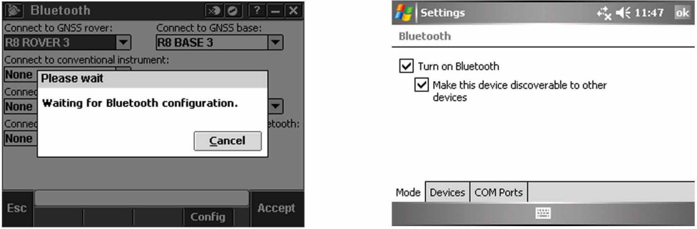 Start a scan on the controller. On a Trimble Tablet, Tap [Add a device]. On a TSC2 controller, tap the [devices] tab and tap. [New Partnership…]. On a Trimble CU (Model 3) controller, tap the [scan device] tab and then tap [scan]. On a Trimble CU controller, tap [Scan Device]. (Do not use [stop] – wait for the scan to complete.) Tip – Be sure that the transducer is plugged into the TXR before selecting the Bluetooth partnership.
 Start a scan on the controller. On a Trimble Tablet, Tap [Add a device]. On a TSC2 controller, tap the [devices] tab and tap. [New Partnership…]. On a Trimble CU (Model 3) controller, tap the [scan device] tab and then tap [scan]. On a Trimble CU controller, tap [Scan Device]. (Do not use [stop] – wait for the scan to complete).
 The controller searches for other Bluetooth devices within range. Once the scan is complete, highlight the Bluetooth device to connect to: On a Trimble Tablet tap [Next].
 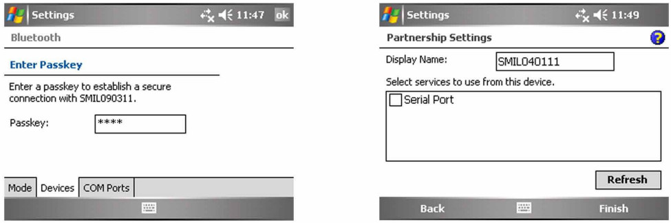 The Bluetooth Pin for this is set to: SEAFLOOR
Leave the serial port box empty. Tap finish and the Bluetooth will be configured.
Trimble SCS900
Output Format: Hydrolite OLD
Data Example: 1 0.00 0 0 0 11.0 100 0
Connection Guide:
Summary
Brief instructions on how to use SCS900 and HydroLite Plus echosounder for a small hydrographic survey.  In Trimble’s SCS900 software it is possible to combine the depths of a HydroLite Plus echosounder and the positions or optical instruments.
In order to do so, a DLL and program should be stored in the following order \Program Files \Trimble SCS900 there are different programs available, one for each type of data logger. In this document the TSC2 was used (Windows Mobile 5).
It is possible to create a shortcut of the executable in the folder \Windows\Start Menu enabling the software to be started from the start menu. First of all, the echosounder should be connected to the data logger, this can be done using a serial connection, i.e. via
Bluetooth (it is also possible to use a serial cable if the GPS receiver supports.
Bluetooth).
Pairing Bluetooth Devices
Assuming the Hydrolite Plus is not paired yet, go to Start>Settings>Connections and select Bluetooth. Make sure the checkboxes are both ticket (turn on Bluetooth and make this device discoverable to other devices) now select the page devices. At this stage, turn on the already charged Hydrolite Plus by connecting the transducer (the green light flashes briefly) now select new partnership and the scanning procedure will start. After all discoverable devices are found, select the HydroLite Plus(Device will appear as HydroLite###)and select next.  Enter the Passcode (SEAFLOOR in all capital letters) and enter the partnership settings, by checking the serial port service. After this, the Hydrolite is visible under the tab Devices.
  After this, the serial port has to be assigned by selecting the tab COM ports and select New Outgoing Port. Again select the HydroLite and select Next. Now deselect (uncheck) secure connection and select Finish. Remember the comport number assigned to this service (in this case COM 8)
  Starting a Hydrographic Survey
In order to combine the depths from the Hydrolite and the positions in SCS900 it is essential the Hydrolite software is started and remains running during the survey.
Starting the Hydrolite Software
If a shortcut is created, select Start>SMtsc. If the shortcut is not created, find the executable located under \Program Files\Trimble SCS900. If the software is not registered, please register on Ohmex’s website http://ohmex.com/register.htm  Now select Device>Hydrolite and select the previously assigned COM port (in this case COM 8) Leave the other settings as per default (As the baud rate is capped at 38400, the output speed will need to be changed in the HydroLite Terminal Program (#speed 38400) See Terminal Section for commands) Select OK and the echo sounder should now return depths. It is possible to fine-tune the Quality threshold, it is advised to leave it low in order to pass all data. Leave the Hydrolite software running and continue with the next part. If you encounter problems (unable to connect etc) reset the TSC2 (switch Bluetooth back on) and retry. If this fails, start from the beginning (pairing devices)
In the latest version of the Hydrolite SW or SCS900, it is now possible to set the sound velocity. To do this, double tap the center of the Hydrolite screen and the following display appears.  The functions that display, select Device>Hydrolite and select the previously assigned COM port (in this case COM 8) Leave the other settings as per default (9600,8,n,1 no flow control) Select OK and the echo sounder should now return depths. It is possible to fine-tune the Quality threshold, it is advised to leave it low in order to pass all data. Leave the Hydrolite software running and continue with the next part. If you en-counter problems (unable to connect etc) reset the TSC2 (In this document I assume the user is familiar with the basics of SCS900.
The concept of Sites, Designs and Work orders are assumed as common knowledge. If not, please refer to the SCS900 manual. If a folder structure is prepared by the Survey office, simply start SCS. If not, it is assumed the following files are selectable on the data logger:
- Design (DXF or TTM)
- Site Calibration (or DC file)
- Control points or Bench Marks (TXT)
- Background map
In this example we take this step, which is not required if a folder structure is prepared by the Survey office.
Before starting the Hydrographic survey, be sure to check the system setup by measuring a bench mark. Start SCS900 and create a new Work Order Select the site or create a new one (A site contains the items mentioned above) in this case a new site is created. In the new site, the various files are selected, a minimum is the site calibration file (DC file) in order to get the proper coordinate system, or a csv file containing control points (Since it is recommended to check the system setup, a .csv file is important).
Currently this site calibration can contain a Geoid model, but CAN NOT contain a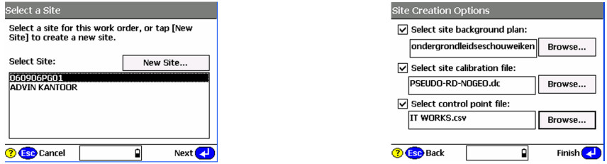 If no calibration file (DC) is at hand, it is possible to calibrate the site using the known points in the .csv file. Simply select calibrate site in the Systems Setup menu.
System Settings
It is possible to set the required accuracies under Settings , this can vary from one jobsite to another. There is a difference in acceptance criteria (will it store a position and depth or not) and the Calibration tolerance (will it accept a System Setup check)  System Setup
Now it is time to start the rover, Select System Setup and Setup Rover, or go directly to Measure Surface. Topo Surface and SCS900 will prompt you to set up a GPS rover. In this process, follow the instructions on screen  The instructions will take you step by step through the system setup. It will ask you if the receiver is connected by cable or Bluetooth (a), if it uses an internal, external radio or other correction method (b), and the coverage map grid size and antenna height (c)
  Once started , SCS900 will ask you if you want to check the system setup, it is advised to do so. After the System Setup is completed and checked, the topo survey can start. Bear in mind there are survey methods, shown in the top left corner. These are Standing (red figure) Walking (yellow figure) and on vehicle mode (yellow quad) Those methods automatically set the position update rate and the different antenna heights. Changing this mode can be done by clicking it. For a hydrographic survey, select the vehicle mode (click here) and enter the height from the bottom of the transducer to the bottom of the antenna.
  Finally select the measurement density required for the job, this will make the system log at a minimum interval or elevation change.
Are you recording the bottom?
In order to check if the system is indeed setup to record the bottom, look at the difference of the elevation shown on top of the screen and the recorded point elevation. To annotate points with their elevation, select the take the following steps. Select the button 123 Des (buttons may be changed by selecting the black triangle) Check display Point Elevations and select OK.  Remember that if loads of points are stored, this option can slow down the CE device and make the map hard to read, so switch off again if required.
Now start a measurement, SCS900 will prompt you for a point name (this will increment automatically) and a code (tip, this code can be used to identify a cross section number or profile number) After selecting OK again, a point is measured and stored, and annotated with the actual height. In this example, the elevation of the bottom of transducer was 5.330, the measured depth was 0.377 (bucket) and the bottom is in that case 4.953.  Complete Work Order
Once finished with the survey, the export files are written in the export folder those files consist of a record.TXT and report.txt optional a DXF can be written but remember this can consume a lot of memory.  Terrasync
Output Format: Altimeter NMEA
Data Example: $DBT,0.00,f,0.00,M
Set Speed to 38400 in Terminal by using the command:
#speed 38400
Connection Guide:
Make Bluetooth connection to Hydrolite using Trimble Settings menu:
Start -> Settings -> Connections -> Bluetooth
Ensure Bluetooth is turned on
Search for Devices -> Select Hydrolite Serial Number
(HydroLite###) Pass Key is SEAFLOOR
Leave “Serial Port” box unchecked
Tap “COM Ports” tab which is located to the left of the “Devices” tab after connecting to the Hydrolite.
Assign the Hydrolite an Outgoing Port so that is what is used.
If under COM Ports the HydroLite Plus is not listed as (COM5) go back to Devices and disconnect the Bluetooth connection to the Hydrolite by clicking and holding on the Hydrolite device and clicking delete. Start again at the top of this block of directions by searching for the Hydrolite.
Configure Terrasync to use Hydrolite as an External Device
Always check that the options below are selected correctly. It does seem that as long as Sensor 2 is selected, all of the options are saved correctly.
- Tap upper dropdown and select “Setup”
- Tap “External Sensors” (bottom right corner)
- Make sure that Sensor 2 is checked (or Hydrolite) and tap “Properties”
- Set “Port” to the COM you assigned the Hydrolite to (COM5: SMIL201215)
- Baud: 4800
- Data Bits: 8
- Stop Bits: 1
- Parity: None
- Set Prefix to: $SMDBT
- Set Suffix to: ,f
- This will bring depths in as feet
- For depth in meters Set prefix to: ,f and suffix to: M,
- Max Bytes: leave blank
- Time Out: 0.00s
- Set Receive mode: Unsolicited
- Logging Intervals (Point Feature, Line/Area Feature, Not in Feature): ‘All’ for them all
- Data Destination: Uninterpreted
Configure the rest of Terrasync as you normally would (you can collect continuous data in either “point” or “line” survey modes)
- Start logging data to a file to check that the Hydrolite is outputting data
- Tap upper dropdown and select “Status”
- Tap lower dropdown and select “Sensor”
- Verify that the sensor is active and sending numerical data. Numbers should be increasing
Data Export using Pathfind Software
Under the data tab, below the Create Point Features From section Make sure ‘Sensor Records’ is checked. This is not a default.
TopCon
Output Format: Altimeter NMEA
Data Example: $DBT,0.00,f,0.00,M
Connection Guide:
Note: The output baud rate may need to be adjusted
GNSS receiver and Depth Sounder
Topcon Technical Support – Product: Magnet field basic set up for Depth Sounder
These instructions are basic depth sounder set up for further detail in the equipement being used it will depend on the hardware and configuration being used (RTK, Optical, Network RTK, DGPS)
 Add a new Confirguration or you cand edit an existing one I Choose the correcion type
  >>>Next 3 Times the Perirals set up button will be available I Also remember to use the correct driver for the depth sounder if driver not available select generic NMEA and the port information default is Bluetooth but serial is incorraged
 Also remember that you can go to the topo module, then to the map view and tab on the screen to select depth
Note: Newer 2013 and 1/2 models use baud rate of 4800
Leica Captivate
Output Format: Hydrolite OLD
Data Example: 1 0.00 0 0 0 11.0 100 0
Connection Guide:
From the home screen go to Settings connections all other connections.  Highlight ASCII input.
Select Edit Check the box store ASCII data received via an.
Use the pull down to choose Bluetooth 1, or Bluetooth 2.
Select Device on the bottom of page.  Use the down arrow on the thumb wheel to highlight RS232.
Select New at the bottom of the page.  Fill in the Name
Change the baud to 4800
The rest of the settings should match the default, if not match the settings in the picture to the left.
Select Store .  Select OK
 Page over to Annotation 1
 Check the box Store ASCII data to this annotation.
Message description enter depth.
Select OK  Search for device.
When through select OK  Select OK.
  Use RS232 for Bluetooth per the instructions, but the baud rate has to be 115200. When searching for the Hydrolite it connects right away and starts providing depths (if you have the baud rate correct). It does not wait until starting the mission and you do not have to enter a password. When setting up as US Survey Feet but the depths will come through in meters.
Change of Record
2-07-2023Creation Date (V1.0)
Seafloor Systems, Inc.
support@seafloor.com
+1(530) 677-1019
Documents / Resources
 |
Seafloor HydroLite Plus Single Frequency [pdf] Instruction Manual HydroLite Plus Single Frequency, Plus Single Frequency, Single Frequency, Frequency |