scs sentinel MBA0103 Electric Gate with Opengate 2 Intercom
SAFETY INSTRUCTIONS
WARNING: Important safety instructions. It is essential to follow these instructions for reasons of personal safety, as incorrect installation may result in serious injury. Keep these instructions in a safe place. If installation is carried out by a third party, this manual must be given to the end user. The end user must also be trained in the safe use of the appliance in accordance with the instructions in this manual.
INFORMATION
SGS SENTINEL certifies that its motorised operators comply with the standards and safety regulations for motorised gate operators (EN 60335-2-103).
The use of this product outside the specified conditions or the use of components or accessories not recommended by SGS SENTINEL may compromise the safety of property and persons, and is therefore prohibited. SGS SENTINEL accepts no liability for any damage resulting from failure to comply with the instructions provided in this manual.
BEFORE INSTALLING
- This product is only designed for the automation of a swing gate for “residential” use.
- Installation requires qualified staff with mechanical and electrical skills.
- Before installing the motorised device, check that the driven part is in good mechanical condition, properly balanced and opens and closes correctly.
- Make sure that the temperature range indicated on the motorised system is suitable for the installation’s location.
PLEASE NOTE: The motorised system cannot be used with a driven part incorporating a side gate.
ELECTRICAL INSTALLATION
CAUTION: The power supply installation must comply with current standards in the country where the product is installed (NF G 15-100 for France) and be carried out by qualified staff.
The mains supply must be protected against overload by a suitable trip switch and an earth leakage circuit breaker. A means of disconnecting all the poles of the power supply network must be provided. This device must be connected directly to the supply terminals and have a contact separation distance on all poles to ensure complete disconnection in accordance with the installation rules.
If the power cable is damaged, it must be replaced by the manufacturer, its after-sales service or similarly qualified persons in order to avoid a hazard.
INSTALLING THE MOTORISED SYSTEM
CAUTION: The motorised device must be disconnected from its power source during installation.
WARNING: For their safety, ensure that children are not present during the installation phase.
- Make sure that in the installation environment (gate and fixed parts), the zones at risk are avoided or at least signposted (see “Potential risks” section after these instructions).
- Ensure that crushing caused by the opening movement of the driven part is avoided between the driven part and the surrounding fixed parts.
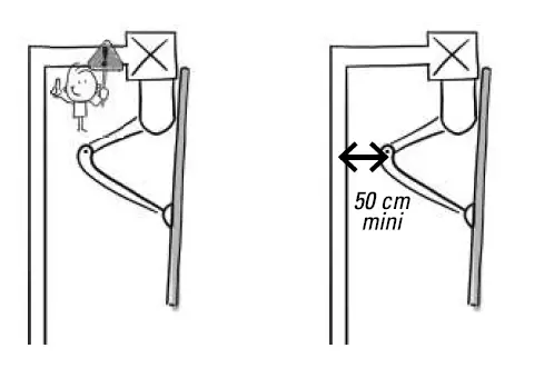
WARNING: Activation of the manual disconnection device may cause uncontrolled movement of the driven part due to mechanical failure or loss of balance. If a fixed control device is installed (keypad, key selector, etc.), it must be installed 1.5 m above the ground, away from moving parts but always within sight of the gate.
- If the gate is to operate in automatic closing mode, or if it is to be opened remotely without a direct view of the gate, photocells must be installed without fail.
- If your gate closes automatically, or if it opens onto the public highway, it may be compulsory to install a flashing light, depending on the regulations in the country where the motorised device is installed.
- It is the installer’s responsibility to ensure that the installation is compliant.
- After installation, make sure that the mechanism is properly adjusted and that the protection system and any manual disconnection devices function properly. Permanently attach the label concerning the manual disconnection device to the operating element of this device.
USING THE MOTORISED SYSTEM
PLEASE NOTE: This appliance may be used by children at least 8 years old and by people with reduced physical, sensory or mental capabilities or without experience or knowledge, if they are properly supervised or instructed in the safe use of the appliance, and if the risks involved have been understood.
- Children should not play with the appliance.
- The user’s cleaning and maintenance must not be carried out by unsupervised children.
- Do not allow children to play with the unit or its controls. Keep remote control units out of the reach of children.
- WARNING: The user must supervise the gate during operation and keep people away until the gate is fully opened or closed. Do not deliberately hinder gate movement.
MAINTENANCE AND UPKEEP OF THE MOTORISED DEVICE
- CAUTION: The motorised device must be disconnected from its power source during cleaning, maintenance and parts replacement.
- Check the installation frequently for poor balancing or signs of wear or damage to cables, springs and mounting. Do not use the appliance if any repairs or adjustments are required. Only original parts should be used to replace or repair the motorised system.
For further information, see section
F – Maintenance
REMOTE CONTROLS
CAUTION: Do not swallow the battery (risk of chemical burns).
- This product contains a button cell battery. If swallowed, the button cell battery can cause severe internal burns in only 2 hours and may cause death. Keep new and used batteries out of the reach of children. If the battery compartment does not close securely, stop using the product and keep it out of the reach of children. If you suspect a battery or other part has been swallowed or inserted into any part of the body, seek medical advice immediately. Do not clean the remote control with abrasive or corrosive substances.
- Just use a soft cloth. Do not allow children to play with the product or its packaging. When replacing batteries, ensure they have the same characteristics as the ones supplied with the product. If the device is not being used for a prolonged period, remove the batteries unless the system is intended for emergency situations. Do not expose the batteries to excessive heat or throw them in a fire.
Potential risks
There are 4 potential risks 3 zones identified opposite: 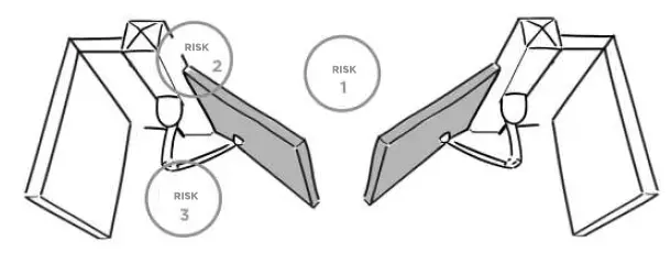
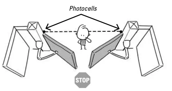
Risk 1 : Shock and crushing
Prevention :
- Obstacle detection by motor.
- Use of photocells.
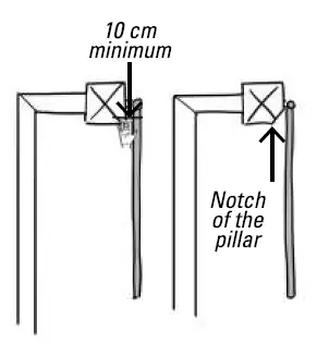
Risk 2: Hand crushing 
Prevention :
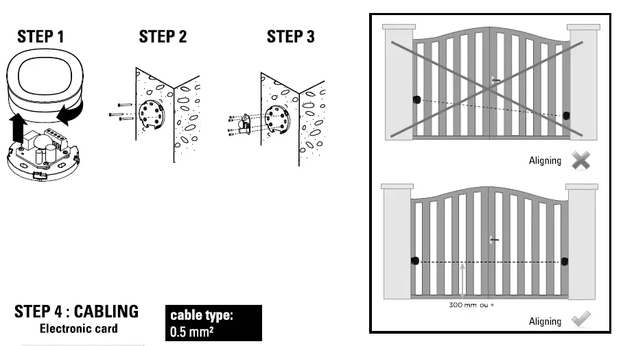
- Leave a minimum distance of 10 cm between the leaf and the pillar/wall.
- Notch the corner of the pillar without weakening it.
Risk 3 : Imprisonment and crushing
Prevention :
- Obstacle detection by the motor.
- Leave a minimum distance of 50 cm between the motor arm and the wall (or other fixed part).
Risk 4 : Crushing of the feet 
Prevention :
To avoid a danger zone for feet, leave a minimum distance of 12 cm or a maximum of 5 mm between the bottom of the leaves and the floor.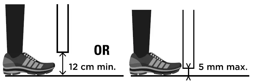
DESCRIPTION
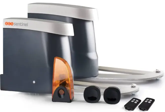
Contents

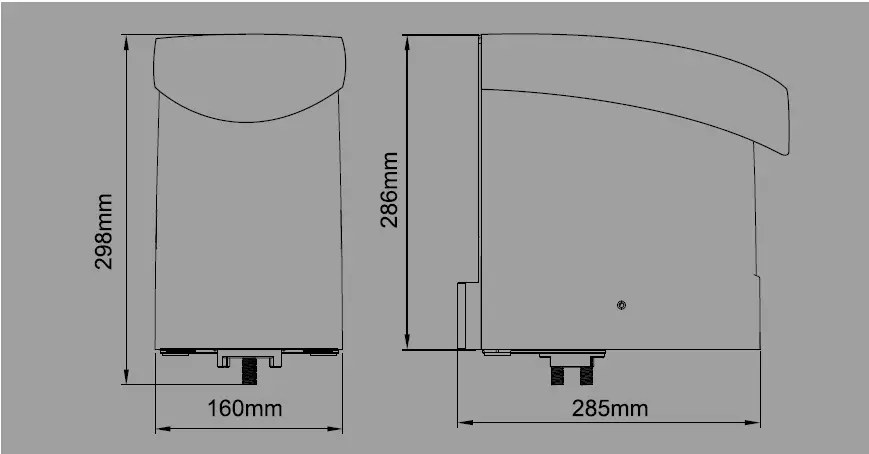
Dimensions
WIRING/ INSTALLING
Standard installation
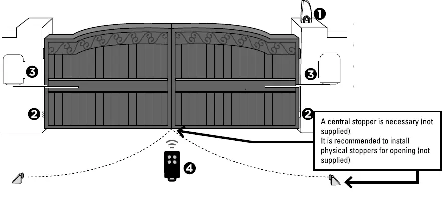
- 24V DC LED blinker with antenna
- Photocells
- 24V DC gate opener
- Remote control
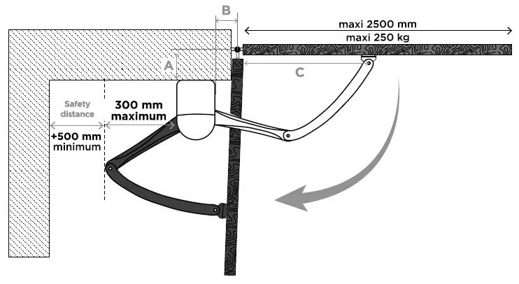
Dimension chart
Comply with the measures shown on the chart for proper installation. Adjust the gate structure to fit it for best automation, if necessary.
Before starting the installation, please make sure that the gate moves freely and that:
- Hinges are properly positioned and greased.
- No any obstacle in the moving area.
- No frictions between two gate leafs or and on the ground while moving.
- Enough space is left when the gate is opening.
- Distance perpendicularly from gate bolt to the front of fixing bracket.
- Distance from the bolt perpendicular to the surface of articulated arm opener.
- Distance between the position of arm fixation and the bolt.
- Installation angle from full closed and full opened position.
Inside opening
Dimension chart
| A(mm) | B(mm) | D | |
| 50 | 50 | 600 | 90°- 95° |
| 50 | 100 | 550 | 90°- 105° |
| 50 | 150 | 500 | 95°- 110° |
| 100 | 50 | 630 | 90°- 95° |
| 100 | 100 | 580 | 90°- 100° |
| 100 | 150 | 530 | 95°- 110° |
| 150 | 50 | 600 | 90°- 95° |
| 150 | 100 | 550 | 90°- 100° |
| 150 | 150 | 500 | 95°-110° |
| 200 | 50 | 600 | 90°-95° |
| 200 | 100 | 550 | 90°-100° |
| 200 | 150 | 500 | 95°-105° |
COTE A:
minimum 50 mm
maximum 200 mm
COTE B:
minimum 50 mm maximum 150 mm
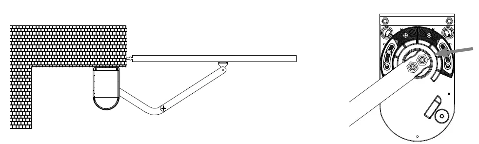
Motor fixing
- Refer to the Dimension Chart to choose the correct dimensions of the motors and position.
- Check if the mounting surface of the brackets to be installed is smooth, vertical and rigid.
- Arrange the cables for power supply cable of the motors.
- Motor installation and setting for mechanical stopper in opened and closed position.
- Remove the upper cover and mechanical stoppers on the bottom of motor.
- Place the gate in the full closed position and fix the LI-shaped fixing plate on the wall.

- Install the motor on the LI-shape with screws (n°8) and corresponding nuts.
- After positioning the front of curved arm on the bottom of motor, position the minor arm on the end of curved arm and mounting bracket with corresponding screws and nuts.

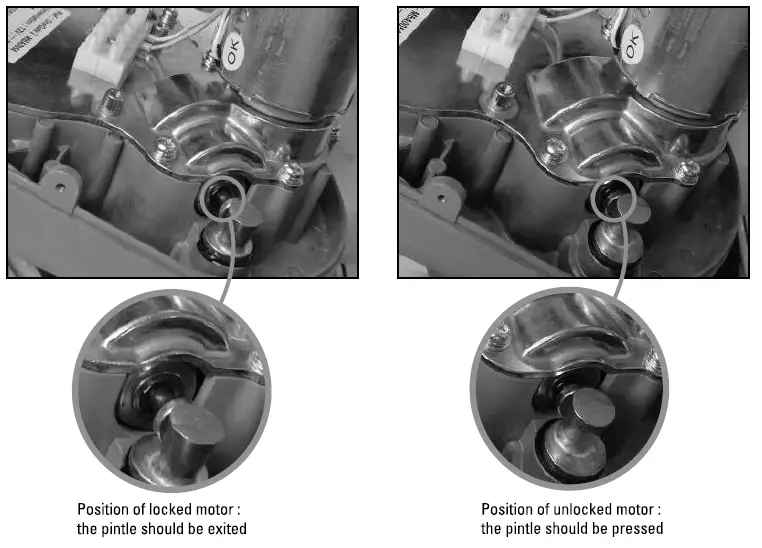
- To unlock the arms refer to paragraph C4
- Closed position adjustment: Once the full closed position is decided, fix the corresponding mechanical stopper in this position.

- Opened position adjustment : Adjust the gate to full opened position and once the position is decided, fix with corresponding mechanical stopper.
- This operation must be carried out a second time to install the second arm
Emergency release
- Insert the release key to the release slot
- Turn the release key clockwise
- Release and move the gate
- At the beginning you may notice that the motors are difficult to release.
- Do not worry, it will disappear with time.
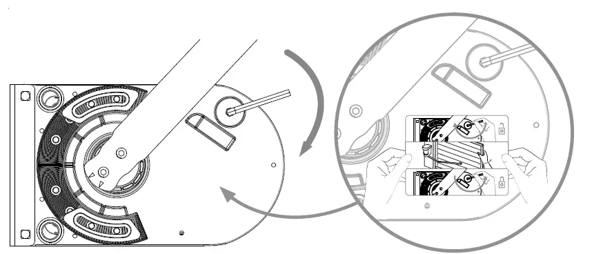
Permanently attach the label for the manual disconnection device to the operating element of th is device.
TIP
Instead of unlocking a motor with arms strength, you can use a battery connecting the white and yellow motor cables one way or the other following the polarity to operate the motors.
The white and yellow cables must be L ! 1 disconnected from the electronic card. 
Wiring diagram


Inside opening
Cas n°1

Cas n°2
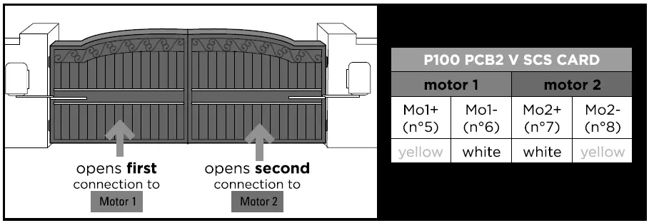
The main and secondary motors can be installed on the right or on the left pillar.
Installing
- Power supply connections
- Please kindly notice that the operation of power connection should be carried out by a qualified electrician with following steps.
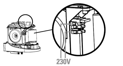
- Make sure that all your connections (motors, blinker, antenna, photocells, lock, etc.) are perfectly made before connecting the 230V power supply to the grey domino.
See diagram (Figure 1 – page 24)
Wire connection secondary motor

Photocells
The photocells are safety devices for control automatic gates. Consist of one transmitter and one receiver based in waterproof covers; it is triggered while breaking the path of the beams. If an obstacle is detected, the gate stops and opens again slightly allowing the obstacle to be released safely.

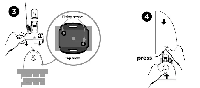
Blinker
Remove any packaging before connecting. 
If you want to improve the operating range of your remote, you can connect the blinker antenna with a RG58 coaxial cable (not supplied). In this case you must disconnect the original antenna and then connect the coaxial copper core to the terminal ANT and the coaxial braided shield to the terminal GND on both antenna and electronic card.
SETTING/USING
Single/double gate setting (dip switch 1)
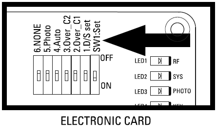
Switch settings: «on» bottom position, «off» top position.
DIP SWITCH 1 D/S set:
- ON= double gate operation
- OFF= single gate operation (connection on 5 and 6)
D2- Dip switch 2 et 3
Switch 2 and 3 are not used.
D3- Gate auto-close adjustment (dip switch 4)
DIP SWITCH 4
«ON»: Active automatic closing in 30 seconds. Simultaneously pressing the two remotes keys![]() (opened or closed gate) will turn OFF the automatic mode (the blinker will flash 3 times as confirmation). Repeat the operation to turn ON the automatic mode (the blinker will flash 3 times as confirmation).
(opened or closed gate) will turn OFF the automatic mode (the blinker will flash 3 times as confirmation). Repeat the operation to turn ON the automatic mode (the blinker will flash 3 times as confirmation).
Note: in case of automatic closing, photocells are required.
«OFF»: Automatic closing OFF (caution it will still be possible to turn ON with the remote)
Photocell adjustment (dip switch 5)
DIP SWITCH 5 :
- ON : Photocells ON. When the photocells detect an obstacle while the gate is closing, the gate stops and opens during 2 seconds.
If the gate auto-close is adjusted, and the photocells detect an obstacle when the gate is totally opened, then the closing time will be reseted. - OFF: Photocells OFF. The photocells will no longer have any influence on gate operation.
Dephasing of the leaves (dip switch 6)
DIP SWITCH 6 :
- ON : Dephasing in closing/ opening of 8 seconds.
- OFF: Dephasing in closing/ opening of 5 seconds.
Slowing down
Operating speeds are not adjustable.
LED indication

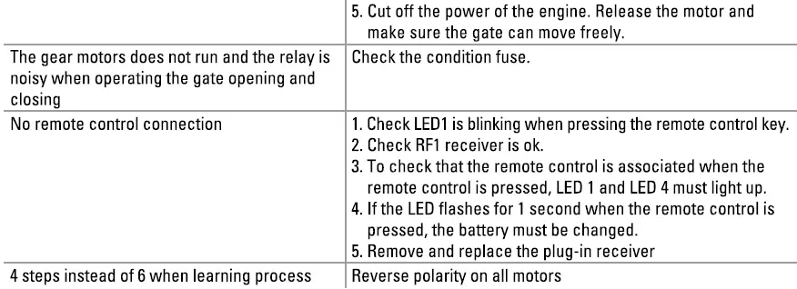
- LED 1 Indicator : radio frequency
LED1 will be on when remote controls are activated. - LED 2 System learning:
LED 2 blinks twice per second during normal operation and once per second during learning. Static LED2 means the learning process can be done over and over again. - LED 3 Photocells:
LED 3 will be on when photocells are not aligned or when there’s an obstacle in between. - LED4 start:
LED 4 will be on if the switch of the transmitter, key selector, or the push button is activated.
Remote controls learning process
- Add the remote controls to the motorization :
- Press the ‘RF-Learn’ button until LED1 lights up.
- Then press the button at the left of the remote control. LED1 flashes twice and remains lit for 10 seconds, then goes out. The remote control has been memorised.
- Deleting remote controls from the motorisation :
- Hold down the RF button until LED1 goes out.
System learning process for double leaf gate
- Switch n°1 must be in the ON position.
- Unlock the motors, position the 2 leaves at mid-travel, then re-lock the motors.
- On the electronic board, hold down the SYS-learn button until LED2 flashes once a second (instead of twice a second or steady), then release.
- Press the button on the left of the remote control.
- The learning process should be as follows:
- The leaf connected to the MOT2 output closes completely. (If it opens, press the left-hand button on the remote control again to interrupt the learning procedure. LED2 remains permanently lit. Reverse the motor polarity and start again from step 1).
- The leaf connected to the MOT1 output closes completely. (If it opens, press left again on the remote control to interrupt the learning procedure. LED2 remains permanently lit. Reverse the motor polarity and start again from step 1 ).
- The leaf connected to output MOT1 reopens completely.
- The leaf connected to output MOT2 reopens fully.
- The leaf connected to the MOT2 output closes completely.
- The leaf connected to output MOT1 closes completely.
After step 5, the system learning process is complete. You can use it with the remote control: 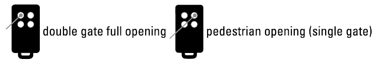
The LED2 light will remain ON until the system learning process is not over. Check the wiring connection and repeat the step.
System learning process for single leaf gate
- Switch No. 1 must be in the OFF position.
- The motor must be connected to the MOTi output.
- Unlock the motor, position the leaf at mid-travel, then re-lock the motor.
- On the electronic board, hold down the SYS-learn button until LED2 flashes once a second (instead of twice a second or steady), then release.
- Press the button on the right of the remote control.
- The learning process should be as follows:
- The leaf closes completely. (If it opens, press the right-hand button on the remote control again to interrupt the learning procedure. LED2 remains permanently lit. Reverse the polarity of the motor and start again from step 3).
- The leaf reopens fully.
- The leaf closes fully.

Obstacle detection
- If an obstacle is detected while the gate is opening: the gate stops.
- If an obstacle is detected while the gate is closing: the gate stops, reopens and closes again.
When the gate reaches the closing stop, it reopens to clear any obstacle.
TECHNICAL FEATURES
Motor
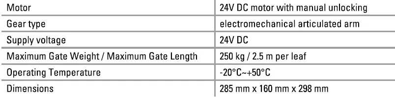
The A-weighted emitted sound pressure level of the motor is equal or less than 70 dB (A).
Blinker

Photocells

Remote controls
| Channels | 4 |
| Frequency – Maximum transmitted power | 433.92 MHz – power< 10 mW |
| Power supply | 1 battery lithium CR2032 included |
| Security | rolling code technology |
MAINTENANCE
Motor
Conduct the following operations at least every 6 months. If in high intensity of use, shorten the period in between.
Disconnect the power supply:
- Clean and lubricate the screws, the pins, and the hinge with grease.
- Check the fastening points are properly tightened.
- Make the wire connection are in good condition.
Connect the power supply:
- Check the power adjustments.
- Check the function of the manual release.
- Check the function of photocells or other safety device.
Remote control 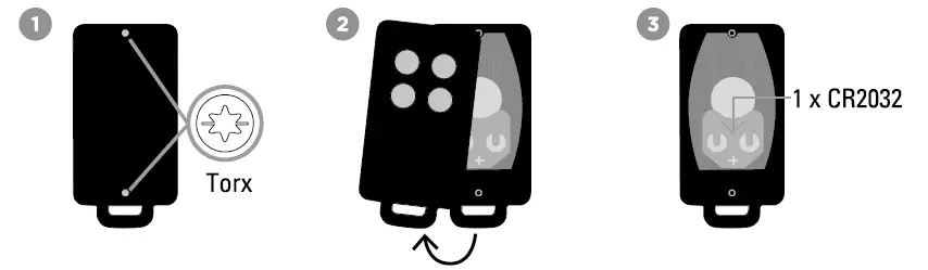
Maintenance advice
| Ensure the correct operation of safety devices (photocells, flashing light, etc.) |
1 x per season |
Clean inside and out with a microfiber |
| Ensure that the manual clutch works properly | Perform a disengagement, open and close your gate completely manually (during the disengagement a hard point can come before manoeuvring manually it remains a normal phenomenon) |
| Check the electronic safe for oxidation, insects or other damage |
1 x per season |
Clean inside and out with a microfiber |
| Sealing of the electronic box | Check silicone seals+ gland | |
| Check the gate | 1 x year | lubrication of hinges |
TECHNICAL ASSISTANCE
Troubleshooting

Tutos

Free online
Any question?
For an individual answer, use our on line chat on our website www.scs-sentinel.com
WARRANTY
- SCS Sentinel grants to this product a longer warranty period, beyond the legal time, as a sign of quality and reliability.
- The invoice will be required as proof of purchase date. Please keep it during the warranty period.
- Carefully keep the barcode and the proof of purchase, that will be necessary to claim warranty.
Are never covered by our warranty:
- Damage resulting from the consequences of a bad installation (bad wiring, reverse polarity … ).
- Damage resulting from improper use of the device (use in contradiction with the manual) or its modification.
- Damage resulting from the consequences of the use of components not from SCS SENTINEL.
- Damage due to lack of maintenance, physical shock.
- Damage due to weather: hail, lightning, strong wind etc ..
- Returns made without a copy of the invoice or receipt.
WARNINGS
Don’t throw batteries or out of order products with the household waste (garbage). The dangerous A A substances that they are likely to include may harm health or the environment. Make your retailer take – back these products or use the selective collect of garbage proposed by your city.
DECLARATION OF CONFORMITY
SCS Sentinel hereby declares that this product is in compliance with the essential requirements and other relevant provisions of Directive 2014/53/EU and Directive 2006/42/EC. The Declaration of Conformity can be found at: www.scs-sentinel.com/downloads

SAFETY INSTRUCTIONS
This manual is an integral part of your product. These instructions are provided for your safety. Read this manual carefully before installing and keep it in a safe place for future reference. Select a suitable location. Make sure you can easily insert screws and wallplugs into the wall. Do not connect your electrical appliance until your equipment is totally installed and controlled. The installation, electric connections and settings must be made using best practices by a specialized and qualified person. Check the product is only used for its intended purpose.
DESCRIPTION
Content/ Dimensions 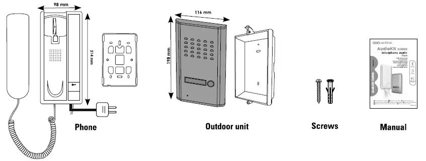
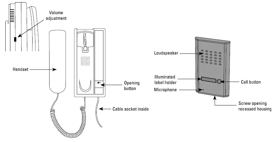
Components
WIRING/ INSTALLING
Wiring diagram

Attaching and connecting the elements
- Attach the outdoor station at a height of 1.5 metres mounted on a flat wall.
- Installing the door station in a porch or covered area is highly recommended, so that it is not directly exposed to sunlight or weather conditions.
- Remove the bottom from the panel, slightly lift the flush-mounted unit then slide off the front panel.
- Connect the outdoor station wire (as shown in the diagram below) and insert the outdoor station onto its support.
- Attach the interior unit at a height of 1.5 metres on a flat wall. First fit the rear plastic support, connect the wires and place the handset on its support.
- Connect the interior unit.
- Perform functional test before finalizing fixing of the elements.
After installing and testing, place a clear silicon seal on the top and sides of the outdoor station (not on the Lil bottom) to avoid any risk of infiltration. 
TECHNICAL FEATURES
Outdoor station 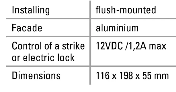
Phone
| Installing | wall-mounted |
| Wiring | 0-50 meters:0.75 mm 2 cable (not supplied) from 51 to 100 meters:1 mm 2 cable (not supplied) |
| Maximum wiring distance | 100 m |
| Used | only indoors |
| Dimensions | 98x214x40mm |
TECHNICAL ASSISTANCE
Any question ?
For an individual answer, use our online chat on our website www.scs-sentinel.com
WARRANTY
- The invoice will be required as of purchase date. Please keep it during the warranty period,
- Carefully keep the barcode and the proof of purchase, that will be necessary to claim warranty.
WARNINGS
- Maintain a minimum distance of 1 0 cm around the device for sufficient ventilation.
- Be sure that the device is not blocked by paper, tablecloth, curtain or other items that would impede airflow.
- Keep matches, candles and flames away from the device.
- Product functionality can be influenced by a strong electromagnetic interference.
- This equipment is intended for private consumer use only.
- The appliance should not be exposed to dripping or splashing water; no objects filled with liquids, such as vases, should be placed near the appliance.
- Do not use in a tropical climate.
- The mains plug is used as disconnect device and shall remain readily operable during intended use.
- The handset must only be used indoors.
- Connect all the parts before switching on the power.
- Do not cause any impact on the elements as their electronics are fragile.
- Do not block the microphone.
- When installing the product, keep the packaging out of reach of children and animals. It is a source of potential danger.
- This appliance is not a toy. It is not designed to be used by children.
- The maximum ambient temperature of the appliance should not exceed 40°C.
- If the power cord or plug is broken, the appliance must be disposed of.
- Disconnect the appliance from the main power supply before service. Do not clean the product with solvent, U4I abrasive or corrosive substances. Only use a soft cloth. Do not spray anything on the appliance.
- Make sure that your appliance is properly maintained and regularly checked in order to detect any sign of
- Don’t throw out of order products with the household waste (garbage). The dangerous substances that they ? are likely to include may harm health or the environment. Make your retailer take back these products or use the selective collect of garbage proposed by your city.

0<30sentinel
110, rue Pierre-Gilles de Gennes 49300 Chalet – France
Documents / Resources
 |
scs sentinel MBA0103 Electric Gate with Opengate 2 Intercom [pdf] Instruction Manual MBA0103 Electric Gate with Opengate 2 Intercom, MBA0103, Electric Gate with Opengate 2 Intercom, Opengate 2 Intercom |


