Satel MLB-400 Conventional Side Line Module
IMPORTANT INFORMATION
The device should be installed by qualified personnel. Prior to installation, please read carefully this manual in order to avoid mistakes that can lead to malfunction or even damage to the equipment. Disconnect power before making any electrical connections. Changes, modifications or repairs not authorized by the manufacturer shall void your rights under the warranty.
The following symbols may be used in this manual:
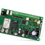
The MLB-400 module is used to connect conventional detectors (DMP-100 / DRP-100 / DCP-100) or manual call points (ROP-110 / ROP-111) to the addressable fire alarm control panel. It is designed to operate in the detection line of the ACSP-402 addressable fire alarm control panel.
Features
- Up to 32 detectors or 10 manual call points are supported.
- Double-sided short-circuit isolator.
- Power from the detection line.
- Possible installation in places where condensation of water vapor occurs.
Installation
Disconnect power before making any electrical connections
The module is designed for indoor installation.
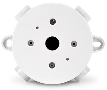
- Make the holes for cables in the enclosure base (Fig. 1).

- Place the enclosure base against the wall or ceiling and mark the location of mounting holes (Fig. 1). If the condensation of water vapor occurs in the place of installation, do not make the holes for screws inside the enclosure.
- Drill the holes for wall plugs (anchors).
- To seal the cable holes, use cable glands (recommended cable gland: PG-16).
- Use wall plugs and screws to secure the enclosure base to the wall. Select wall plugs specifically intended for the mounting surface (different for concrete or brick wall, different for plaster wall, etc.).
- Run the cables inside the enclosure.
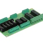
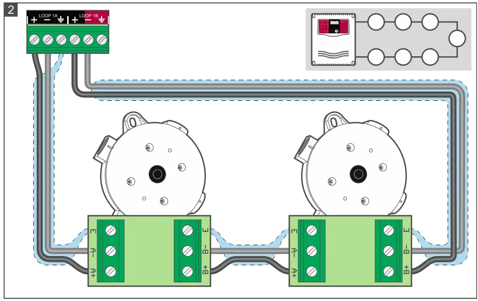
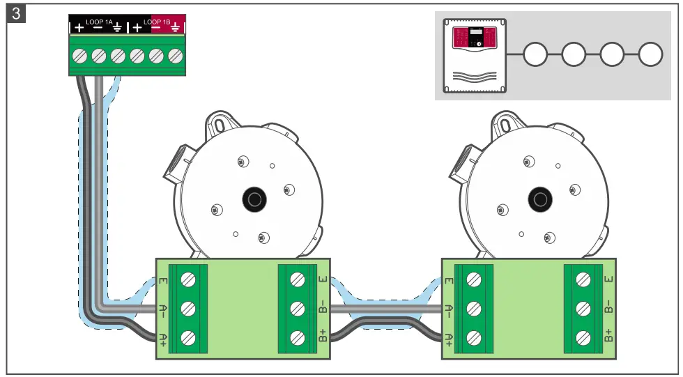
- Connect the detection line wires to the module (Fig. 2 – loop; Fig. 3 – radial circuit). To terminals A+ and A-, connect the wires from the control panel / previous device. Connect the wires to terminals B+ and B- to connect the module to the next device/control panel. For radial circuits, if the module is the last device in the circuit, do not connect the wires to terminals B+ and B- (Fig. 3). Connect the cable shields to the E / terminals.
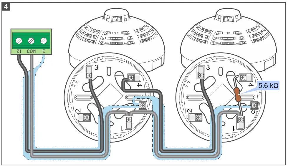
- Connect the conventional devices to the module (Fig. 4 – detectors; Fig. 5 – manual call points). You can connect up to 32 detectors or 10 manual call points. The circuit should be terminated with a 5.6 kΩ resistor (you can screw the resistor to the terminals of the last device in the circuit).
- Do not connect detectors and manual call points simultaneously.
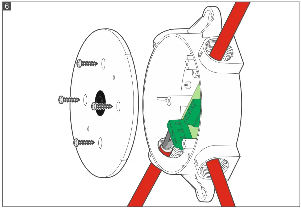
- Replace the cover and lock it with screws (Fig. 6).


Maintenance
The fire alarm system elements require regular maintenance. The periodic checks of the MLB-400 module should be carried out at least every 6 months. In spaces where working conditions are difficult (e.g. dust, an aggressive environment that may cause corrosion, etc.), periodic checks should be carried out more often. As part of maintenance, start a test in the control panel and make sure the module transfers alarm information from connected detectors or manual call points. Please go to the ACSP-402 control panel manuals to find out how to start the test. Start of the test and test activation of devices will be registered in the control panel event log. During the test, make sure the device is in its right place (e.g. it has not been swapped with another device).
Specifications
- Supply voltage …………………………………………………………………………………………..18…26 VDC
- Quiescent current consumption ……………………………………………………………………………..3 mA
- Alarm current consumption………………………………………………………………………………….20 mA
- Operating temperature range…………………………………………………………………….-10°C…+55°C
- Maximum humidity…………………………………………………………………………………………….93±3%
- Dimensions …………………………………………………………………………………..131 x 131 x 38.5 mm
- Weight………………………………………………………………………………………………………………. 153 g
MORE INFO
The MLB-400 conventional side line module conforms to the essential requirements of the
EU Regulations and Directives:
- CPR 305/2011 Regulation of the European Parliament and of the Council of 9 March 2011 laying down harmonized conditions for the marketing of construction products and repealing the Council Directive 89/106/EEC on construction products;
- EMC 2014/30/UE Electromagnetic Compatibility Directive;
- LVD 2014/35/EU Low Voltage Directive.
The CNBOP-PIB Certification Body in Józefów issued the Certificate of Constancy of Performance 1438-CPR-0852 for the construction product MLB-400 conventional sideline module, confirming its compliance with the requirements of EN 54-18:2005 + AC:2007 Input/output devices and EN 54-17:2005 + AC:2007 Short-circuit isolators. The Certificate and the Declaration of Constancy of Performance can be downloaded from the www.satel.pl website.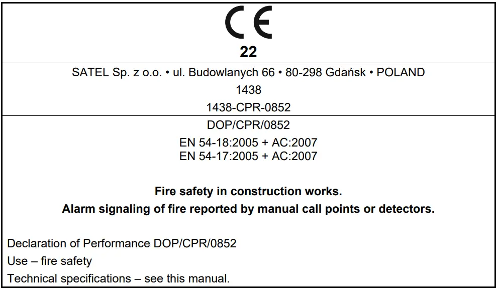
CONTACT INFORMATION
- SATEL sp. z o.o.
- ul. Budowlanych 66
- 80-298 Gdańsk
- POLAND
- tel. +48 58 320 94 00
- www.satel.pl
Documents / Resources
 |
Satel MLB-400 Conventional Side Line Module [pdf] Instruction Manual MLB-400, MLB-400 Conventional Side Line Module, Conventional Side Line Module, Side Line Module, Line Module, Module |