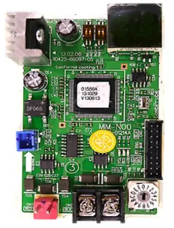
SAMSUNG MIM-N10 Adapter Central Control Interface Module
Safety Information
This installation manual explains how to install an ERV interface module that is connected to a Samsung Ventilator. Please read this manual thoroughly before installing the product. (Please refer to an appropriate installation manual for any optional product installation.)
FOR INSTALLATION
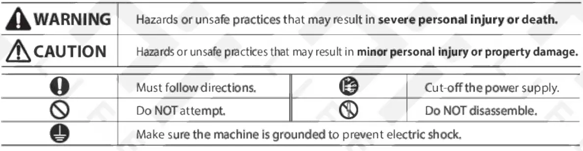
WARNING
Contact a service center for installation.
Failure to do so may result in product malfunction, water leakage, electric shock, or lire.
You must use the supplied wire for installation.
- Failure to do so may result in fire or damage to an ERV interface module.
All electric work should comply with local regulations and installation work carried out by a qualified technician. - Installation by an unqualified technician may result in product malfunction, electric shock, or lire.
Check whether the installation work is performed in accordance with the installation instructions. - Incorrect installation of an ERV interface module may result in electric shock or lire.
FOR INSTALLATION
CAUTION
When connecting a wire, do not tighten it too much.
- Failure to do so may result in breakage of the wire.
Make sure the interface module installation does not cause interference with other electrical appliances, particularly in a hospital etc.
- Failure to do so may result in abnormal operation.
Do not install the product in an area where combustible gas leaks or possible gas leakage is expected.
- Failure to do so may result in fire or explosion.
Do not install the product in conditions where it is exposed to oil, steam etc.
- Use of the product in an area exposed to oil, steam, sulfuric acid gas etc. may result in component damage or product malfunction.
Do not install the product in a place where acid or a lka Ii liquid or special sprays are used.
- Failure to do so may result in electric shock or abnormal operation.
FOR OPERATION
WARNING
- Do not remodel or repair the ERV interface module yourself.
- Failure to do so may result in product malfunction, electric shock, or fire, so contact a se1Vk:e center for repair. When disposing of an ERV interface module, contact a service center.
Do not move or reinstall an installed ERV interface yourself.
- Failure to do so may result in electric shock or lire.
FOR OPERATION
CAUTION
Make sure that water does not permeate inside the ERV interface module.
- Failure to do so may result in electric shock or lire.
Do not connect power cable to the control cable terminal.
- Failure to do so may result in lire.
ERV interface module installation
Products and components
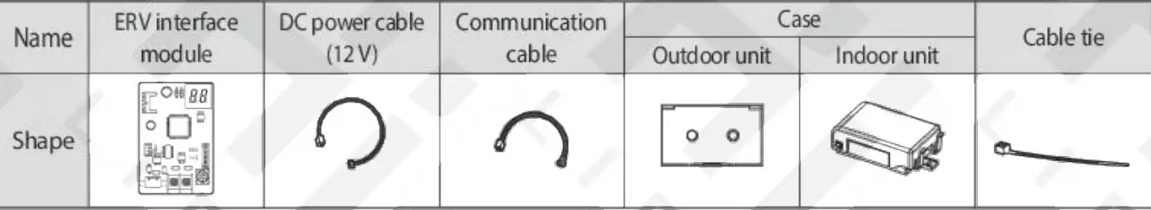
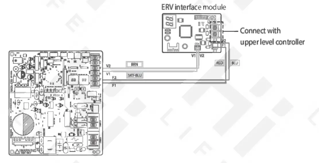
Diagram of connection between an ERV interface module and a Ventilator
- Attach the ERV interface module in the space within the electrical parts of the ventilator.
- Connect the power cable and communication cable of the ERV interface module.
Ifyou use upper level controller (such as DMS, OnOff controller, etc.) with the ERV interface module installed, use of centralized control (installation option 1 of the ERV – SEG5) must beset as “Enable”.
Connecting commercial ERV
- Commercial ERV has screw-type Fl, F2, V1, and V2. Connect DC power cable and communication cable to the terminals by cutting the ends of the cables (on ERV PBA side) and connecting them to the terminals.
- You should separate power cable and communication cable. (Abnormal operation of the product may occur due to the electric problem.)
- ERV interface module (MIM-N10) supports connection between NASA communication upper level controller ↔Non-NASA communication ventilator, Non-NASA communication upper level controller↔NASA communication ventilator, NASA communication upper level controller
- NASA communication ventilator but it does not support communication between Non-NASA communication upper level controller <› Non-NASA communication ventilator.
- You should be aware that power may not be supplied to ERV and interface module if power polarity of V1 and V2 is connected opposite.
Set the address of ERV interface module.
The address for each ERV interface module should be set differently.
Caution
- The cable length between the upper contr oller and the farthest ERV interface module should be within 1000 m.
- You should switch off the power supply before installation.
- The wiring should be installed in accordance with electric wiring regulations and should be placed inside the wall so that users cann ot touch them.
Setting option switch and address switch
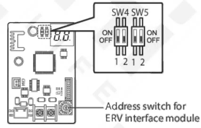
- Swich for setting address: Address switch, set the address within O~F (O~ 15) (Address between each ERV interface module should be set differently)
- Option switch
About setting the main address manually and installation condition
- Connecting NASA communication upper level controller
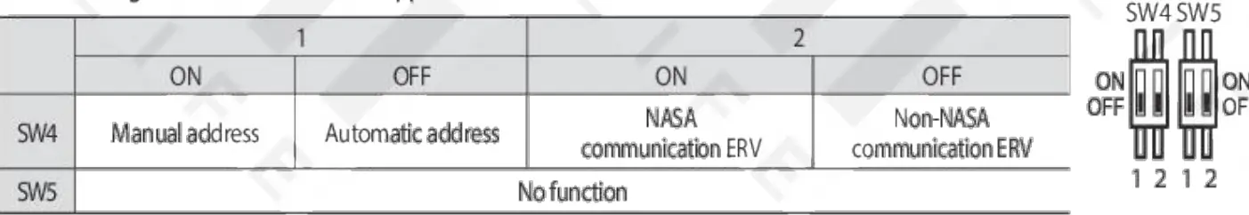
- Automatic address: Address of the interfac e module is assigned randomly.
- Manual address: Address of the interface mod ule is ass igned Di address switch of the ERV interface module.
- Connecting Non-NASA communication upper level controller
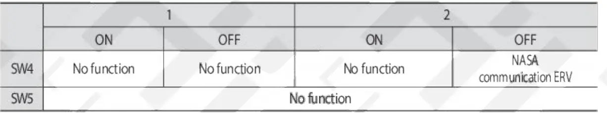
- When connecting Non-NASA communication upper level controller, address of the interface module should be assigned by address switch of the ERV interface module.
- Connection between Non-NASA communication upper level controller~ Non-NASA communication ERV is not supported.
Note
- The default setting of option switch is OFF for both SW4 and SWS.
- When upgrading the program, switch off the power supply of ERV interface module first and set SW4-2 to ON status before proceeding upgrade regardless of the installation condition.
- After completing the upgrade, set the SW4-2 correctly according to installation condition before supplying the power.
When installing 16 Ventilators
OnOff controller

Checking operation
LED Indication
- When resetting the power supply, the ERV interface module will not respond to the upper level communication for up to 10 minutes. If the communication with lower level (e.g.: between ERV interface module and the ventilator) is detected as valid communication, Y-GRN LED will blink. (Please wait until the communication between the ERV interface module and the ventilator becomes normal.)

- When the upper level communication (e.g. Bet ween an OnOff controller and an ERV interface module )is detected as valid communication, the RED LED will blink.
SEGMENT indication
- When initializing power supply
 will be indicated after indicating the program cord.
 - After receiving val id communication more than once,
 will be indicated.
 - When the communication is normal, the MAIN ADDRESS of the ventilator that can be controlled by the ERV interface module is indicated in order.
- When there is no communication between the ventilator and the ERV interface module for more than 3 minutes,
 will be indicated alternately.
 - When there is no communication between an ERV interface module and an upper level controller for more than 3minutes,
 will be indicated alternately.
 - When the ERV interface module tracking is not complete
 will be indicated alternately.
 - When there’s error on the EEPROM of the ERV interface module
 will be indicated alternately.
 - When same address was set to multiple ERV interface modules
 will be indicated alternately.
 - When more than 16ventilators are installed
 will be indicated alternately.
 - When ventilators and indoor units are installed together
 will be indicated alternately.
Notes on interface module installation
- Address of the ventilator can be set between 00–47 ( when manually set) and up to 16 units can be connected to one ERV interface module. For automatic address setting, address will be automatically assigned to each unit between 00~ 1 S.
- Indoor unit and ventilator should not be installed to the same communication line (Fl ,F 2).
- The interface module for an air conditioner is different, make sure MIM-N0l model is connected to an air conditioner.
- Function controller(MCM-A 100) is not compatible.
- lf you have replaced the ERV interface module (due to failure) anytime after setting the centralized control level from the upper level controller, you must set the centralized control level again after replacing the ERV interface module.
- Power of the ERV interface module must be reset after changing the installation condition of the ventilator.
– When changing the number of installed units or address of the ERV
Documents / Resources
 |
SAMSUNG MIM-N10 Adapter Central Control Interface Module [pdf] Installation Guide MIM-N10 Adapter Central Control Interface Module, MIM-N10, Adapter Central Control Interface Module, Central Control Interface Module, Control Interface Module, Interface Module, Module |
 |
SAMSUNG MIM-N10 Adapter Central Control Interface Module [pdf] Installation Guide MIM-N10 Adapter Central Control Interface Module, MIM-N10, Adapter Central Control Interface Module, Central Control Interface Module, Control Interface Module, Interface Module, Module |


