![]()
Ruijie Reyee RG-RAP2260(E)
Access Point
Installation Guide
RG-RAP2260E PoE Plus Access Point
Copyright
Copyright © 2024 Ruijie Networks
All rights are reserved in this document and this statement.
Without the prior written consent of Ruijie Networks, any organization or individual shall not reproduce, extract, back up, modify, or propagate the content of this document in any manner or in any form, or translate it into other languages or use some or all parts of the document for commercial purposes.
![]() , and other Ruijie networks logos are trademarks of Ruijie Networks.
, and other Ruijie networks logos are trademarks of Ruijie Networks.
All other trademarks or registered trademarks mentioned in this document are owned by their respective owners.
Disclaimer
The products, services, or features you purchase are subject to commercial contracts and terms, and some or all of the products, services, or features described in this document may not be available for you to purchase or use.
Except for the agreement in the contract, Ruijie Networks makes no explicit or implicit statements or warranties with respect to the content of this document.
The names, links, descriptions, screenshots, and any other information regarding third-party software mentioned in this document are provided for your reference only. Ruijie Networks does not explicitly or implicitly endorse or recommend the use of any third-party software and does not make any assurances or guarantees concerning the applicability, security, or legality of such software. You should choose and use third-party software based on your business requirements and obtain proper authorization. Ruijie Networks assumes no liability for any risks or damages arising from your use of third-party software.
The content of this document will be updated from time to time due to product version upgrades or other reasons, Ruijie Networks reserves the right to modify the content of the document without any notice or prompt.
This manual is designed merely as a user guide. Ruijie Networks has tried its best to ensure the accuracy and reliability of the content when compiling this manual, but it does not guarantee that the content of the manual is completely free of errors or omissions, and all the information in this manual does not constitute any explicit or implicit warranties.
Preface
Intended Audience
This document is intended for:
- Network engineers
- Technical support and servicing engineers
- Network administrators
Technical Support
- Official Website of Ruijie Reyee: https://reyee.ruijie.com
- Technical Support Website: https://reyee.ruijie.com/en-global/support
- Case Portal: https://www.ruijienetworks.com/support/caseportal
- Community: https://community.ruijienetworks.com
- Technical Support Email: service_rj@ruijienetworks.com
- Online Robot/Live Chat: https://reyee.ruijie.com/en-global/rita
Conventions
- Signs
This document also uses signs to indicate some important points during the operation. The meanings of these signs are as follows:
 Caution
An alert that calls attention to safety instruction that if not understood or followed can result in personal injury.
 Warning
An alert that calls attention to important rules and information that if not understood or followed can result in data loss or equipment damage.
 Note
Note
An alert that calls attention to essential information that if not understood or followed can result in function failure or performance degradation.
 Instruction
An alert that contains additional or supplementary information that if not understood or followed will not lead to serious consequences.
 Specification
An alert that contains a description of product or version support. - Note
This manual provides installation steps, troubleshooting, technical specifications, and usage guidelines for cables and connectors. It is intended for users who want to understand the above and have extensive experience in network deployment and management, and assume that users are familiar with related terms and concepts.
Product Overview
Featuring leading 802.11a/b/g/n/ac/ax and MU-MIMO, Ruijie RG-RAP2260(E) supports 4 spatial streams and delivers up to 800 Mbps at 2.4 GHz and 2400 Mbps at 5 GHz. The overall dual-band performance speeds up to 3200 Mbps per device, totally eliminating Gigabit wireless bottlenecks. RG-RAP2260(E) adopts either local power supply or PoE power supply, and provides two Ethernet ports, making it possible connect a camera or switch device to adapt to challenges in a wide variety of deployment scenarios.
1.1 Technical Specifications
Table 1-1 RG-RAP2260(E) Technical Specifications
| Model | RG-RAP2260(E) |
| RF | Four-stream and dual-band |
| Transmission Protocol | Support concurrent 802.11ax, 802.11ac wave2/wave1, 802.11a/b/g/n |
| Operating Bands | 802.11b/g/n: 2.4 GHz to 2.4835 GHz 802.11a/n/ac/ax: 5.150 GHz to 5.250 GHz, 5.250 GHz to 5.350 GHz, 5.470 GHz to 5.725 GHz, 5.725 GHz to 5.850 GHz (Country-specific) |
| Antenna | Array antenna (2.4 GHz: 3dBi, 5 GHz: 3dBi) |
| Spatial Streams | 2.4 GHz: 4 x 4 MIMO 5 GHz: 4 x 4 MIMO |
| Max Throughput | 2.4 GHz: up to 800 Mbps 5 GHz: up to 2400 Mbps Up to 3200 Mbps per AP |
| Modulation | OFDM: BPSK@6/9Mbps, QPSK@12/18Mbps, 16QAM@24Mbps, 64QAM@48/54Mbps DSSS: DBPSK@1Mbps, DQPSK@2Mbps, and CCK@5.5/11Mbps MIMO-OFDM: BPSK, QPSK, 16QAM , 64QAM, 256QAM and1024QAM OFDMA |
| Receive Sensitivity | 11b: -91dBm(1Mbps), -90dBm(5Mbps), -87dBm(11Mbps) 11a/g: -89dBm(6Mbps), -82dBm(24Mbps), -78dBm(36Mbps), -72dBm(54Mbps) 11n: -85dBm(MCS0), -67dBm(MCS7) 11ac: 20MHz: -85dBm(MCS0), -60dBm(MCS9) 11ac: 40MHz: -82dBm(MCS0), -57dBm(MCS9) 11ac: 80MHz: -79dBm(MCS0), -53dBm(MCS9) 11ax: 80MHz: -79dBm(MCS0), -53dBm(MCS9),-52dBm(MCS11) |
| Transmit Power | ≤100mw(20dBm) (adjustable) |
| Transmit Power Adjustment | 1 dBm |
| Dimensions (W x D x H) | 220 mm x 220 mm x 35 mm (8.7 in. x 8.7 in. x 1.4 in.) (excluding brackets) |
| Weight | ≤ 1.05 kg (excluding brackets) |
| Service Ports | One 10/100/1000BASE-T Ethernet uplink port, one 10/100/1000/2500BASE-T Ethernet uplink |
| port, LAN1/2.5G/PoE port is PoE+-capable | |
| Management Ports | N/A |
| LED | 1 LED (green) |
| Power Supply | Adapter: DC 12 V/2.5 A (optional) PoE: IEEE 802.3at-compliant (PoE+). |
| Power Consumption | < 25.4W |
|
Temperature |
Operating: 0°C to 40°C (32°F to 104°F) |
| Storage: –40°C to 70°C (–40°F to 158°F) | |
|
Humidity |
Operating: 5% to 95% RH (non-condensing) |
| Storage: 5% to 95% RH (non-condensing) | |
| Installation | Ceiling/wall mount |
| Certification | CE |
| MTBF | > 400,000 H |
![]() Weight refers to the weight of host.
Weight refers to the weight of host.
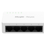
1.2 Product Image
The AP provides two Ethernet ports (LAN1/2.5G/PoE port is PoE+-capable), and one 12V DC power port for an external
power supply. The label is located on the bottom of the device.
Figure 1-1 Appearance of RG-RAP2260(E)

1.3 LED Indicator and Button
| LED Indicator and Button | State | Frequency | Meaning |
| LED Indicator | Off | N/A | The AP is NOT receiving power. |
| Blinking | 0.5Hz | Normal operation, but there is an alarm. | |
| Fast blinking | 10Hz | Possible cases: 1. Restoring the factory default settings 2. Upgrading the firmware 3. Restoring the image file 4. Initializing the device |
|
| Solid green | N/A | Normal operation. | |
|
Reset Button |
Press for less than 2 seconds | Restart the device. | |
| Press for more than 5 seconds | Restore the factory settings. | ||
1.4 Power Sources
The AP can be powered either with a power adapter or through Power over Ethernet (PoE).
![]() The power adapter is customer-supplied.
The power adapter is customer-supplied.
![]() To use a PoE device, make sure that it supports the IEEE 802.3at standard.
To use a PoE device, make sure that it supports the IEEE 802.3at standard.
1.5 Cooling Solution
The AP features a fanless design.
![]() Leave sufficient space surrounding the AP when installing the AP to permit proper airflow for ventilation.
Leave sufficient space surrounding the AP when installing the AP to permit proper airflow for ventilation.
Preparing for Installation
![]() To prevent device damage and physical injury, please read the safety recommendations carefully as described in this chapter.
To prevent device damage and physical injury, please read the safety recommendations carefully as described in this chapter.
![]() Recommendations do not cover all possible hazardous situations.
Recommendations do not cover all possible hazardous situations.
2.1 Installation
The AP must be installed indoors. To ensure normal operation, the installation site must meet the following requirements.
- Install the AP in a well-ventilated environment. If it is installed in a closed room, make sure there is a good cooling system.
- Make sure the site is sturdy enough to support the AP and its accessories.
- Make sure the site has enough space for installing the AP and leave sufficient room around the AP for ventilation.
- Do not expose the AP to high temperature, dust, or harmful gases.
- Do not install the AP in an area prone to fire or explosions.
- Keep the AP away from EMI sources such as large radar stations, radio stations, and substations.
- Do not subject the AP to unstable voltage, vibration, and noises.
- Keep the AP at least 500 meters away from the ocean and do not face it towards the sea breeze.
- The installation site should be free from water including possible flooding, seepage, dripping, or condensation.
- The installation site should be selected according to network planning and communications equipment features, and considerations such as climate, hydrology, geology, earthquake, electrical power, and transportation.
![]() Please follow the correct method described in the installation guide to install and remove the device.
Please follow the correct method described in the installation guide to install and remove the device.
2.2 Movement
- Avoid frequently moving the device.
- Turn off all power supplies and unplug all power cables before you remove the device.
2.3 EMI
- Please observe local regulations and specifications when performing electrical operations. Relevant operators must be qualified.
- Carefully check for any potential hazards in the working area such as damp/wet ground or floors.
- Find the location of the emergency power supply switch in the room before installation. Cut off the power supply first in case of an accident.
- Be sure to make a careful check before shutting down the power supply.
- Do not place the device in a damp/wet location. Do not let any liquid enter the chassis.
- Keep the AP far away from grounding or lightning protection devices for power equipment.
- Keep the AP away from radio stations, radar stations, high-frequency high-current devices, and microwave ovens.
![]() Any nonstandard and inaccurate electrical operation can cause an accident such as fire or electric shock, thus causing severe even fatal damages to humans and devices.
Any nonstandard and inaccurate electrical operation can cause an accident such as fire or electric shock, thus causing severe even fatal damages to humans and devices.
![]() Direct or indirect contact with a wet object (or your finger) on the high voltage and power line can be fatal.
Direct or indirect contact with a wet object (or your finger) on the high voltage and power line can be fatal.
2.4 Ventilation
For proper ventilation, leave sufficient space around the AP.
2.5 Temperature and Humidity
To ensure the normal operation and equipment service life, maintain appropriate temperature and humidity levels in the equipment room. See Table 2-1. Improper room temperature and humidity can cause damage to the device.
- High relative humidity may affect insulation materials, resulting in poor insulation and even electrical leakage.
Sometimes it may lead to changes in the mechanical properties of materials and corrosion of metal parts. - Low relative humidity can dry and shrink insulation sheets and cause static electricity that can damage the circuitry.
- High temperatures greatly reduce device reliability and shorten service life.
Table 2-1 Required Temperature and Humidity for the RG-RAP2260(E)
| Temperature | Relative Humidity |
| 0ºC to 40ºC (32°F to 104°F) | 5% to 95% |
2.6 Cleanness
Dust poses a serious threat to device operation. Dust on the surface of the device can be absorbed onto metal contact points by static electricity causing poor contact. Electrostatic absorption of dust occurs more easily when the relative humidity is low, and might shorten the equipment service life and cause communication failures. Table 2-2 shows the maximum concentration and diameter of dust allowed in the equipment room.
Table 2-2
| Maximum diameter (μm) | 0.5 | 1 | 3 | 5 |
| Maximum concentration (Particles/m3) | 1.4×10⁷ | 7×10⁵ | 2.4×10⁵ | 1.3×10⁵ |
The amount of salt, acids and sulfides in the air are also strictly limited for the equipment room. These substances can accelerate metal corrosion and aging of some parts. Table 2-3 describes the limits of some hazardous gases such as SO2, H2S, NO2 and Cl2 in the equipment room.
Table 2-3
| Gas | Average (mg/m3) | Maximum (mg/m3) |
| SO2 | 0.2 | 1.5 |
| H2S | 0.006 | 0.03 |
| NO2 | 0.04 | 0.15 |
| NH3 | 0.05 | 0.15 |
| Cl2 | 0.01 | 0.3 |
2.7 Power Supply
- DC power adapter:
Input voltage: 12V
Rated current: 2.5A - PoE+ injector: IEEE 802.3at compliant
Technical Specifications of the DC Connector
| Inner Diameter | Outer Diameter | Insertion Depth | Conductor Impedance | Voltage-endu rance Impedance | Voltage-endu rance (Insulator and Conductor) | Polarity |
| 2.10+/-0.05mm | 5.50+/-0.05mm | 9mm | 5Ω | 100MΩ | 1000V | Inner pole: positive Outer pole: negative |
![]() The DC input power should be greater than the power actually consumed by the system.
The DC input power should be greater than the power actually consumed by the system.
![]() Use DC power adapters with specifications recommended by Ruijie.
Use DC power adapters with specifications recommended by Ruijie.
![]() Please use Ruijie certified PoE injectors.
Please use Ruijie certified PoE injectors.
![]() Warning:802.3af or non-standard PoE adapter may cause unknown issues. Please use Ruijie PoE+ switch or 802.3at PoE adapter as power supplier
Warning:802.3af or non-standard PoE adapter may cause unknown issues. Please use Ruijie PoE+ switch or 802.3at PoE adapter as power supplier
2.8 Installation Tools
| Common Tools | Phillips (crosshead) screwdriver, copper and fiber cables, bolts, diagonal pliers, cable ties |
| Special Tools | Wire stripper, crimping pliers, RJ-45 crimping pliers, punch down tool |
| Meter | Multimeter, bit error rate tester (BERT) |
![]() The tools listed above are customer supplied.
The tools listed above are customer supplied.
2.9 Unpacking the Access Point
Package Contents
| Items | Verify that all parts are installed and debugged. Screws Mounting brackets Product quick installation guide Packing list |
![]() The above listed items are for general situations, and contents may vary in the actual shipment. The purchasing order shall prevail in any case. Please check each item carefully according to the packing list or purchasing order. If any item is damaged or missing, notify your sales representative.
The above listed items are for general situations, and contents may vary in the actual shipment. The purchasing order shall prevail in any case. Please check each item carefully according to the packing list or purchasing order. If any item is damaged or missing, notify your sales representative.
Installing the Access Point
The RG-RAP2260(E) series must be fixed and installed indoors.
![]() Before installing the AP, make sure you have carefully read the requirements described in Chapter 2.
Before installing the AP, make sure you have carefully read the requirements described in Chapter 2.
3.1 Installation Flowchart
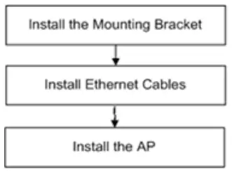
3.2 Before You Begin
Before installing the AP, verify that:
- The installation site provides sufficient ventilation for the AP.
- The installation site meets temperature and humidity requirements.
- The installation site is equipped with a proper power supply.
- Network cables are in place.
- The installation site meets all described requirements.
- The custom AP meets customer requirements.
3.3 Precautions
To avoid damage to the AP, observe the following safety precautions:
- Do not power on the device during installation.
- Install the device in a well-ventilated location.
- Do not subject the device to high temperatures.
- Keep away from high voltage cables.
- Install the device indoors.
- Do not expose the device in a thunderstorm or strong electric field.
- Keep the device clean and dust-free.
- Disconnect the device before cleaning it.
- Do not wipe the device with a damp cloth.
- Do not wash the device with liquid.
- Do not open the enclosure when the AP is working.
- Fasten the device tightly.
3.4 Installing the Access Point
![]() Please install the AP in the method with a larger antenna coverage area.
Please install the AP in the method with a larger antenna coverage area.
![]() The antenna coverage area of ceiling-mounting is larger than that of wall-mounting indoors. Please select the former method.
The antenna coverage area of ceiling-mounting is larger than that of wall-mounting indoors. Please select the former method.
![]() The installation process below is just for reference. The actual product prevails.
The installation process below is just for reference. The actual product prevails.
- Ceiling Mount
1. Attach the mounting bracket on the ceiling or wall, as shown in Figure 3-1.
Figure 3-1 Attaching the Mounting Bracket on the Ceiling/Wall

2. Connect the Ethernet cable to the LAN1 port. See Figure 3-2.
Figure 3-2 Connecting the Ethernet Cable to the LAN1 Port

3. Align the square feet on the rear of the AP over the mounting holes on the bracket. Slide the AP into the holes until it clicks into place, as shown in Figure 3-3.
Figure 3-3 Fastening the AP

![]() Install the Ethernet cables before mounting the AP on the bracket.
Install the Ethernet cables before mounting the AP on the bracket.
![]() The AP can be installed in any of four directions on the mounting bracket depending on how you route the Ethernet cable.
The AP can be installed in any of four directions on the mounting bracket depending on how you route the Ethernet cable.
![]() The square feet should fit easily into the mounting slots. Do not forcibly push the AP into the slots.
The square feet should fit easily into the mounting slots. Do not forcibly push the AP into the slots.
![]() After installation, verify that the AP is securely fastened.
After installation, verify that the AP is securely fastened.
3.5 Removing the Access Point
Hold the AP in your hands and push it upward and away from the bracket in the arrow direction, as shown in Figure 3-1.
3.6 Connecting Cables
Connect the UTP/STP to the LAN1 port on the AP. See Appendix A for the supported wiring for twisted pairs.
![]() Avoid bending the cable in a small radius close to the connector.
Avoid bending the cable in a small radius close to the connector.
![]() Ruijie recommends that you do not use Ethernet cables with protective sleeves as they could make installation of Ethernet cables more difficult.
Ruijie recommends that you do not use Ethernet cables with protective sleeves as they could make installation of Ethernet cables more difficult.
3.7 Bundling Cables
Precautions
- Make sure the cable bundles are neat and orderly.
- Bend twisted pairs naturally or in a large radius close to the connector.
- Do not over tighten a cable bundle as it may reduce cable life and performance.
Bundling Steps
- Bundle the drop UTP/STP cables and route them to the LAN1/2.5G/PoE port.
- Attach the cables in the cable tray of the rack.
- Extend the cables under the AP and run in a straight line.
3.8 Checking after Installation
Checking the Cabinet
- Make sure the external power supply matches the patch panel specifications for the cabinet.
- After installation, make sure that the front and rear cabinet doors easily close.
- Make sure the cabinet is stable and level.
- Make sure the device and all cables are securely fastened in the rack.
Checking Cable Connection
- Make sure the UTP/STP cable matches the interface type.
- Make sure cables are properly bundled.
Checking the Power Supply
- Make sure all power cables are properly connected and safe.
- Make sure the AP is operational after powering on.
System Debugging
4.1 Setting up a Debugging Environment
Use a power adapter or PoE to power the AP.
Setting up the Environment
- Verify that the AP is properly connected to the power source.
- Connect the AP to a wireless controller through a twisted pair cable.
- When the AP is connected to a PC for debugging, verify that the PC and PoE switch are properly grounded.
4.2 Powering up the AP
4.2.1 Checking before power-up
- Verify that the power supply is properly connected.
- Verify that the input voltage matches the specification of the AP.
4.2.2 Checking after power-up (recommended)
After powering up, it is recommended that you check the following to ensure normal operation of the AP.
- Check if any message is displayed on the Web-based configuration interface for the wireless controller.
- Check if the LED works normally.
Monitoring and Maintenance
5.1 Monitoring
LED
You can observe the LED to monitor the AP in operation.
5.1.1 Hardware Maintenance
If the hardware is faulty, please contact our Technical Assistance Center (TAC) for help.
Troubleshooting
6.1 Troubleshooting Flowchart
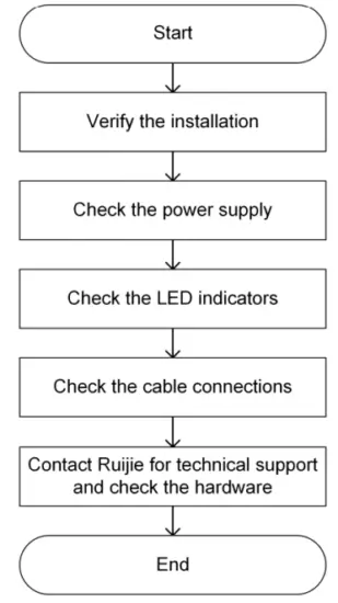
6.2 Troubleshooting
LED does not light up after the AP is powered on
- If you use PoE power supply, verify that the power source is IEEE 802.11at compliant; then verify that the cable is properly connected.
- If you use a power adapter, verify that the power adapter is connected to an active power outlet; then verify that the power adapter works properly.
Ethernet port is not working after the Ethernet port is connected
Verify that the device at the other end of the Ethernet cable is working properly. And then verify that the Ethernet cable is capable of providing the required data rate and is properly connected.
Wireless client cannot find the AP
- First, follow the two steps above.
- Verify that the AP is correctly configured.
- Adjust the angle of the antennas.
- Move the client device to adjust the distance between the client and the AP.
Appendix A Connectors and Media
1000BASE-T/100BASE-TX/10BASE-T
The 1000BASE-T/100BASE-TX/10BASE-T is a 10/100/1000 Mbps auto-negotiation port that supports auto MDI/MDIX.
Compliant with IEEE 802.3ab, 1000BASE-T requires Category 5e 100-ohm UTP or STP (STP is recommended) with a maximum distance of 100 meters (328 feet).
1000BASE-T requires all four pairs of wires be connected for data transmission, as shown in Figure A-1.
Figure A-1 1000BASE-T Connection

10BASE-T uses Category 3, 4, 5 100-ohm UTP/STP and 1000BASE-T uses Category 5 100-ohm UTP/STP for connections. Both support a maximum length of 100 meters. Table A-1 shows 100BASE-TX/10BASE-T pin assignments.
Table A-1 100BASE-TX/10BASE-T Pin Assignments
| Pin | Socket | Plug |
| 1 | Input Receive Data+ | Output Transmit Data+ |
| 2 | Input Receive Data- | Output Transmit Data- |
| 3 | Output Transmit Data+ | Input Receive Data+ |
| 6 | Output Transmit Data- | Input Receive Data- |
| 4,5,7,8 | Not used | Not used |
Figure A-2 shows wiring of straight-through and crossover cables for 100BASE-TX/10BASE-T.
Figure A-2 100BASE-TX/10BASE-T Connection

![]() Document Version: V1.3
Document Version: V1.3
Date: July 22, 2024
Copyright © 2024 Ruijie Networks
Documents / Resources
 |
Ruijie RG-RAP2260E PoE Plus Access Point [pdf] Installation Guide RG-RAP2260E, RG-RAP2260E PoE Plus Access Point, PoE Plus Access Point, Access Point, Point |