ROCKWELL AUTOMATION 1756-OF8K ControlLogix Analog I O Modules
Product Information
Specifications
- Catalog Numbers: 1756-IF4FXOF2F, 1756-IF4FXOF2FK, 1756-IF16, 1756-IF16K, 1756-IF8, 1756-IF8K, 1756-OF4, 1756-OF4K, 1756-OF8, 1756-OF8K
Installation Requirements
- Ensure to read all provided documents before installation, configuration, or maintenance.
Environment and Enclosure
- This equipment is suitable for use in a Pollution Degree 2 industrial environment and overvoltage Category II applications.
- It can be used at altitudes up to 2000 m (6562 ft) without derating.
- Not intended for residential environments.
Product Usage Instructions
Install the Module
- Key the removable terminal block to the module.
- Connect the wiring as per the provided wiring diagram.
- Assemble the RTB housing.
- Install the removable terminal block into the module.
Removable Terminal Blocks (RTB) Ratings
- Refer to the provided documentation for ratings of the removable terminal blocks.
Additional Resources
- For additional resources and support, refer to the documentation provided with the product.
FAQ
What should I do if I encounter issues during installation?
If you encounter any issues during installation, refer to the troubleshooting section in the user manual or contact customer support for assistance.
Can the product be used in residential environments?
No, this product is not intended for use in residential environments as it is designed for industrial applications.
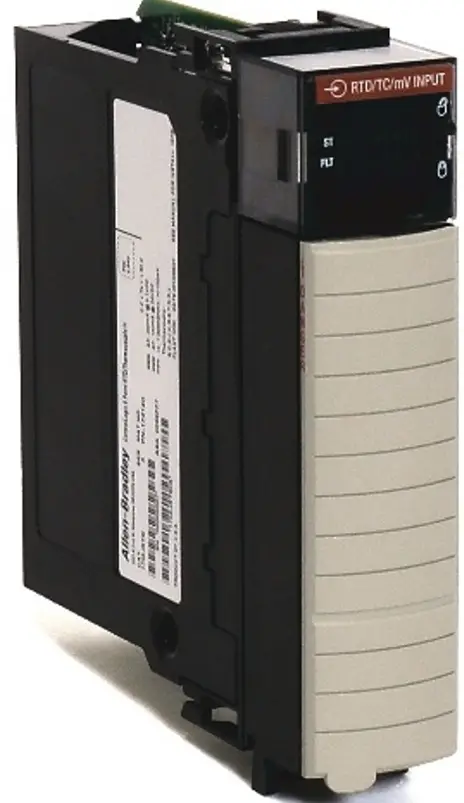
1756 ControlLogix Analog I/O Modules
- Catalog Numbers 1756-IF4FXOF2F, 1756-IF4FXOF2FK, 1756-IF16, 1756-IF16K, 1756-IF8, 1756-IF8K, 1756-OF4, 1756-OF4K, 1756-OF8, 1756-OF8K
- ControlLogix® analog I/O modules are interface modules that convert analog signals to digital values for inputs and convert digital values to analog signals for outputs.
- Controllers can then use these signals for control purposes. By using the producer/consumer network model, analog I/O modules can produce information when needed while providing additional system functions.
Summary of Changes
These updated installation instructions include new and revised content as shown in this table.
- ATTENTION: Read this document and the documents listed in the Additional Resources section about the installation, configuration, and operation of this equipment before you install, configure, operate, or maintain this product.
- Users are required to familiarize themselves with installation and wiring instructions in addition to requirements of all applicable codes, laws, and standards.
- Activities including installation, adjustments, putting into service, use, assembly, disassembly, and maintenance are required to be carried out by suitably trained personnel under the applicable code of practice.
- If this equipment is used in a manner not specified by the manufacturer, the protection provided by the equipment may be impaired.
- ATTENTION: Read this document and the documents listed in the Additional Resources section about the installation, configuration, and operation of this equipment before you install, configure, operate, or maintain this product.
- Users are required to familiarize themselves with installation and wiring instructions in addition to requirements of all applicable codes, laws, and standards.
- Installation, adjustments, putting into service, use, assembly, disassembly, and maintenance must be carried out by suitably trained personnel under the applicable code of practice.
- If this equipment is used in a manner not specified by the manufacturer, the protection that is provided by the equipment may be impaired.
- This equipment is certified for use only within the surrounding air temperature range of 0…60 °C (32…140 °F). The equipment must not be used outside of this range.
- Use only a soft dry anti-static cloth to wipe down equipment. Do not use any cleaning agents.
- In case of malfunction or damage, no attempts at repair should be made. The module should be returned to the manufacturer for repair. Do not dismantle the module.
- IMPORTANT Any illustrations, charts, sample programs, and layout examples shown in this publication are intended solely for example.
- Since many variables and requirements are associated with any particular installation, Rockwell Automation does not assume responsibility or liability for actual use based on the examples shown in this publication.
Environment and Enclosure
- ATTENTION: This equipment is intended for use in a Pollution Degree 2 industrial environment, in overvoltage Category II applications (as defined in EN/IEC 60664-1), at altitudes up to 2000 m (6562 ft) without derating.
- This equipment is not intended for use in residential environments and may not provide adequate protection to radio communication services in such environments.
- This equipment is supplied as open-type equipment for indoor use. It must be mounted within an enclosure that is suitably designed for those specific environmental conditions that will be present and appropriately designed to prevent personal injury resulting from accessibility to live parts. The enclosure must have suitable flame-retardant properties to prevent or minimize the spread of flame, complying with a flame spread rating of 5VA, or be approved for the application if non-metallic.
- The interior of the enclosure must be accessible only by the use of a tool.
- Subsequent sections of this publication may contain additional information regarding specific enclosure-type ratings that are required to comply with certain product safety certifications.
In addition to this publication, see the following:
- Industrial Automation Wiring and Grounding Guidelines, publication 1770-4.1, for additional installation requirements.
- NEMA Standard 250 and EN/IEC 60529, as applicable, for explanations of the degrees of protection provided by the enclosure.
Prevent Electrostatic Discharge
- ATTENTION: This equipment is sensitive to electrostatic discharge, which can cause internal damage and affect normal operation.
Follow these guidelines when you handle this equipment:
- Touch a grounded object to discharge potential static.
- Wear an approved grounding wrist strap.
- Do not touch connectors or pins on component boards.
- Do not touch circuit components inside the equipment.
- Use a static-safe workstation, if available.
- Store the equipment in appropriate static-safe packaging when not in use.
Removal and Insertion Under Power (RIUP)
- WARNING: When you insert or remove the module while backplane power is on, an electric arc can occur. This could cause an explosion in hazardous location installations.
- Be sure that power is removed or the area is nonhazardous before proceeding. Repeated electric arcing causes excessive wear to contacts on both the module and its mating connector.
- Worn contacts can create electrical resistance that can affect module operation.
Removable Terminal Blocks (RTB)
- WARNING: When you connect or disconnect the removable terminal block (RTB) with field-side power applied, an electric arc can occur. This could cause an explosion in hazardous location installations.
- Be sure that power is removed or the area is nonhazardous before proceeding.
Electrical Safety Considerations
- ATTENTION: Power to the 1756-IF4FXOF2F, 1756-IF8, and 1756-IF16 must be supplied with a source compliant with the following:
- Isolation from Mains power via an approved isolating transformer constructed with reinforced insulation.
- If multiple power sources are used, do not exceed the specified isolation voltage.
- When using the 1756-TBCH, do not wire more than two 0.33…1.3 mm2 (22…16 AWG) conductors on any single terminal. Use only the same size wires with no intermixing of solid and stranded wire types.
- When using the 1756-TBS6H, do not wire more than 1 conductor on any single terminal. Use only the same size wires with no intermixing of solid and stranded wires.
- Wire conductor and insulation ratings shall support a minimum temperature rating of 105 °C (185 °F).
North American Hazardous Location Approval
- The following information applies when operating this equipment in hazardous locations.
- Products marked “CL I, DIV 2, GP A, B, C, D” are suitable for use in Class I Division 2 Groups A, B, C, D, Hazardous Locations and nonhazardous locations only.
- Each product is supplied with markings on the rating nameplate indicating the hazardous location temperature code.
- When combining products within a system, the most adverse temperature code (lowest “T” number) may be used to help determine the overall temperature code of the system.
- Combinations of equipment in your system are subject to investigation by the local Authority Having Jurisdiction at the time of installation.
WARNING: Explosion Hazard
- Do not disconnect equipment unless power has been removed or the area is known to be non-hazardous.
- Do not disconnect connections to this equipment unless power has been removed or the area is known to be non-hazardous.
- Secure any external connections that mate to this equipment by using screws, sliding latches, threaded connectors, or other means provided with this product.
- Substitution of components may impair suitability for Class I, Division 2.
- If this product contains batteries, they must only be changed in an area known to be nonhazardous.
UK and European Hazardous Location Approval
The following applies to products marked,![]() II 3 G. Such modules:
II 3 G. Such modules:
- Are Equipment Group II, Equipment Category 3, and comply with the Essential Health and Safety Requirements relating to the design and construction of such equipment given in Annex II to EU Directive 2014/34/EU and Schedule 1 of the UKEX Regulation 2016 No. 1107. See the UKEX and EU Declaration of Conformity at rok. auto/certifications for details.
- The type of protection is <Ex ec IIC T4 Gc> Equipment protection by increased safety “e”.
- Equipment protection by increased safety “e”, reference certificate number UL 22 ATEX 2772X and UL22UKEX2499X.
- Are intended for use in areas in which explosive atmospheres caused by gases, vapors, mists, or air are unlikely to occur, or are likely to occur only infrequently and for short periods.
- Such locations correspond to Zone 2 classification according to UKEX Regulation 2016 No. 1107 and ATEX directive 2014/34/EU.
IEC Hazardous Location Approval
- The following applies to products with IECEx certification. Such modules.
- Are intended for use in areas in which explosive atmospheres caused by gases, vapors, mists, or air are unlikely to occur, or are likely to occur only infrequently and for short periods. Such locations correspond to Zone 2 classification.
- The type of protection is <Ex ec IIC T4 Gc>.
- IECEx certificate number IECEx UL 22.0039X.
Special Conditions for Safe Use
WARNING:
- This equipment is not resistant to sunlight or other sources of UV radiation.
- This equipment shall be mounted in an ATEX/IECEx Zone 2 certified enclosure with a minimum ingress protection rating of at least IP54 (under EN/IEC 60079-0) and used in an environment of not more than Pollution Degree 2 (as defined in EN/IEC 60664-1) when applied in Zone 2 environments. The enclosure must be accessible only by the use of a tool.
- This equipment shall be used within its specified ratings defined by Rockwell Automation.
- Provision shall be made to prevent the rated voltage from being exceeded by transient disturbances of more than 140% of the peak rated voltage when applied in Zone 2 environments.
- The instructions in the user manual shall be observed.
- Secure any external connections that mate to this equipment by using screws, sliding latches, threaded connectors, or other means provided with this product.
- Do not disconnect equipment unless power has been removed or the area is known to be non-hazardous.
Installation Requirements
Before you install the module, you must complete the following steps.
- Install a 1756 ControlLogix chassis.
- Install a 1756 ControlLogix power supply.
Install the Module
- You can install or remove a module while chassis power is applied.
- ATTENTION: The module is designed to support removal and insertion under power (RIUP). However, when you remove or insert a removable terminal block (RTB) with field-side power applied, unintended machine motion or loss of process control can occur. Exercise extreme caution when using this feature.
- Slide the module into the slot in the chassis until the locking tabs click.
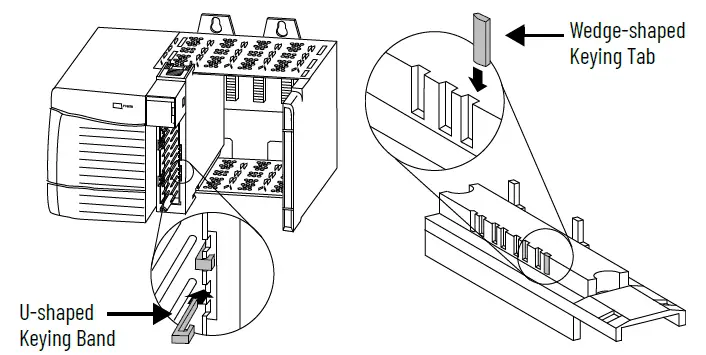
Key the Removable Terminal Block
Key the RTB to help prevent inadvertently connecting the incorrect RTB to your module.
- Push the U-shaped band onto the module until it snaps into place.
- Insert wedge-shaped tabs into positions on the RTB that correspond to unkeyed module positions on the module until they stop.
Connect the Wiring
- You can use an RTB or a Bulletin 1492 pre-wired Interface Module (IFM) to connect wiring to your module. An IFM has been pre-wired before you received it.
- If you are using an RTB, connect wiring as directed in the following steps. We recommend that you use a Belden 8761 cable to wire the RTB. The RTB terminations can accommodate 0.33…2.1 mm2 (22…14 AWG) shielded wire.
- Before wiring the RTB, you must connect ground wiring.
- WARNING: If you connect or disconnect wiring while the field-side power is on, an electric arc can occur. This could cause an explosion in hazardous location installations. Be sure that power is removed or the area is nonhazardous before proceeding.
- ATTENTION: If multiple power sources are used, do not exceed the specified isolation voltage.
- ATTENTION: When using catalog number 1756-TBNH, do not wire more than two 0.33…1.3 mm2 (22…16 AWG) conductors on any terminal. Use only the same size wires with no intermixing of solid and stranded wire types.
- When using the 1756-TBCH, 1756-TBS6H, or 1756-TBSH, do not wire more than one 0.33…2.1 mm2 (22…14 AWG) conductor on any terminal.
- ATTENTION: The ControlLogix system has been agency-certified using only the ControlLogix RTBs (1756-TBCH, 1756-TBNH, 1756-TBS6H. and 1756-TBSH).
- Any application that requires agency certification of the ControlLogix system using other wiring termination methods may require application-specific approval by the certifying agency.
Connect the Grounded End of the Cable
Before wiring the RTB, you must connect the ground wiring.
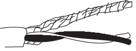
- Remove a length of cable jacket from the Belden cable.
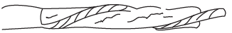
- Pull the foil shield and bare drain wire from the insulated wire.
- Twist the foil shield and drain wire together to form one strand.
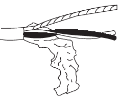
- Attach the ground lug and apply heat shrink tubing to the exit area.
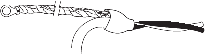
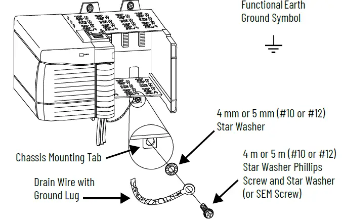
- Connect the drain wire to a chassis mounting tab.
- Use any chassis mounting tab that is designated as a functional signal ground. The functional earth ground symbol appears near the tab.
- Use any chassis mounting tab that is designated as a functional signal ground. The functional earth ground symbol appears near the tab.
- When the drain wire is grounded, connect the insulated wires to the field side.
Connect the Ungrounded End of the Cable
- Cut the foil shield and drain wire back to the cable casing and apply shrink wrap.
- Connect the insulated wires to the RTB.
Wire a Cage Clamp-style RTB – Catalog Number 1756-TBCH
- Insert the wire into the terminal.
- Turn the screw clockwise to close the terminal on the wire.
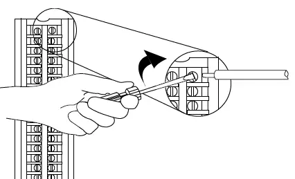
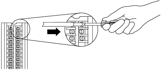
Wire a Spring Clamp – Catalog Number 1756-TBS6H
- Insert the screwdriver into the outer hole of the RTB.
- Insert the wire into the open terminal and remove the screwdriver.
Recommendations for Wiring Your RTB
- We recommend you follow these guidelines when wiring your RTB.
- Begin wiring the RTB at the bottom terminals and move up.
- Use a tie to secure the wires in the strain relief (bottom) area of the RTB.
- Order and use an extended-depth housing (catalog number 1756-TBE) for applications that require heavy gauge wiring.
Assemble the RTB Housing
Removable housing covers the wired RTB to protect wiring connections when the RTB is seated on the module.
- Align the grooves at the bottom of each side of the housing with the side edges of the RTB.
- Slide the RTB into the housing until it snaps into place.
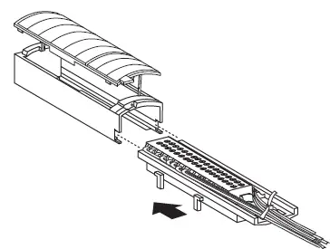
IMPORTANT If additional wire routing space is required for your application, use the extended-depth housing, catalog number 1756-TBE.
Install the Removable Terminal Block
- Before installing the RTB, verify the following.
- Field-side wiring of the RTB is complete.
- The RTB housing is snapped into place on the RTB.
- The RTB housing door is closed.
- The locking tab at the top of the module is unlocked.
- WARNING: When you connect or disconnect the removable terminal block (RTB) with field-side power applied, an electric arc can occur.
- This could cause an explosion in hazardous location installations. Be sure that power is removed or the area is nonhazardous before proceeding.
Follow these steps to install the RTB onto the module to connect the wiring:
- Align the top, bottom, and left side guides of the RTB with the guides on the module.
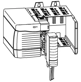
- Press quickly and evenly to seat the RTB on the module until the latches snap into place.
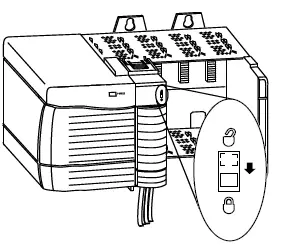
- Slide the locking tab down to lock the RTB onto the module.
Removable Terminal Blocks (RTB) Ratings
| Cat. No. | RTB Cat No | RTB Type | Torque and Wire Size (Where Applicable) |
| 1.36 N•m (12 lb•in) | |||
| Single wire connection: 0.33…2.1 mm2 (22…14 AWG) solid or stranded copper wire rated at 105 °C (194 °F), or greater, 1.2 mm (3/64 | |||
| 1756-OF4,
1756-OF4K 1756-OF8, 1756-OF8K |
1756-TBNH | NEMA screw-clamp removable block 20-pin | in.) insulation max.
Double wire connection: 0.33…1.3 mm2 (22…16 AWG) solid or stranded copper wire rated at 105 °C (221 °F), or greater, 1.2 mm (3/64 in.) insulation max. Do not wire more than two conductors on any single terminal. |
| Spring-clamp removable terminal block with | 0.33…2.1 mm2 (22…14 AWG) solid or stranded shielded copper wire rated at 105 °C (221 °F), or greater, 1.2 mm | ||
| 1756-TBSH | standard housing 20-pin | (3/64 in.) insulation max.
Do not wire more than one conductor on any single terminal. |
|
|
1756-IF16, 1756-IF16K 1756-IF4FX0F2F, 1756-IF4FXOF2FK 1756-IF8, 1756-IF8K |
1756-TBCH | Cage-clamp removable terminal block with standard housing
36 pin |
0.5 N•m (4.4 lb•in)
Single wire connection: 0.33…2.1 mm2 (22…14 AWG) solid or stranded copper wire rated at 105 °C (221 °F), or greater, 1.2 mm (3/64 in.) insulation max Do not wire more than one conductor on any terminal. |
| 1756-TBS6H | Spring-clamp removable terminal block with standard housing 36-pin | Single wire connection: 0.33…2.1 mm2 (22…14 AWG) solid or stranded copper wire rated at 105 °C (221 °F), or greater, 1.2 mm (3/64 in.) insulation max Do not wire more than one conductor on any terminal. | |
| – | 1756-TBE | Extended-depth terminal block housing | – |
Specifications
| Attribute | 1756-IF4FXOF2F, 1756-IF4FXOF2FK | 1756-IF16, 1756-IF16K | 1756-IF8, 1756-IF8K | 1756-OF4, 1756-OF4K | 1756-OF8, 1756-OF8K |
|
Voltage and current ratings |
Backplane: 5.1 V DC. 375 mA, 24V DC, 100 mA
Analog inputs: -10…+10V, 4…20 mA, limited to 100VA Analog outputs: -10…+10V, 4…20 mA |
Backplane: 5.1V DC, 200 mA max. 24V DC, 35 mA max
Input Voltage Range: -10…+10V, 0…20 mA, limited to 100VA |
Backplane: 5.1V DC, 200 mA max. 24V DC, 30 mA max
Input Voltage Range: -10…+10V, 0…20 mA, limited to 100VA |
Backplane: 5.1V DC, 200 mA max, 24V DC, 155 mA max Output Voltage: -10…+10V Output Current: 0…20 mA | Backplane: 5.1V DC, 200 mA max, 24V DC, 300 mA max Output Voltage: -10…+10V Output Current: 0…20 mA |
| Temperature, operating | |||||
| • IEC 60068-2-1 | Chassis Series C | ||||
| (Test Ae, Operating Cold),
• IEC 60068-2-2 (Test Be, Operating Dry Heat), |
0 °C< Ta < 60 °C (32 °F< Ta < 140 °F) | 0 °C< Ta < 60 °C (32 °F< Ta < 140 °F)
Chassis Series B |
|||
| • IEC 60068-2-14
(Test Nb, Operating Thermal Shock) |
0 °C< Ta < 55 °C (32 °F< Ta < 131°F) | ||||
| Temperature, surrounding air, max. | 60 °C (140 °F) | ||||
| Corrosive Atmosphere(1)
• ASTM B845-97 Method H |
Severity Level G3 per ANSI/ISA 71.04-2013, Airborne Contaminants – Gases | ||||
| Accelerated Test (20-Day Exposure) | Severity Level CX(2) per IEC 60721-3-3:2019, Chemically Active Substances | ||||
| Enclosure type rating | None (open-style) | ||||
| Isolation voltage | 250V (continuous), Reinforced Insulation Type, Inputs and Outputs to Backplane
No isolation between individual inputs or outputs. |
250V (continuous), Basic(3) Insulation Type, Inputs to Backplane
No isolation between individual inputs. |
250V (continuous), Basic(3) Insulation Type, Outputs to Backplane
No isolation between individual output channels. |
||
| Temp code | T4 | ||||
- Only applicable to modules that end with a ‘K’.
- Up to 9.6 microns per year, the corrosion rate of copper.
- Series A modules were specified to Reinforced Insulation based on UL508 terminology. Series B modules are type-tested to the same Dielectric strength voltage as series A modules but use updated terminology based on IEC 61010-1, Basic Insulation.
Additional Resources
These resources contain information about related products from Rockwell Automation.
| Resource | Description |
| 1756 ControlLogix I/O Specifications Technical Data, publication 1756-TD002 | Provides specification information for the isolated analog I/O modules. |
| ControlLogix Analog I/O Modules User Manual, publication 1756-UM009 | Describes how to use ControlLogix analog I/O modules. |
| ControlLogix Power Supply Installation Instructions, publication 1756-IN619 | Describes how to install a ControlLogix power supply. |
| ControlLogix Redundant Power Supply Installation Instructions, publication 1756-IN620 | Describes how to install redundant ControlLogix power supplies. |
| ControlLogix Chassis Installation Instructions, publication 1756-IN621 | Describes how to install a ControlLogix chassis. |
| Industrial Automation Wiring and Grounding Guidelines, publication 1770-4.1 | Provides general guidelines for installing a Rockwell Automation industrial system. |
| Product Certifications website, rok. auto/certifications | Provides declarations of conformity, certificates, and other certification details. |
You can view or download publications at http://www.rockwellautomation.com/literature/.
Rockwell Automation Support
Use these resources to access support information.
| Technical Support Center | Find help with how-to videos, FAQs, chat, user forums, and product notification updates. | rok.auto/support |
| Knowledgebase | Access Knowledgebase articles. | rok.auto/knowledgebase |
| Local Technical Support Phone Numbers | Locate the telephone number for your country. | rok.auto/phonesupport |
| Literature Library | Find installation instructions, manuals, brochures, and technical data publications. | rok.auto/literature |
| Product Compatibility and Download Center (PCDC) | Download firmware, and associated files (such as AOP, EDS, and DTM), and access product release notes. | rok.auto/pcdc |
Documentation Feedback
Your comments help us serve your documentation needs better. If you have any suggestions on how to improve our content, complete the form at rok.auto/docfeedback.
Waste Electrical and Electronic Equipment (WEEE)
- At the end of life, this equipment should be collected separately from any unsorted municipal waste.
- Rockwell Automation maintains current product environmental compliance information on its website at rok.auto/pec.
- rockwellautomation.com
- expanding human possibility®
- AMERICAS: Rockwell Automation, 1201 South Second Street, Milwaukee, WI 53204-2496 USA, Tel: (1) 414.382.2000, Fax: (1) 414.382.4444
- EUROPE/MIDDLE EAST/AFRICA: Rockwell Automation NV, Pegasus Park, De Kleetlaan 12a, 1831 Diegem, Belgium, Tel: (32) 2 663 0600, Fax: (32) 2 663 0640
- ASIA PACIFIC: Rockwell Automation, Level 14, Core F, Cyberport 3, 100 Cyberport Road, Hong Kong, Tel: (852) 2887 4788, Fax: (852) 2508 1846
- Allen-Bradley, ControlLogix, expanding human possibility, and Rockwell Automation are trademarks of Rockwell Automation, Inc.
- Trademarks not belonging to Rockwell Automation are the property of their respective companies.
- Publication 1756-IN063C-EN-P – July 2022 | Supersedes Publication 1756-IN063B-EN-P – February 2021
- Copyright © 2022 Rockwell Automation, Inc. All rights reserved. Printed in the U.S.A.
Documents / Resources
 |
ROCKWELL AUTOMATION 1756-OF8K ControlLogix Analog I O Modules [pdf] Instruction Manual 1756-IF4FXOF2F, 1756-IF4FXOF2FK, 1756-IF16, 1756-IF16K, 1756-IF8, 1756-IF8K, 1756-OF4, 1756-OF4K, 1756-OF8, 1756-OF8K, 1756-OF8K ControlLogix Analog I O Modules, 1756-OF8K, ControlLogix Analog I O Modules, Analog I O Modules, Modules |


