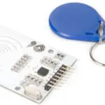
![]() QM-201C-HF Contactless Card Read or Write Module
QM-201C-HF Contactless Card Read or Write Module
User Manual
QM-201C-HF Contactless Card Read or Write Module
Contactless Card Read/Write Module QM-201C-HF
Contactless Card Read/Write Module
QM-201C-HF
User’s Manual
(version 1.4)
WEB: www.quio-rfid.de
MSN&EMAIL: kontakt@quio-rfid.de
PHONE:+49 (0) 202 404329
MOBILE: +49 (0) 202 404350
Summary
QM-201C-HF contactless card Read/Write module was designed on high integrated reader ICs for contactless communication on 13.56MHz of Philips.QM-201 integrates MF RC500 RF base station . Engineers need not take care how to control MF RC500 RF base station. Just send command to module over IIC or UART.
QM-200 series contactless card Read/Write module support ISO14443-A Mifare One S50,S70,UltraLight,MifarePro,ISO14443-B SR176, ISO15693 ,I CODE SL2 and then other compatible card.
QM-200 Series Module
| Type | Card Protocol | Vcc | Interface | Card | supported This Page |
| QM-201C-I- | 15014443- | +5V | IIC,UART(TTL) | Mifare S50,S70, Mifare Pro | I |
| QM-202-C | IS014443-A ISO 14443-B |
+3.3V-1-5V | IIC,UART(TTL) | Mifare S50,S70, Mifare Pro, IS014443-B SR176 |
|
| QM-203-C | 19315693 | +3.3V-1-5V | IIC,UART(TTL) | ICode SL2, IS015693 | |
| QM-204-C | IS014443-A IS014443-B IS015693 |
+3.3V–+5V | IIC,UART(TTL) | Mifare S50,S70, Mifare Pro, 18014443—B SR176, ICode SL2, IS015693 |
QM-201C-HF Characteristic
☞Completely operation of Mifare One through simple command set.
Contactless Card Read/Write Module(QM-201C-HF)User’s Manual
☞Communication Protocol:
1. UART: Baud Rate 19200bps。
2. IIC:Max rate 400Kbps。
☞Auto request card: When the card put into antenna, the pin “CARDIN” will be low.
☞Power supply :+4.5~+5.5V.
☞Read Card distance 5~10cm.(Depend on the antenna)
☞You can get C51 source code example with theh module.
Function specification
4.1 Pin Function
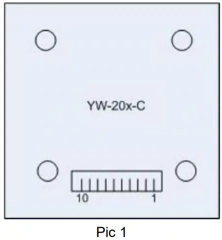 Pin function [Table 1]:
| Pin | Function | Description |
| 1 | VCC | +5V VCC |
| 2 | GND | GND |
| 3 | RXD/SCL | UART RXD/ IIC SCL |
| 4 | TXD/SDA | UART TXD/ IIC SDA |
| 5 | CARDIN | Card In/Out Indicate(Only when auto request) O:Card In. 1:Card Out. |
| 6 | PORTSEL | Communication Protocol Selector ( 0: IIC, 1: UART ) |
| 7 | NC | Not Use |
| 8 | NC | Not Use |
| 9 | NC | Not Use |
| 10 | NC | Not Use |
4.2 Dimension
Protocols
5.1 UART Protocols of Commands
Uart Protocols of Commands use data blocks.The format of data block :
1) Format of TXD(MCU → QM-201C-HF Module)
| [SIX] | [LEN] | [CMD] | [DATA] | [CHK] | [ETX] | |
| Description | 0x02 | Package Length | Commad | The Content of bytes |
CheckSum | 0x03 |
| Number of Byte | 1 | 1 | 1 | n | 1 | 1 |
Table 2
a) Asynchronism half duplex, 1 Start bit + 7 Data bits + 1 Stop bit.
b) The default transfer speed is 19200 bit/s.
c) Block Header STX=0x02, Block End ETX=0x03. From header to end ,but not include the header STX and the end ETX, if there is 0x02,0x03 or 0x10 , then must add 0x10 before it.
d) Block Header STX=0x02.
e) Package Length: the byte from Length itself to Checksum, but not include the added byte 0x10 due to 0x02,0x03 or 0x10.
f) Command: Refer to the Command List.
g) The Content of n bytes: the parameter.
h) CheckSum: XOR result from [Length] to then last byte of [Content], but not include the added byte 0x10 due to 0x02,0x03 or 0x10.
i) Block End ETX=0x02.
Example:
CMD: 0x10,DATA:0x00
Block Header:0x02。
LEN:0x04(=1Byte(Len) +1Byte(CMD)+1Byte(DATA)+1Byte(CHK))
CMD:0x10,0x10. (Add 0x01 before 0x10)
DATA:0x00。
CHECKSUM:0x14(=0x04^0x10^0x00)
Package Send:0x02,0x04,0x10,0x10,0x00,0x14,0x03.
2) Respond Format(QM-201C-HFmodule → MCU )
| [STX] | [LEN] | [CMD] | [STATUS] | [DATA] | [CHK] | [ETX] | |
| Content | 0x02 | Package Length | Command | Ox00: Success OxFF: Fail |
The Content of bytes |
CheckSum | 0x03 |
| Num of Byte | 1 | 1 | 1 | 1 | n | 1 | 1 |
Table 3
a) Asynchronism half duplex, 1 Start bit + 7 Data bits + 1 Stop bit.
b) The default transfer speed is 19200 bit/s.
c) Block Header STX=0x02, Block End ETX=0x03. From header to end ,but not include the header STX and the end ETX, if there is 0x02,0x03 or 0x10 , then must add 0x10 before it.
d) Block Header STX=0x02.
e) Package Length: the byte from Length itself to Checksum, but not include the added byte 0x10 due to 0x02,0x03 or 0x10.
f) Command: Refer to the Command List.When the MCU send the command to the module, the module send back this command to the MCU.
g) Status: Operation result. Success: 0x00. Fail: 0xFF.
h) During the communication, command content.
i) CheckSum: XOR result from [Length] to then last byte of [Content], but not include the added byte 0x10 due to 0x02,0x03 or 0x10.
j) Block End ETX=0x02.
5.2 IIC Protocol
1) Format of TXD(MCU → QM-201C-HF Module)
| [Address of module] (W/R) | [LEN] | [CMD] | [DATA] | [CHK] | |
| Content | Write: OxAO | Package Length | Command | The Content of n bytes |
CheckSum |
| Read: OxAl | |||||
| Num of Byte | 1 | 1 | 1 | n | 1 |
Table 4
a) Address of module (W/R):
b) When Write to module, the Address is 0xA0.
c) When Read from module, the Address is 0xA1.
d) Package Length: the byte from Length itself to Checksum.
e) Command: Refer to the Command List.
f) The Content of n bytes: the parameter.
g) CheckSum: XOR result from [Length] to then last byte of [DATA].
2) Respond Format(QM-201C-HFmodule → MCU)
| [LEN] | [CMD] | [STATUS] | [DATA] | [CHK] | |
| Content | Package Length | Command | Ox00: Success OxFF: Fail | The Content of n bytes |
CheckSum |
| Num of Byte | 1 | 1 | 1 | n | 1 |
Table 5
h) Package Length: the byte from Length itself to Checksum.
i) Command: Refer to the Command List.
j) Status: Operation result. Success: 0x00. Fail: 0xFF.
k) The Content of n bytes: the parameter.
l) CheckSum: XOR result from [Length] to then last byte of [DATA].
5.3 Switch of Uart and IIC
QM-201C-HF Contactless card read/write module support UART and IICthey can be switched by the port PORTSEL
PORTSEL = 1(High), UART is selected.
PORTSEL = 0(Low), IIC is selected.
Command List
| [CMD Name] | [Dir] | [LEN] | [CMD] | [STATUS and DATA] | [Description] | |
| System Command | ||||||
| 1 | Modue Setting | Send | 0x04 | Ox01 | Ox00 | 4 combination with bit() and bit1: Antenna Status (BITO) 0: Turn off Antenna 1: Turn on Antenna |
| Ox01 | ||||||
| 0x02 | ||||||
| 0x03 | Auto Request (BITI) 0: Turn off Auto Request 1: Turn on Auto Request |
||||||
| Recurn | Ox04 | Ox01 | 0x00 | Status: Ox00: Success OxFF: Fail |
|||
| OxFF | |||||||
| 2 | Power Setting | 0x03 | 0x02 | ||||
| Recurn | 0x04 | 0x02 | Ox00 | Status: Ox00 -Success OxFF: Fail |
|||
| OxFF | |||||||
| Contact less card Command | |||||||
| 1 | Request Card | (kW | Ox10 | Ox00 | Request card modes Ox00: request all card in antenna area °set: request card that have not halted in antenna area |
||
| Ox01 | |||||||
| Recurn | 108 | oxio | 0x00 | Serial No | Status: Ox00: Request success + Card Serial No(4 bytes). OxFF: Request Fail. |
||
| 0x04 | OxFF | ||||||
| 4 | Read Block |
Send | OxOB | Ox11 | 8Byte | Key Set(IByte)+Block No(lByte) 4 Key (6Bytes) a.Key Set (1Byte) t Select Key A. B(BITIB ->O:Key A: 1:Key B Key Ilode(BITI)-> O:Use key passed. 1:Use key downloaded. b.Index of Key Downloaded(BITe11117) ->O’31 |
|
| Recurn | 0x14 | Oat I | Ox00 | Data | Ox00: Success. 16 bytes of data return. | ||
| Ox04 | OxFF | OxFF: Fail | |||||
| S | Mile Block | Send | OxIB | Ox12 | 24bytes | Key set (1Byte) +Block %(illy te) + Key (011ytes)+ Data (16Bytes) a. Key Set (IByte): Select Key A. B(BITO)->O:Key A: 1:Key B |
|
| ->0’31 | |||||||
| ,117 | I I | 0x12 | Ox00 | Status: Ox00: Success OxFF: Fail |
|||
| OxFF | |||||||
| 6 | Read Sector | Send | OxOB | 0x13 | Kbytes | Key Set (IByte) + Index of Sector (IByte) +Key (6Bytes) a.Key Set (IByte): Select Key A.B(BITO)-)O:Key A:I:Key B Key Ilode(BITI)-> O:Use key passed. I:Use key downloaded. b.Index of Key Downloaded(BIT2-BIT7) -4’31 |
|
| Rawn | 0x44 | Ox113 | Ox00 | Data | Ox00: success. Mbytes of data return. | ||
| 0x04 | 0x13 | OxFF | OxFF: Fail | ||||
| 7 | Initialize purse | Send | OxOF | 4 | I2Bytes | Key Set (IByte) +I ndex of Block (IByte)+ Key (6Bytes) +Purse Initial Value (4aytes. LSB) a.Key Set (lByte) I Select Key A,BWITC0->O:Key A; I:Key B Key Mode(BITI)-> O:Use key passed. I:Use key downloaded. b. Index of Key Downloaded(13112% BITD ->C31 |
|
| Rawn | 0x04 | 0x14 | Ox00 | Slaws: Ox00: Success OxFF: Fail |
|||
| OxFF | |||||||
| 8 | 131 | Send | OxOB | Ox15 | SBytes | Key Set (IByte)+Index of Block(lByte)+ Key (BBytes) a.Key Set(lByte)i Select Key A.B(BITO)->0:1Cey A;I:Key B Key Node (BITI)-> O:Use key passed. I:Use key downloaded. b. Index of Key Downloaded(BITfIlIM ->O’31 |
|
| Recurn | Ox08 | Ox15 | Ox00 | Data | 040: Success. abytcs of purse valuellSBI | ||
| 0x04 | OxFF | OxFF: Fail | |||||
| 9 | doarnent | Send | OxOF | Ox16 | I2Byes | Key Set (IByte)+ Index of Block(lByte)+ Key (6Byt es) + value of decrement (-Myles, LSB) a.Key Set (1Byte1: Select Key A.B(BITC)-)0:Key A:1:Key B Key llode(BITI)-> 0:Use key passed. I:Use key downloaded. b.Index of Key Dom loaded (BITaM ) ->O’31 |
| Recurn | 4 | 0x16 | Ox00 | Status: Ox00: Success OxFF: Fail |
||
| OxFF | ||||||
| 10 | Increment | Send | OxOF | 0x17 | 12Bytes | Key Set (IByte)+Index of Block(lByte)+ Key (6By tee) + value of Increment (4Byt es. LSB) a.Key Set (-Byte): Select Key A.B(BITO)->0:Key A:I:Key B Key Ilode(BITI)-) 0:Use key passed. I:Use key downloaded. b.Index of Key Downloaded (BITeBIT7) ->O’31 |
| i – | Ox04 | 0x17 | Status: | Ox00: Success OxFF: Fail | ||
| OxFF | ||||||
| II | Purse backup | Send | OxOC | Ox18 | 9Bytes | Key Set (IByte)+ Index of Block(lByte)+ Index of Block Backup(IByte) +Key (6Byte) a.Key Set (IByte): Select Key A.B(BITO)->0:Key A:I:Key B Key llode(BITI)-> 0:Use key passed. I:Use key downloaded. b.Index of Key Downloaded(BIT2.13ITD ->O’31 ps: the index of block and the backup block must be in the sae sector. |
| Rettign | OxOC | Ox18 | Ox00 | Status: Ox00: Success OxFF: Fail |
||
| OxFF | ||||||
| 12 | Card Halt | Send | 0x03 | 0x19 |
| Retur | 0x04 | 0 \ 19 Ox00 |
§ORR: Success OxFF: Fail | ||||
| OxFF | |||||||
| 13 | Key Download |
Send | OxOA | Ox I A | Index of key(lByte , 0-31 ) + Key (6Bytes ) |
||
| Return | 0x04 | Ox 1 A | Ox00 | Status: Ox00: Success OxFF: Fail |
|||
| OxFF | |||||||
| 14 | Read RC500 EEPROM |
Send | Ox06 | OxIB | Address(2Bytes)-1-Legnth(1Bytes) Ps: Address: High byte afront Length: not more than 16 |
||
| Return | n+4 | OxIB | Ox00 | Data | Ox00: success, n(Length) bytes of data return. | ||
| 0x04 | OxFF | OxFF: fail | |||||
| 15 | Write RC500 EEPROM |
Send | n + 5 | Ox I C | N bytes data Ps: |
Address(2Bytes)+Data(nBytes) Address: High byte afront Data: not more than 16 bytes. |
|
| Return | 0x04 | Ox1C | Ox00 | Status: Ox00: Success OxFF: Fail |
|||
| OxFF | |||||||
Table 6
Tips Turn on the antenna before the operation of contactless card.
Command test sample
Samples below are based on uart protocol.
7.1.request card
Send:02 04 10 10 00 14 03
Receive:02 08 10 10 00 4D 56 A2 57 F6 03
7.2.read block
Send:02 0B 11 00 3E FF FF FF FF FF FF 24 03
Receive:02 14 11 00 00 01 00 00 00 00 00 00 00 00 00 00 00 00 00 00 04 03
7.3.write block
Send:02 1B 12 00 3E FF FF FF FF FF FF 00 01 00 00 00 00 00 00 00 00 00 00 00 00 0Receive:02 04 12 00 16 03
7.4.download key
Send:02 0A 1A 00 FF FF FF FF FF FF 10 10 03
Receive:02 0A 1A 00 FF FF FF FF FF FF 10 10 03
7.5.initial purse
Send:02 0F 14 00 3D FF FF FF FF FF FF 01 00 00 00 27 03
Receive:02 04 14 00 10 10 03
7.6.read purse
Send:02 0B 15 00 3D FF FF FF FF FF FF 23 03
Receive:02 08 15 00 10 02 00 00 00 1F 03
7.7.increment of purse
Send:02 0F 16 00 3D FF FF FF FF FF FF 01 00 00 00 25 03
Receive:02 04 16 00 12 03
7.8.decrement of purse
Send:02 0F 17 00 3D FF FF FF FF FF FF 01 00 00 00 24 03
Receive:02 04 17 00 13 03
7.9.purse backup
7.9.1 initial purse 1
Send:02 0F 14 00 3D FF FF FF FF FF FF 01 00 00 00 27 03
Receive:02 04 14 00 10 10 03
7.9.2 initial purse 2
Send:02 0F 14 00 3C FF FF FF FF FF FF 05 00 00 00 22 03
Receive:02 04 14 00 10 10 03
7.9.3 purse backup from 1 to 2
Send:02 0C 18 00 3D 3C FF FF FF FF FF FF 15 03
Receive:02 04 18 00 1C 03
7.9.4 read purse 2
Send:02 0B 15 00 3C FF FF FF FF FF FF 22 03
Receive:02 08 15 00 FF 04 00 00 E6 03
7.10.card halt
Send:02 10 03 19 1A 03
Receive:02 04 19 00 1D 03
7.11.read RC500EEPROM
Send:02 06 1B 00 70 10 10 7D 03
Receive:02 14 1B 00 00 00 00 00 00 00 00 00 00 00 00 00 00 00 00 00 0F 03
7.12.write RC500EEPROM
Send:02 15 1C 00 70 FF FF FF FF FF FF FF FF FF FF FF FF FF FF FF FF 79 03
Receive:02 04 1C 00 18 03
7.13.module IDLE
Send:02 10 03 10 02 01 03
Receive:02 04 10 02 00 06 03
7.14.module set
Send:02 04 01 00 05 03(turn off antenna)
Receive:02 04 01 00 05 03
Send:02 04 01 01 04 03(turn on antenna)
Receive:02 04 01 00 05 03
Order
Web:www.quio-rfid.de
Phone:+49 (0) 202 404329
Email:kontakt@quio-rfid.de
![]() Contactless Card, RFID…
Contactless Card, RFID…
www.quio-rfid.de
Documents / Resources
 |
QUIO QM-201C-HF Contactless Card Read or Write Module [pdf] User Manual QM-201C-HF, Contactless Card Read or Write Module, QM-201C-HF Contactless Card Read or Write Module, Card Read or Write Module, Read or Write Module, Module |