Quantek KPN Access Control Keypad and Reader

Please read the manual carefully before installing this unit
Packing list
| Name | Quantity | Remarks |
| Keypad | 1 | |
| User manual | 1 | |
| Screwdriver | 1 | |
| Wall plugs | 2 | Used for fixing |
| Self-tapping screws | 2 | Φ4mm×25 mm, used for fixing |
| Master cards | 2 | Add & delete |
| Diode IN4004 | 1 | For relay circuit protection |
Please ensure that all the above contents are correct. If any are missing, please notify us immediately.
Description
The KPN is a single-door multifunction standalone access controller or a Wiegand output keypad/card reader. It is suitable for mounting either indoors or outdoors in harsh environments. It is housed in a strong, sturdy, and vandal-proof zinc alloy powder coated case. It uses Atmel MCU assuring stable performance. The operation is very user-friendly, and the low-power circuit ensures a long service life. This unit supports up to 1000 users (998 common users and 2 panic users), all user data can be transferred from one to another which is very useful if there a multiple KPNs on the same site, as only 1 has to be programmed saving time. The inbuilt card reader supports 125KHZ EM cards. The unit has many extra features including Wiegand output, interlock mode, and backlit keys. These features make the unit an ideal choice for door access not only for small shops and domestic households but also for commercial and industrial applications such as factories, warehouses, laboratories, etc.
Features
- Supports wide voltage input 12-28Vac/dc
- Waterproof, conforms to IP66
- Strong zinc alloy powder-coated anti-vandal case
- Full programming from the keypad
- 1000 users, support card, PIN, or card + PIN
- PIN length 4-6 digits
- Backlit keys
- Wiegand 26-37 bits input & output
- Tri-colour LED status display
- Integrated alarm and buzzer output
- Pulse or toggle mode
- User data can be transferred
- 2 devices can be interlocked for 2 doors
- Built-in light-dependent resistor (LDR) for anti-tamper
Specification
| Operating voltage
Idle current consumption Max current consumption |
12-28Vac/dc
<35mA <80mA |
| User capacity
Common users Panic users |
1000
998 2 |
| Proximity card reader
Frequency Card reading distance |
EM
125KHz 2-6 cm |
| Wiring connections | Relay output, exit button, alarm, door contact, Wiegand input, Wiegand output |
| Relay
Adjustable relay time Relay maximum load |
One (Common, NO, NC)
1-99 seconds (5 seconds default), or Toggle mode 2Amp |
| Wiegand interface
Wiegand input Wiegand output PIN output |
Wiegand 26-37 bits (Default: Wiegand 26 bits, 4bits)
26-37 bits 26-37 bits 4 bits, 8 bits(ASCII), 10 digits virtual number |
| Environment
Operating temperature Operating humidity |
Meets IP66
-45 to 60⁰C 0%RH to 98%RH |
| Physical
Color Dimensions Unit weight |
Zinc alloy
Silver 134 x 55.5 x 21mm 340g |
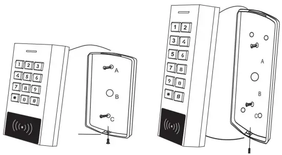
Installation
- Remove the back cover from the keypad using the supplied special screwdriver.
- Mark and drill two holes on the wall for the self-tapping fixing screws and one for the cable.
- Put the two wall plugs into the fixing holes.
- Fix the back cover firmly on the wall with the two self-tapping screws.
- Thread the cable through the cable hole.
- Attach the keypad to the back cover.
Wiring
| Color | Function | Description |
| Basic standalone wiring | ||
| Red | AC/DC | 12-28Vac/dc regulated power input |
| Black | AC/DC | 12-28Vac/dc regulated power input |
| Pink | GND | Ground |
| Blue | NO | The relay normally opens the output |
| Purple | COM | Relay output common |
| Orange | NC | Relay normally closed output |
| Yellow | OPEN | Exit button input (Normally open, connect other end to GND) |
| Pass-through wiring (Wiegand reader or controller) | ||
| Green | D0 | Wiegand input/output Data 0 |
| White | D1 | Wiegand input/output Data 1 |
| Advanced input and output features | ||
| Grey | ALARM | External alarm output negative |
| Brown | D_IN
DOOR CONTACT |
Door/gate magnetic contact input (Normally closed, connect
other end to GND) |
- Note: If an exit button is not being connected, it is advisable to still run the yellow wire back to the power supply and leave it taped up or on a terminal block.
- This will make it easier to perform a factory reset at a later date if required, avoiding the need to remove the keypad from the wall.
- See the last page for more information about how to perform a factory reset.
- Tape all unused wires to prevent short circuits.
Sound & light indication
| Operation | LED indicator | Buzzer |
| Standby | Red | |
| Enter programming mode | Red flashing slowly | One beep |
| In a programming menu | Yellow | One beep |
| Operation error | Three beeps | |
| Exit programming mode | Red | One beep |
| Door unlocked | Green | One beep |
| Alarm | Red flashing quickly | Alarming |
Simplified quick programming guide
| Enter programming mode | * 123456 #
Now you can do the programming. 123456 is the default master code. |
| Change master code | 0 New Master code # New Master code #
The master code is any 6-digit |
| Add card user | 1 Read card #
Cards can be added continuously without exiting the programming mode |
| Add PIN user | 1 PIN #
PINs can be added continuously without exiting the programming mode. The PIN is any 4-6 digit number, except 8888 which is reserved. |
| Delete user | 2 Read card # for the card user
2 Input PIN # for PIN user |
| Exit programming mode | * |
| How to release the door | |
| Card user | Read card |
| PIN user | Input PIN# |
Standalone mode
- The KPN can be used as a standalone reader for a single door or gate
- Master code # 7 2 # (Factory default mode)
Wiring diagram – Lock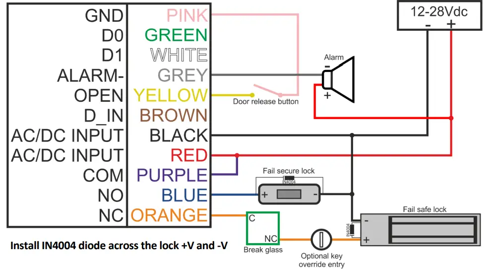
Wiring diagram – Gate, barrier, etc. 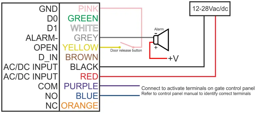
Set a new master code
| 1. Enter programming mode | * Master code #
123456 is the default master code |
| 2. Change master code | 0 New Master code # New Master code #
The master code is any 6-digit |
| 3. Exit programming mode | * |
It is highly advised to keep a record of the User ID number and card number to allow for individual deletion of cards and PINs in the future, see the last page.
Add common users – card
| 1. Enter programming mode | * Master code #
123456 is the default master code |
| 2. Add a card user (Method 1)
The KPS will automatically assign the card to the next available user ID number |
1 Read card #
Cards can be added continuously without exiting the programming mode |
| 2. Add a card user (Method 2)
In this method, a user ID number is allocated to a card. User ID number is any number from 0-997. Only one user ID number per card. |
1 User ID number # Read card #
Cards can be added continuously without exiting the programming mode |
| 2. Add a card user (Method 3)
In this method, the card is added by the 8 or 10-digit card number printed on the card. The user ID number is automatically assigned. |
1 Card number #
Cards can be added continuously without exiting the programming mode |
| 2. Add a block of sequential card numbers
Allows the manager to add up to 998 cards with sequential numbers to the reader in a single step. Can take up to 2 minutes to program. |
1 User ID number # Card quantity # First Card number # |
| 3. Exit programming mode | * |
Add common users – PIN
| 1. Enter programming mode | * Master code #
123456 is the default master code |
| 2. Add a PIN (Method 1)
The KPS will automatically assign the PIN to the next available user ID number |
1 PIN #
PINs can be added continuously without exiting the programming mode. The PIN is any 4-6 digit number, except 8888 which is reserved. |
| 2. Add a PIN (Method 2)
In this method, a user ID number is allocated to a PIN. User ID number is any number from 0-997. Only one user ID number per PIN. |
1 User ID number # PIN #
PINs can be added continuously without exiting the programming mode. The PIN is any 4-6 digit number, except for 8888 which is reserved. |
| 3. Exit programming mode | * |
Add panic users
When a panic PIN is entered or a panic card is read, the unit will still grant access normally, but the external alarm will be activated. The unit must be depowered to turn off the panic alarm.
| 1. Enter programming mode | * Master code #
123456 is the default master code |
| 2. Add a card OR
Add a PIN |
1 User ID number # Read card OR Input 8/10 digit card number #
1 User ID number # PIN # The user ID number is 998 or 999 |
| 3. Exit programming mode | * |
Assign a PIN to a card user
Firstly, add a card as per the previous page
| Note this is done outside of programming mode, users can undertake this themselves | |
| 1. Assign a PIN to a card user | * Read card 8888 # New PIN # Repeat new PIN # |
| 2. Exit | * |
Change PIN users
| Note: this is done outside of programming mode, users can undertake this themselves | |
| 1. Change PIN by card | * Read card Old PIN # New PIN # Repeat new PIN # |
| 2. Change PIN by user ID | * User ID # Old PIN # New PIN # Repeat new PIN # |
| 3. Exit | * |
Delete common users – card
| 1. Enter programming mode | * Master code #
123456 is the default master code |
| 2. Delete a card user (Method 1)
Delete the user by reading their card |
2 Read card #
Cards can be deleted continuously without exiting programming mode |
| 2. Delete a card user (Method 2)
Delete the user by user ID number. This method is useful if the user has lost their card |
2 User ID number #
Cards can be deleted continuously without exiting programming mode |
| 2. Delete a card user (Method 3)
Delete the user by the 8/10 digit card number. This method is useful if the user has lost their card |
2 Input card number #
Cards can be deleted continuously without exiting programming mode |
| 3. Exit programming mode | * |
Delete common users – PIN
| 1. Enter programming mode | * Master code #
123456 is the default master code |
| 2. Delete a PIN (Method 1)
Delete the user by entering their PIN |
2 Input PIN #
PINs can be deleted continuously without exiting the programming mode |
| 2. Delete a PIN (Method 2)
Delete the user by user ID number |
2 User ID number #
PINs can be deleted continuously without exiting the programming mode |
| 3. Exit programming mode | * |
Delete panic users
| 1. Enter programming mode | * Master code #
123456 is the default master code |
| 2. Delete a panic user
Delete the user by entering their PIN |
2 User ID number #
The user ID number is 998 or 999. The method is the same for cards and PINs |
| 3. Exit programming mode | * |
Delete ALL users
| 1. Enter programming mode | * Master code #
123456 is the default master code |
| 2. Delete all users | 2 Master code # |
| 3. Exit programming mode | * |
Set relay configuration
| 1. Enter programming mode | * Master code #
123456 is the default master code |
| 2. Pulse mode
OR 2. Latch mode |
3 1-99 #
The relay time is 1-99 seconds. (1 equals 50mS). The default is 5 seconds. 3 0 # Read valid cards, relay switches. Read the valid card again, relay switches back. |
| 3. Exit programming mode | * |
Set access mode
| 1. Enter programming mode | * Master code #
123456 is the default master code |
| 2. Card only
OR 2. Card + PIN OR 2. Card or PIN OR 2. Multi cards/PINs access |
4 0 #
4 1 #
4 2 # (Default)
4 3 (2-9) # Only after reading 2-9 cards or inputting 2-9 PINs can the door be opened. The interval time between reading cards/inputting PINs cannot exceed 5 seconds or the unit will exit to standby. |
| 3. Exit programming mode | * |
Set strike-out alarm
The strike-out alarm will engage after 10 consecutive failed card attempts. Factory default is OFF. It can be set to deny access for 10 minutes or activate the reader’s internal alarm.
| 1. Enter programming mode | * Master code #
123456 is the default master code |
| 2. Strike-out OFF
OR 2. Strike-out ON OR 2. Strike-out ON (Alarm) Set alarm time |
6 0 #
No alarm or lockout (default mode)
6 1 # Access will be denied for 10 minutes
6 2 # The device will alarm for the time set below
5 0-3 # 0-3 is the time in minutes. Default is 1 minute. Enter master code # or valid card/PIN to silence |
| 3. Exit programming mode | * |
Set audible and visual response
| 1. Enter programming mode | * Master code #
123456 is the default master code |
|
| 2. Control Sounds | OFF = 7 0 # | ON = 7 1 # (Default) |
| 2. Control LED | OFF = 7 4 # | ON = 7 5 # (Default) |
| 2. Control backlit keys | OFF = 7 6 # | ON = 7 7 # (Default) |
| 3. Exit programming mode | * | |
Master cards usage
| Using master cards to add and delete card users | |
| Add a user | 1. Read master add card
2. Read card user (Repeat for additional user cards, the user ID number will be assigned to the next available slot) 3. Read master add card again |
| Delete a user | 1. Read the master delete card
2. Read card user (Repeat for additional user cards) 3. Read the master delete card again |
User operation
To open the door:
- Read a valid card or Input a valid PIN.
- If access mode is set to card + PIN, read the card first and enter the PIN within 5 seconds
To turn off the alarm:
- Read valid card or Enter valid PIN or Enter master code#
- The unit must be depowered to turn off the panic alarm.
Controller mode
- The XK1 can work as a controller, connected to an external Wiegand reader.
- Master code # 7 2 # (Factory default mode)
Wiring diagram – Lock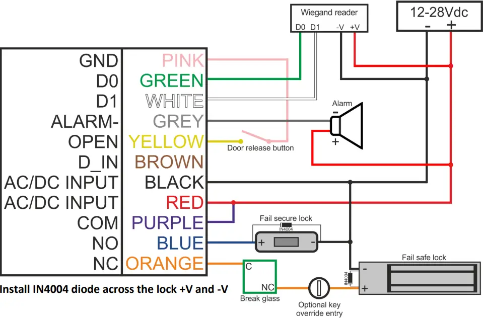
Wiring diagram – Gate, barrier, etc.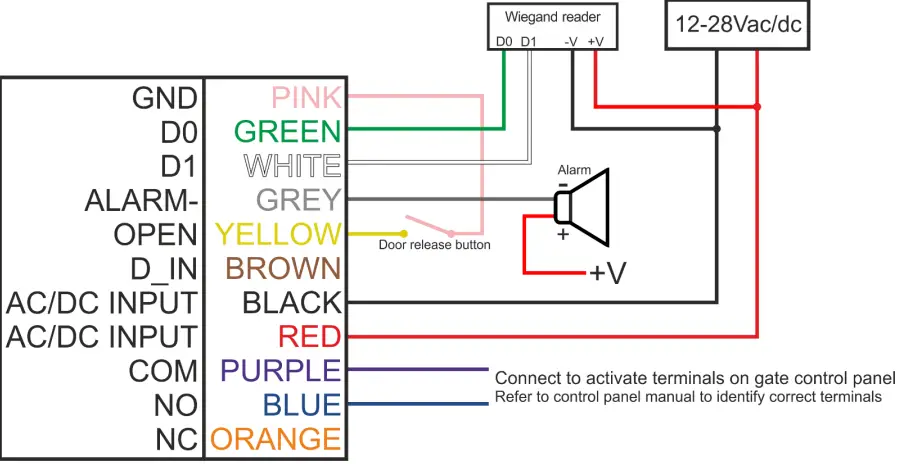
Set Wiegand input formats
Please set the Wiegand input format according to the Wiegand output format of the external reader.
| 1. Enter programming mode | * Master code #
123456 is the default master code |
| 2. Wiegand input bits | 8 26-37 # (Factory default is 26 bits) |
| 3. Exit programming mode | * |
If KPN is connected to a keypad reader
The keypad reader can be 4 bits, 8 bits (ASCII), or 10 bits in digital virtual number output format. Choose the below operation according to the PIN output format of your reader.
| 1. Enter programming mode | * Master code #
123456 is the default master code |
| 2. Wiegand input bits | 8 4 or 8 or 10 # (Factory default is 4 bits) |
| 3. Exit programming mode | * |
Programming
- Basic programming is the same as standalone mode.
- Notes: If the external reader is EM (125KHz), then cards can be added to either unit. PINs can be added to either unit.
Wiegand reader mode
The KPN can work as a standard Wiegand reader, connected to a third-party controller.
To set this mode:
| 1. Enter programming mode | * Master code #
123456 is the default master code |
| 2. Wiegand reader mode | 7 3 # (Factory default is 26 bits) |
| 3. Exit programming mode | * |
Wiring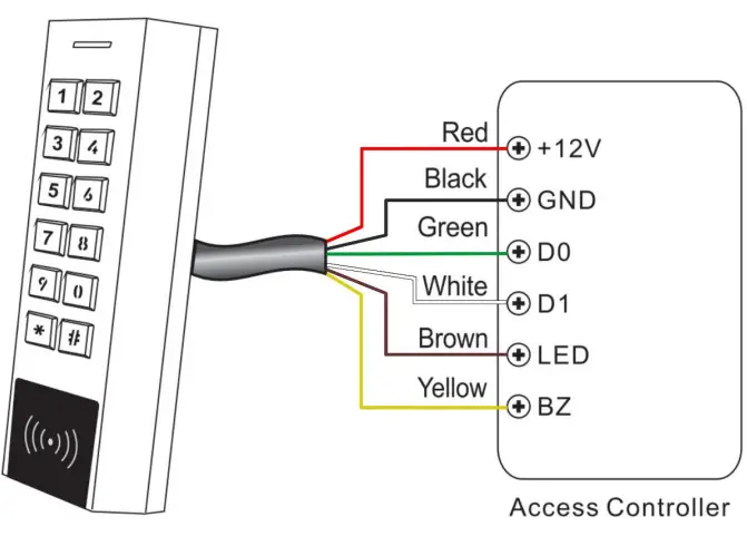
- When set to reader mode, brown and yellow wires are redefined to green LED control and buzzer control respectively.
- All programming is carried out at the third-party access controller.
Set Wiegand input formats
Please set the Wiegand input format according to the Wiegand output format of the external reader.
| 1. Enter programming mode | * Master code #
123456 is the default master code |
| 2. Wiegand input bits | 8 26-37 # (Factory default is 26 bits) |
| 3. Exit programming mode | * |
Advanced application
User information transfer
- The KPN supports the user information transfer function, allowing the enrolled users (cards and PINs) to be transferred to another KPS or KPN unit.
- This is useful when installing multiple KPS/KPNs on the same site and the users have the same access rights to all doors, as it means only one unit needs to be programmed and all data can be transferred to the other units saving a lot of time.
Wiring diagram: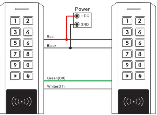
Notes:
- The master code must be the same on both units.
- Programming is done from the master unit only.
- If the receiving unit already has users enrolled, it will be overwritten.
- Transfer can take up to 3 minutes.
| 1. Enter programming mode | * Master code #
123456 is the default master code |
| 2. Start the transfer | 9 6 # |
| Within 3 minutes, the green LED will light up the unit will beep, the LED will turn red and the user information transfer is successfully completed. | |
| 3. Exit | * |
Interlock
The KPN supports a two-door interlocking function. A keypad is fitted to each door. Only when door 2 is fully closed can the user activate keypad 1, and vice versa.
Wiring diagram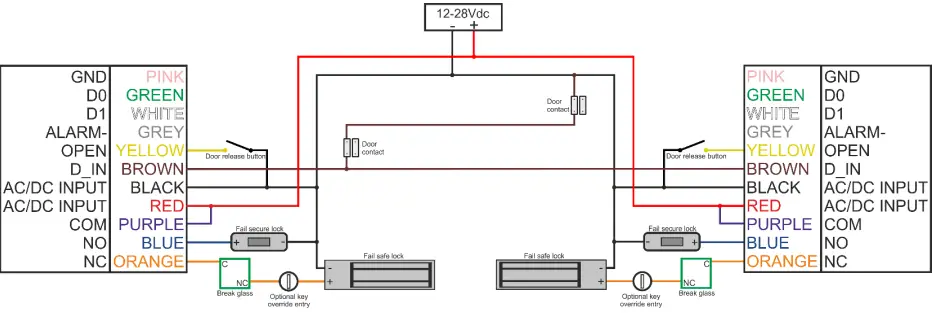
Install IN4004 diodes across the lock +V and -V
Notes:
- The door contact must be installed and connected as per the wiring diagram above.
- Enrol users on keypad 1, then transfer the users’ information to keypad 2 using the function explained on the previous page.
Set BOTH keypads to interlock mode
| 1. Enter programming mode | * Master code #
123456 is the default master code |
| 2. Turn ON interlock | 9 1 # |
| 3. Exit programming mode | * |
To turn off the interlock mode
| 1. Enter programming mode | * Master code #
123456 is the default master code |
| 2. Turn OFF interlock | 9 0 # |
| 3. Exit programming mode | * |
Factory reset & adding master cards
- Power off, press and hold the exit button whilst powering up the unit. There will be 2 beeps, release the exit button, the LED will turn yellow. Then read any two EM 125KHz cards, and the LED will turn red.
- The first card read is the master add card, the second card read is the master delete card. Factory reset is now complete.
- User data is unaffected.
Issue record
| Site: | Door location: |
| User ID No | User name | PIN | Card number | Issue Date |
| 0 | ||||
| 1 | ||||
| 2 | ||||
| 3 |
- Unit 11 Callywhite Business Park, Callywhite Lane, Dronfield, S18 2XP
- +44(0)1246 417113
- sales@cproxltd.com
- www.quantek.co.uk
Documents / Resources
 |
Quantek KPN Access Control Keypad and Reader [pdf] User Manual KPN Access Control Keypad and Reader, KPN, Access Control Keypad and Reader, Control Keypad and Reader, Keypad and Reader |


