![]() 2820 Wilderness Place, Unit C
2820 Wilderness Place, Unit C
Boulder, Colorado, 80301
Tel: (303) 443 6611
 Leap Wireless Sensor System
Flood / Water Detection
Device User Manual
53-100187-19
Revision 1.2
Copyright and Trademarks
No part of this product or related documentation shall be reproduced in any form by any means without prior written authorization of Phase IV Engineering, Incorporated. No part of this document shall be reproduced, stored in a retrieval system, or transmitted by any means, electronic, mechanical, photocopying, recording, or otherwise, without prior written permission from Phase IV Engineering, Incorporated.
Although every precaution has been taken in the preparation of this document, Phase IV Engineering assumes no responsibility for errors or omissions. Neither is any liability assumed for damages resulting from the use of the information contained herein.
Phase IV Engineering assumes no responsibility for any loss or claims by third parties that may arise through the use of this product.
Phase IV Engineering assumes no responsibility for any damage or loss caused by deletion of data as a result of malfunction, repairs, or battery replacement, or power failure.
Phase IV Engineering, Incorporated may have patents, patent applications, trademarks, copyrights, or other intellectual property rights covering subject matter in this document. Except as expressly provided in any written license agreement from Phase IV Engineering, the furnishing of this document does not give you any license to these patents, trademarks, copyrights, or other intellectual property.
This manual, its related hardware, software and documentation are subject to change without notice and do not represent a commitment on the part of Phase IV Engineering. Phase IV Engineering reserves the right to make changes in the product design without reservation and without notification to its users.
© 2021 by Phase IV Engineering, Incorporated, 2820 Wilderness Place, Unit C, Boulder, Colorado 80301,
USA. All rights reserved.
All brands and product names are trademarks or registered trademarks of their respective owners.
About this Manual
This User Manual describes specific configuration and usage of the Leap Flood Sensor Device.
For general information on the Leap Wireless Sensor system, see the Quick Start Guide and the main user manual – 53-100187-01.
Link to: Leap Wireless Sensor System User Manual
Hardware Configuration – Water Detection
The Leap Flood detection sensor utilizes an orange-colored plastic “rope”. This rope contains 2 wires that are covered with a water-conducting plastic.
When water touches the rope, the resistance between the wire drops and the “Raw ADC Value” reading lowers.
To a limited degree, the water sensor can report “% Saturation” as an increasing amount of water touches the rope. A puddle of water that is a few inches in diameter will typically report as 100% wet.
The water detection rope is very sensitive. For the sensor to report 0% saturated, the rope may need to thoroughly dry.
Software Interface
3.1 Main Devices Software Screen
See the screenshot below for information on the unique features in the flood sensor. (Consult the main user manual 54-100187-01 for the foundation software features).
 Special notes on the screenshot above…
- * The water rope is very sensitive. A small puddle of water that is a few inches in diameter (that is touching the rope anywhere) will typically register at 100% saturated.
- ** When the water rope is totally dry, the count is typically nearly 2000. When the rope is very wet, the count is typically below 50.
3.2 Special Software Configurations for the Water Rope Sensor
Click on the main user screen as shown below to enter the configuration screen.
 3.2.1 Configuring Normal Operation when the Water Rope is Dry
 3.2.2 Setting Thresholds on “Water Leak Detection” and % Saturation
 3.2.2.1 “Water Leak Detection” Configuration
In the configuration screen, the “Leak detected when ADC count below” sets the threshold when the “Water Leak Detection” field will switch from “No Leak” to “Leak”.
In the example above, the ADC count is currently at 1995 and the threshold for “Leak” is below 1800 – so the sensor is reporting “No Leak”.
In the example above, if water touched the rope, the ADC count would drop below 1900 and the “Water Leak Detection” would report, “Leak”.
The end-user may want to experiment with putting different amounts of water on the rope and adjusting the “Leak” limit to match the needs of the application.
3.2.2.2 % Saturation Configuration
To have the rope sensor report “% Saturation”, the 100% Raw ADC Count level and the 0% l Raw ADC Count level need to be set. Note: the count drops as the rope gets more-wet.
In the example above, the 0% Saturation level (totally dry) is set to 1800 and the 100% Saturation (totally wet) level is set to 0 Raw ADC counts.
Often the end-user may want to experiment with putting different amounts of water on the rope and adjusting these limits to report the % saturation that meets the needs of the application.
3.2.3 Faster Transmit When Wet Mode
The sensor has a special mode that allows the user to change the transmit time interval when the sensor has detected water.
To set-up this special mode, the “Normal Saturation Range” needs to be set. In the example below, this range is from 0% to 5%. This means that if the sensor is reporting 0% saturated to 5% saturated, this is the normal “not wet” range and the special faster-transmit will not be activated.
 3.2.4 Special Fast Transmit Mode for Testing and Installing
This sensor is intended to be used for long-term monitoring with transmit times between an hour to a day.
But, during testing and during installation, it helps if the sensor can temporarily be put into a special mode where it transmits much faster. This is called, “Installer Mode”
To activate Installer Mode, press the black push-button switch on the enclosure so that it is ‘pushed in’.
To de-activate this mode, press the black button again so that it is flush with the switch bezel.
In the example below, the flood sensor will sample the rope every 60 seconds and transmit every 60 seconds when the black switch is depressed.
IMPORTANT NOTE: Take care to only use the Installer Mode for short time spans to avoid large cellular usage charges.

Special Notes on Setting Text, Telephone, and Email Alerts
4.1 Creating a New Flood Alert
Follow the instructions below to set-up text, telephone, and email alerts.
Select the sensors that you want to apply an new alert by clicking the box as shown below.
 The alert screen…
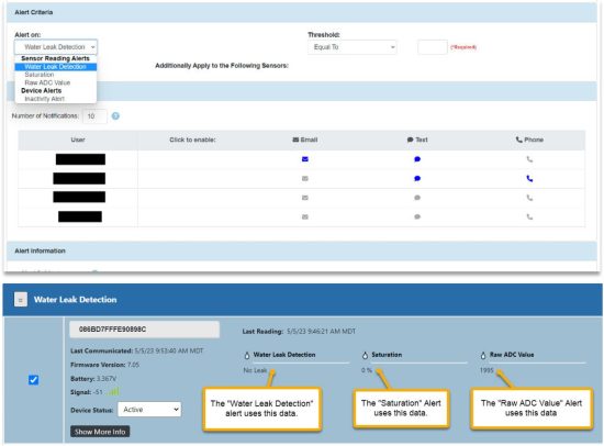
Water Leak Detection Alert: If you want to send an alert when the “Water Leak Detection” is reporting “Leak” set: “Threshold” to “Equal To” and enter: 1 in the next required field.
The other alerts may be set using the normal alert setting process.
NOTE: Inactivity alerts are recommended on all sensors to send an alert when a sensor transmission is over-due.
4.2 Editing Existing Alerts
To edit an existing alert, click on “Alerts” on the black bar at the top of the screen.
Technical Support
For more information about our products and services, or for technical assistance:
Visit us at: www.phaseivengr.com
Tel: +(303) 443 6611 (USA – MST 8:00 a.m. to 5:00 p.m., Mon.-Fri.)
E-Mail: support@phaseivengr.com
If you need assistance, please provide the product part number, product serial number, and product version.
LEAP SYSTEM
User’s Operating Manual
Documents / Resources
 |
Phase IV 53-100187-19 Wireless Sensor System Flood Water Detection Device [pdf] User Manual 53-100187-19, 53-100187-19 Wireless Sensor System Flood Water Detection Device, 53-100187-19, Wireless Sensor System Flood Water Detection Device, Flood Water Detection Device, Water Detection Device, Detection Device, Device |