NXP TWR-IND-IO Industrial IO Module
Get to Know the TWR-IND-IO
TWR-IND-IOFreescale Tower System
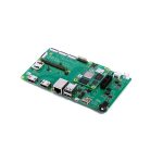
The TWR-IND-IO module is part of the Freescale Tower System, a modular development platform that enables rapid prototyping and tool re-use through reconfigurable hardware. Take your design to the next level and begin prototyping with your Tower System today.
TWR-IND-IO Features
- USB to Serial Ready Play solution, providing serial connectivity via USB
- RS-232 transceiver with available flow control signaling
- RS-485 transceiver with optional isolation and PROFIBUS capability
- Dual CAN transceivers
- Analog signals accessible via screw terminals: 3x ADC, 1x DAC, VDDA, VSSA
- Digital signals accessible via LEDs and thru-hole points: 6x PWM, 3x timer
- Signal jumpers to allow isolation, probing and remapping of interfaces
- Compatible with the TWR-SER to provide access to additional industrial I/O interfaces
Step-by-Step Installation Instructions
- Configure Jumpers
Configure the TWR-IND-IO jumpers to align with the intended Tower System controller module. Be aware that not all controller modules will provide access to all features available on the TWR-IND-IO. Refer to the Jumper Table in this document for reference and the user manual for additional details regarding the flexibility of this module. - Ensure Compatibility
Each interface featured on the TWR-IND-IO is capable of being isolated from the Tower System. To maintain the best compatibility with additional Tower peripheral modules it is recommended that any unused interfaces be isolated. - Assemble Your Tower System
Assemble your Tower System, including a Tower System controller module, the TWR-IND-IO peripheral module, and the TWR-ELEV elevator modules. Refer to the assembly instructions provided with the TWR-ELEV modules for correct orientation and assembly of boards. NOTE: The TWR-IND-IO module is intended to be compatible with the TWR-SER serial module, thus expanding the number of available interfaces. - Refer to Additional Materials
Many existing MQX™ example projects can be adapted to utilize the respective I/O interfaces on the TWR-IND-IO by modifying the “user_config.h” file and recompiling the MQX BSP. Refer to the TWR-IND-IO user manual and the latest MQX release notes for details. Refer to the TWR-IND-IO page on freescale.com/Tower for additional information and example application projects for select Tower System controller modules.
TWR-IND-IO Jumper Options
The following is a list of all jumper options. The default installed jumper settings are shown in white text within the black boxes.
| Jumper | Option | Setting | Description |
|
J3 |
LED Enable for Digital Signal Block A (3x PWM) |
1-2
1-2
1-2 |
Provides power to the associated LEDs, remove to isolate PWM signals or to use JP1 – JP3 |
|
J4 |
LED Enable for Digital Signal Block B (3x PWM) |
Provides power to the associated LEDs, remove to isolate PWM signals or to use JP4 – JP6 | |
| J5 | LED Enable for Digital Signal Block C (3x Timer) | Provides power to the associated LEDs, remove to isolate timer signals or to use JP7 – JP9 | |
|
J6 |
Voltage I/O selection |
1-2 | 5V interface between MCU and transceivers |
| 2-3
1-2
1-2
3-4 |
3.3V interface between MCU and transceivers | ||
| J7 | USB2SER RTS/CTS | Provides a loopback of RTS/CTS, remove to allow access to RTS and CTS | |
|
J9 |
USB2SER TX/RX |
Connects UART0 TX to USB2SER RX. Pin 1 – UART0 TX, Pin 2 – USB2SER RX | |
| Connects UART0 RX to USB2SER TX. Pin 3 – UART0 RX, Pin 4 – USB2SER TX | |||
| J13 | CAN1 Termination Enable | 1-2 | Enables 121 Ohm termination between CANH and CANL |
| J14 | CAN2 Termination Enable | 1-2 | Enables 121 Ohm termination between CANH and CANL |
|
J15 |
CAN Isolation Jumpers |
1-2
3-4
5-6
7-8 |
Connects CAN1_TX to TXD on CAN transceiver associated with J11 |
| Connects CAN1_RX to RXD on CAN transceiver associated with J11 | |||
| Connects CAN1_TX to TXD on CAN transceiver associated with J12 | |||
| Connects CAN1_RX to RXD on CAN transceiver associated with J12 |
| Jumper | Option | Setting | Description |
|
J16 |
UART3 Isolation/Access Jumpers |
1-2
3-4
5-6
7-8 |
Connects UART3_TX to T1IN on RS-232 transceiver associated with J17 |
| Connects UART3_RX to R1OUT on RS-232 transceiver associated with J17 | |||
| Connects UART3_RTS to T2IN on RS-232 transceiver associated with J17 | |||
| Connects UART3_CTS to R2OUT on RS-232 transceiver associated with J17 | |||
|
J18 |
UART3 RTS/DCD Loopback |
1-2 | Provides a loopback of RTS to DCD on UART3 |
| 2-3 | Provides a pulldown on UART3 DCD | ||
|
J19 |
UART2 RTS/DCD Loopback |
1-2 | Provides a loopback of RTS to DCD on UART3 |
| 2-3 | Provides a pulldown on UART3 DCD | ||
|
J20 |
UART2 Isolation/Access Jumpers |
1-2
3-4
5-6
7-8 |
Connects UART2_RX to R on RS-485 transceiver associated with J22/J23 |
| Connects UART2_TX to D on RS-485 transceiver associated with J22/J23 | |||
| Connects UART2_RTS to DE on RS-485 transceiver associated with J22/J23 | |||
| Connects UART2_CTS to a pull-down resistor | |||
| J21 | RS-485 Termination Enable | 1-2 | Enables 121 Ohm termination between RS-485 A and B |
TWR-IND-IO Header Descriptions
The following is a list of all available headers and their descriptions
| Header | Description | Pin Details |
| J2 (J24, J25) |
Analog Screw Terminal |
1-VDDA, 2-VSSA, 3-DAC0,
4-VSSA, 5-AN1, 6-AN2 7-AN3, 8-VSSA, 9-VDDA |
| J7 | USB2SER RTS/CTS | 1-CTS, 2-RTS |
| J8 | UART1 | 1-TXD1, 2-RXD1, 3-RTS1,
4-CTS1 |
| J11 | CAN1 Header | 1-CANH, 2-GND, 3-CANL |
| J12 | CAN2 Header | 1-CANH, 2-GND, 3-CANL |
|
J17 |
RS-232 Header |
3-TXD, 4-CTS, 5-RXD, 6-RTS,
9-GND (others signals are NC) |
| J22 | RS-485 Screw Terminal (Power) | 1-Isolated GND, 2-Isolated VCC, 3-Isolated GND |
| J23 | RS-485 Screw Terminal (Signal) | 1-Isolated DE, 2-RS-485 B, 3-RS-485 A |
Visit freescale.com/Tower for information on the TWR-IND-IO module, including:
- TWR-IND-IO user guide
- TWR-IND-IO schematics
- Tower System fact sheet
Support
Visit freescale.com/support for a list of phone numbers within your region.
Warranty
Visit freescale.com/warranty for complete warranty information. For more information, please visit freescale.com/Tower Join the online Tower community at towergeeks.org
Freescale and the Freescale logo are trademarks of Freescale Semiconductor, Inc., Reg. U.S. Pat. & Tm. Off. All other product or service names are the property of their respective owners. Apple, iPad, iPhone and iPod are trademarks of Apple Inc., registered in the U.S. and other countries.
© 2012 Freescale Semiconductor, Inc. Document Number: TWRINDIOQSG REV 0 Agile Number: 924-27304 REV A
Documents / Resources
 |
NXP TWR-IND-IO Industrial I\O Module [pdf] User Manual TWR-IND-IO Industrial I O Module, TWR-IND-IO, Industrial I O Module, I O Module |