![]()
 Brukerhåndbok for CH341A-programmerer (fargelysversjon)
CH341A Programmer Instructions
(Color Light Version v1.5, v1.6, v1.7 Universal)
2023/8/18 Contents Table of Contents
Introduksjon av CH341A-programmerer
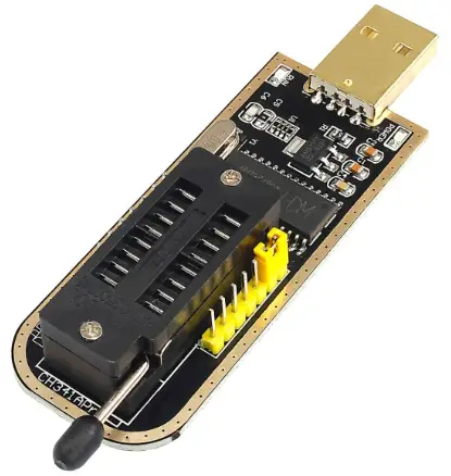
Our compact ch341a programmer is only 22mm*50mm in length and width, easy to carry around, with integrated level shifter circuitry, supporting 1.8v minimum. Based on the compact and convenient design considerations, so through the toggle switch K1 to change the voltage, can support 5v, 3.3v, 2.5v, 1.8v, also supports ttl output (minimum support 1.8v standard) It can be described as compact and multi-functional, burn 8-pin chip and not fall down the serial port brush, while integrated infrared code module. spi interface output support for low-voltage, også gjennom K1-bryteren for å oppnå.
Programvarenedlasting: http://198.11.174.230/ch341a-Software.zip
This is what our programmer looks like
Plug directly into the usb port and try to avoid grabbing space with other usb devices.
Meanwhile, in order to adapt to most of the 8-pin chips, we have also equipped with simple adapter boards for 25xx, 24xx, 93xx, 45xx and other packages, in order to fulfill the needs in one step. We will also design adapter boards for the packages you need later.
We have labeled the interface and voltage slår på brettet, slik at du ikke lenger trenger å bekymre deg for at du ikke finner instruksjonene.
Differences between v1.5, v1.6 and v1.7:
*Locking Block 25xx, 24xx No Resistor Pull-Up and Down
*v1.6 Locking Block 25xx Partial Resistor Pull-Up
*v1.7 Locking Block 25xx partial resistor pull-up, 24xx partial resistor pull-down
Uttalelse:
The ch341a programmer hardware is designed and developed by us and is copyrighted.
The software is open source or shareware and the copyright (authorship) belongs to them, please respect the fruits of their labor and thank them for their dedication and contribution to the programmer industry.
Maskinvaredelen av programmereren
Programmerens design er relativt liten, kan settes direkte inn i USB-porten for bruk, hvert grensesnitt og jumperfunksjon har innebygde instruksjoner, de fleste tilfellene kan forstås uten å se på instruksjonene. Programmereren har integrerte nivåskifterkretser og støtter et minimum volum.tage of 1.8v. Based on the compact and convenient design considerations, so through the toggle switch KI to change the voltage, can support 5v, 3.3v, 2.5v, 1.8v, also supports ttl output (minimum 1.8v low level) Directly support most of the 1.8v 24, 25 chips without the need for level shifter boards, such as w25q64fw, w25q128fw and so on. 1. Chip placement method
Please refer to the diagram below for placement of the chips, noting the orientation of the chips
Vi bruker et 16-pinners låsesete, hver 8-pinners for å utføre en serie brikkebrenning, kortet har plassert retningen til logoen. 45xx- og 93xx-brikkene bruker holdere, men du kan ikke sette brikkene direkte inn i låseholderne, det vil brenne brikkene. Vær oppmerksom på dette. Du kan bare bruke den spesielle adapteren vi leverte for å oppnå dette. Vær oppmerksom på at det finnes instruksjoner på adapterkortet for å sette brikken inn i den delen av holderen.
2. Utgang voltage Vout
Se K1-merkingen i diagrammet og jumperinstruksjonene på baksiden av programmereren. Dette er lese-/skrivebrikken og spi-pin-utgangsvolumettage, gjennom hele K1-bryteren for å oppnå forskjellig volumtages tilbake vippebryterposisjon som tilsvarer volumettage identifikasjon
 The programmer K1 position is normally issued for 3.3v.
**Toggle switch K1 increases the voltage all the way from the latch to the usb port.
**Please adjust the voltagfør du brenner brikken for å unngå å brenne brikken på grunn av høyt volum.tage, vippebryteren K1 kan ikke betjenes i programmereren når den er påslått. Trekk ut programmereren for å ringe opp, og koble den deretter til!
The toggle position is shown below:
a) 1.8v toggle switch position reference
b) Referanse for posisjon for vippebryter på 2.5 V
c) 3.3 V vippebryterposisjonsreferanse (standard)
 d) Referanse for 5V vippebryterposisjon

3. spi output (programmer mode)
Programmer J1 pin numbering, with corresponding description on the back
Standardinnstillingen til programmereren er å kortslutte pinnene 1–2 på spi-utgang J1. Følgende er en liste over J1-utgangspinfunksjoner
| J1 | 112 | 3 | 4 | 5 | 6 | 7 | 8 | 9 | 10 | 11 | 12 |
| function ality | SPI/TTL | IR | 2 | TXD | CLK | 6 | DAWDLE | MISO | GND | vout | 5v |
Here we only use pin 6~ 11. Refer to entry 1 for the Vout voltage-beskrivelse.
Through the spi interface to read and write chips on the board, please note that the wiring should not be too long, there will be interference or speed drop or can not recognize the chip, the reference line length of 10cm or so, depending on the circumstances of the set.
4. TTL output
Programmerens J1-pinnummer er merket med en tilsvarende beskrivelse på baksiden. TTL-nivået kan realisere forskjellige volum.tage-moduser, som realiseres ved å stille inn Vout-volumettage av J2. For eksempelampHvis du trenger 5V-nivå, bare hopp Vout til 5V; for 3.3V-nivå hopper Vout til 3.3V; for 1.8V-nivå hopper Vout til 1.8V. Denne funksjonen er programmererens serielle portfunksjon. Utgangen er på TTL-nivå og kan kobles direkte til CPU-ens serielle portkommunikasjon. Jumperreferanse er som vist i følgende diagram.
 J1 pins 1 and 2 are unplugged from the jumper The following is a description of the function of J1
| J1 | 1 | 2 | 3 | 4 | 5 |
| funksjonalitet | SPI/TTL | IR | RXD | TXD | |
When flashing, you can directly connect J1’s 4,
5, 10 will work 5, TTL self test
To test if the TTL interface is working properly, short J1 pins 4 and 5 as shown below. Available general-purpose serial port software to test whether the serial port can send and receive data, we here to provide a simple test tool, test multiple rates at a time to finish
The software is in the root directory of the package, please run “USB-TTL Detection.exe” and set your serial port number.
Klikk på start for å starte testen Hvis du får en NG-melding, vennligst sjekk om kortslutningsposisjonen er riktig.
6. Infrared code measurement
Using the ttl function of the programmer to realize infrared code measurement, together with the special code measurement software can realize the code measurement of remote control and other infrared devices.
Følgende er en funksjonell beskrivelse av J1
| J1 | 1 | 2 | 3 | 4 | 5 |
| funksjonalitet | SPI/TTL | IR | RXD | TXD | |
Here we need to short pin 3 and 4 of J1 to realize code measurement, and K1 should be switched to 3.3v or 5v at the same time. Run the “RC Analyzer Fix.exe” software in the package.  Select the serial port number of the 341 and open the serial port.
 Trykk på fjernkontrollen for å se målekodevisningen, ledsaget av dekodingsinstruksjoner. Husk å trykke for å lukke serieporten før du kobler fra programmereren etter bruk.
Beskrivelse av fargede lys
Colorful light version has 3 main colors Power red, plug in the usb is always on
Read/Write 24 Chip, Green, Flashes When Reading/Writing
Read/write 25, 93, 45 chips, blue, flashing mixed colors when reading/writing is colored
TTL is also flashing when brushing or testing.
IR code measurement, the light will also flash, but not so obvious, code measurement jump connection after plugging in the usb light will be on!
Enkle adapterkort og bruk av innbrenningsblokker
1. Universal adapter plate
Universal 8pin adapter board can be used for 24xx, 25xx, but the sop16 pads on the board can only be used for 25 chips, and there is also a chip clip interface, please correspond to the pin wiring, the pin number is the same as the chip pin number.  Hvis du trenger å lodde pinnene på den roterende clamp, vennligst lodd pinnene først, ellers vil de bli festet av andre pinner, og lodd deretter pinnene til holderen.
2. 93xx chip placement method diagram
The 93xx chips are read/written using Block 25, so you need to put the adapter board into that position. Please note that you cannot put the 93 chip directly into the locking seat, the pins do not correspond to each annen.
Note: The adapter board is only suitable for general-purpose 93 series chips, such as special chips such as br, you can not use the adapter board directly, you need to make your own according to the circuit diagram provided. Please contact the merchant or refer to the wiring diagram of asprogrammer software.
3. 45xx chip placement
The 45xx chip also reads and writes through the 25 holder, you cannot put the 45 chip directly into the locking holder, please use the adapter board. This chip has
There are two types of packages, long and short, the short one can be directly called out on the board, and the long one just needs to be soldered on the 1-pin side. Hvis du bruker andre vippearmer, må du være oppmerksom på at retningen på brikken er den samme som retningen på programmererens logo.
4. st95xxx series automotive memory chips
It is also possible to directly use the sop8 pad in the general-purpose sop adapter board and plug it directly into the programmer 25xx position. Because the chip does not support automatic search, you have to manually select the corresponding model to read and write. 5. KB901x class chip wiring diagram
Please use As Programmer, of course other software support is also available, here is just explain how to connect with this chip with our programmer.
kb9010/kb9012/kb9016/kb9018/kb9022 er i utgangspunktet LQFP128-pakker, så koblingsmetoden er i utgangspunktet den samme. Chip pin diagram as above, each board layout are different, in the board brush wiring may also be different, it is best to correspond to the chip pins to find the best flying line point!
Flying line please try to shorten it to avoid interference, generally recommended at about 10cm kb9012 -> ch341a programmer
| kb901x foot number | Funksjonell beskrivelse | Counterpart 25 | ch341 Programmer spi output J1 |
| 59 | EDI_CS | CS (RST) | 7 |
| 60 | EDI_CLK | SCK | 6 |
| 61 | EDI_DIN | DAWDLE | 8 |
| 62 | EDI_DO | MISO | 9 |
| 44 | TP_PLL_LOCK | GND | 10 |
| 33 | VCC | 3.3V | Børste på kretskort ikke tilkoblet (11, jumper 3.3 V) |
6, qfn8 adapter plate
The simple adapter board integrated qfn8 8mm * 6mm, 6mm * 5mm two packages of chips, in order to weld, the middle heat dissipation pad is not done, easy to disassemble, and at the same time lengthened pads, easy to direct soldering iron welding. The small white dot on the top is pin 1 of the chip, pay attention to it when soldering.
With this board soldering iron can be soldered, but remove it is best to use a hot air gun to blow down, otherwise it is easy to follow the bad pads
7, bga24 adapter board
This simple adapter plate can be applied to bga24 8mm*6mm 4*6 ball array, bga24 8mm*6mm 5*5 ball array at the same time, wlcsp16 ball, wclsp8 ball chip, wclsp8 directly soldered in the middle two columns can be.
Siden dette brettet krever en varmepistol, har det Fu-kobber på baksiden, og varmen vil jevne ut brikkene litt.
8、bga24 8mm*6mm
4*6 Ball Array Flip-Flop Holder
Flip-flop-holderen laget av prober er mer praktisk enn å bruke en enkel adapterplate og billigere enn profesjonelle flip-flop-holdere med mer enn 2/3, noe som er billig og praktisk, og er en uunnværlig innbrenningsholder for vedlikehold. Koble bga24 til dip8 direkte til 341-programmererens låsebrakett for å bruke den.
 Når du bruker den, anbefales det å koble fra programmereren og plassere brikken før du kobler den til USB-porten for lesing og skriving, for å unngå å brenne brikken eller USB-portbeskyttelsen på grunn av feil plassering.
9, bga24 8mm * 6mm
5*5 Ball Array Flip-Flop Holder
Flip-flop-holderen laget av prober er mer praktisk enn å bruke en enkel adapterplate og billigere enn profesjonelle flip-flop-holdere med mer enn 2/3, noe som er billig og praktisk, og er en uunnværlig innbrenningsholder for vedlikehold. bga24 til dip8 universaltilkobling, kan også brukes av andre programmerere
10. qfn8 8mm*6mm Flip-flop seat
Because the chip pad of qfn8 package is relatively small and close to the edge of the chip, it is difficult to design and the precision is quite high. Place the chip may need tweezers to put a good point, and at the same time with the hand to determine the elasticity of the pressure, and then cover the top cover, cover can not be used with brute force, if you can not completely cover, finger pressure resistance, please turn over to check whether the chip runs! 11. qfn8 6mm*5mm Flip-Top Stand
Because the chip pad of qfn8 package is relatively small and close to the edge of the chip, it is difficult to design and the precision is quite high. Place the chip may need tweezers to put a good point, and at the same time with the hand to determine the elasticity of the pressure, and then cover the top cover, cover can not be used with brute force, if you can not completely cover, finger pressure resistance, please turn over to check whether the chip runs! 12. 93xx adapter plate improved (optional)
There are many manufacturers of 93 series chips, the wiring is mostly the same, but the main difference lies in pins 6and 7. The adapter boards distributed are generally universal, but may not work for some chips.
For eksample, it can only be used in 16-bit mode, and st m93c46 which requires pin 7 to be grounded, etc. Others that I haven’t come across are not listed.
In order to be adapter board to adapt to a wider range, so the design of a more versatile adapter board, but the demand fotheir own soldering of different resistors to achieve!
The resistor will be soldered to R1R3 by default Chip pin 6, corresponding to the mark org R3R4 two resistors, R3 pull-up vcc for 16-bit mode, R4 pull-down GND for 8-bit mode chip pin 7, corresponding to the mark pre R1R2 two resistors, R1 pull-up vcc, R2 pull-down GND, this depends on the specific chip to determine, in some cases, R1 can not be soldered can also be used, 93sxx chips need to be soldered to the R2 to work!
After soldering the following picture 13. BR93xx adapter plate (optional)
Such as: br9010F, br93c46F, 93CS46F, etc. can not be used directly with the default 93xx adapter board, the chip may appear hot, so specifically designed for such chips an adapter board, please see http://www.diybcq.com/thread-145554-1-1.html
Motstander er loddet på som standard.
Motstands pull-down jord for 16-bit modus Chip types without F are soldered in the way shown above, and sop packages are soldered with u3 pads.
 Models with F, dip inserts need to be soldered as shown above to work, sop uses U3F pads.
Installasjon av drivere
Generally the programmer software zip package with driver, if your system is win7, may also automatically install the driver, if not installed, please install.
There are driver installation files for the most recent ch341 in the latest driver directory of the packet.
1. Programmer driver
Normal programmer mode uses a parallel driver, so please run the CH341PAR.EXE file å installere den.
 2. TTL serial port driver
If you are using the TTL method, then run the CH341SER.EXE file å installere den.
Programmererprogramvare
Uttalelse:
The ch341a programmer hardware is designed and developed by us and is copyrighted (copyrighted) by us.
The software is open source or shareware, the copyright (authorship) belongs to them, please respect the fruits of their labor and thank them for their contribution to the programmer industry.
The programmer we designed strives for versatility, so as long as the programmer software developed based on the ch341a chip can be used, depending on which one you are familiar with. Here we recommend using Asprogrammer, neo programmer and Maple Leaf Online to write software for ch341 usb programmer. For more software and resources please visit
1. Asprogrammer (diy programmer.com optimized version)
The original version of the open source software, the original designer for tifa, kildekode, the original post URL, thank him for his selfless efforts.
AdvanentagDet spesielle med denne programvaren er at du enkelt kan legge til en chipmodell, samtidig som du kan bruke programmereren vår til å lese og skrive 93, 45 og 95 brikker, kan du bare bruke denne programvaren. Vi tilbyr programvaren i originalversjonen med optimaliseringsgrunnlag, endrer grensesnittet og spørrefunksjonen, slik at alle kan bruke den til vane. Operasjonen er enklere. Samtidig har vi også en video om lesing og skriving av brikker. webnettsted for alle å lære referanser. website also has source code download (http://www.diybcq.com/thread-144069-1-1.html).
Programmerere og programvare på website will be updated in real time, please pay attention to the CH341A programmer
 Specific use of the package, please see the “3. Tutorial”, which has text tutorials and video tutorials program to add their own chip model please move to the webnettstedet:.
How to add chip model number to AsProgrammer software http://www.diybcq.com/thread-144126-1-1.html
Slik finner du informasjonen du trenger fra manualen http://www.diybcq.com/thread-144154-1-1.html
1.1 Veiledning om hvordan du bruker asprogrammer
Because the original software is not very convenient to use, so we do in order to adapt to the habits of everyone to do the layout adjustment, at the same time will be the function of the iconization, both easy to use at a glance. The following is the software after our revision, and optimize some functions, make the software interface.
Den er raskere og enklere å bruke.
Mainly introduces the operation of the toolbar, the following is the toolbar function description, as long as your mouse over the corresponding buttons will be prompted, here in order to intuitively do the identification of the software interface
a)The save function is turned on.
Dette er en vanlig funksjon, vi ser i utgangspunktet ikonet som vet, ikke forklaring i detalj. ![]() Åpne bare støtter beholder file format, så åpen vil automatisk filtrere søppelbøtten files, selvfølgelig kan du velge alle files
Åpne bare støtter beholder file format, så åpen vil automatisk filtrere søppelbøtten files, selvfølgelig kan du velge alle files ![]() Lagre lagres også som en søppelbøtte file, automatically add the .bin extension.
Lagre lagres også som en søppelbøtte file, automatically add the .bin extension.
b)Chip Selection
Her er programmererens vanlige funksjoner, forenklet for enkelhets skyld.
![]() En nøkkel for å identifisere funksjonen, hovedsakelig for 25-brikker med ID-identifikasjonsnummer, er effektiv, så lenge du finner riktig årsak til den automatiske listen over totalt brukervalg. Mange modeller har samme ID, så det er normalt at flere modeller kan gjenkjennes.
En nøkkel for å identifisere funksjonen, hovedsakelig for 25-brikker med ID-identifikasjonsnummer, er effektiv, så lenge du finner riktig årsak til den automatiske listen over totalt brukervalg. Mange modeller har samme ID, så det er normalt at flere modeller kan gjenkjennes.
![]() Modellvalgsfunksjon. For andre ugjenkjennelige 25- eller andre modeller av brikker kan du raskt finne dem gjennom denne funksjonen. Bare skriv inn de tilsvarende nøkkelordene for å raskt filtrere ut valget. Dobbeltklikk på den tilsvarende modellen.
Modellvalgsfunksjon. For andre ugjenkjennelige 25- eller andre modeller av brikker kan du raskt finne dem gjennom denne funksjonen. Bare skriv inn de tilsvarende nøkkelordene for å raskt filtrere ut valget. Dobbeltklikk på den tilsvarende modellen.
c) Lese-/skrivefunksjon
Her er de viktigste driftsfunksjonene til programmereren, hovedsakelig lesing, skriving, sletting, nullkontroll, verifisering, låsing og opplåsing, én nøkkelprogrammerer og så videre. For forskjellige chipmodeller kan det hende at enkelte funksjoner ikke er tilgjengelige, noe som er normalt.
![]() Ett-klikks automatisk programmeringsfunksjon, klikk én gang for å automatisk utføre flere funksjoner for opplåsing, sletting, skriving og verifisering, og feil vil bli bedt om i rød skrift.
Ett-klikks automatisk programmeringsfunksjon, klikk én gang for å automatisk utføre flere funksjoner for opplåsing, sletting, skriving og verifisering, og feil vil bli bedt om i rød skrift.
![]() Check empty common energy, check whether the chip is empty, generally check whether the FF is empty flag
Check empty common energy, check whether the chip is empty, generally check whether the FF is empty flag ![]() read out function, read out the data in the chip, can be saved as a file gjennom lagringsfunksjonen
read out function, read out the data in the chip, can be saved as a file gjennom lagringsfunksjonen
![]() Erase function, clear the data in the chip and restore the ff state
Erase function, clear the data in the chip and restore the ff state ![]() Write function, write the cached data to the chip
Write function, write the cached data to the chip
![]() Calibration function, will read out the data and cache data comparison, found to be different will red prompt Cation.
Calibration function, will read out the data and cache data comparison, found to be different will red prompt Cation.
![]() Lås opp opplåsingsfunksjonen, standardpunktet knappen er opplåst med en liten pil har andre funksjoner, lås er også blant dem, dette er hovedsakelig for de 25 effektive det, andre brikker som skal verifiseres!
Lås opp opplåsingsfunksjonen, standardpunktet knappen er opplåst med en liten pil har andre funksjoner, lås er også blant dem, dette er hovedsakelig for de 25 effektive det, andre brikker som skal verifiseres!
d)Cancel operation
![]() Pausefunksjonen er hovedsakelig et tilleggssett med funksjoner, vanligvis bare for utlesing av sjekksummen, og funksjonen for å sjekke tomhet er effektiv, og skrivesletting avbrytes ikke.
Pausefunksjonen er hovedsakelig et tilleggssett med funksjoner, vanligvis bare for utlesing av sjekksummen, og funksjonen for å sjekke tomhet er effektiv, og skrivesletting avbrytes ikke.
1.2 Liste over brikker som støttes
De grunnleggende, vanlige 24xx-, 25xx-, 93xx-, 45xx- osv. støttes alle, og noen M35xx-, M95xx- osv.-seriebrikker støttes også. Bruk Chip Query-funksjonen eller sjekk om det finnes en i støttelisten. file. Chip Support
The DeviceList.txt file is already available in the programmer software directory, so you can open it and check it yourself. You can also re-generate the latest one: Help – “Generate Chip List – “Yes
After generating the file, vil den automatisk åpne file i Notisblokk og overskriv det samme file in the program directory.
(See the video tutorial “Generate Support List.avi” for details) 1.3Add Chip Support Models
På denne stage, det finnes ikke noe godt grensesnitt for å legge til brikkemodell, det kan bare realiseres ved å redigere brikkestøtten manuelt. fileFor detaljer, se webnettstedspublisering.
EN)AsProgrammer software to add the chip model number method
B)AsProgrammer software to add chip model number method – how to find the required information from the manual
C) Asprogrammer own add model number support video tutorials
2. neoprogrammer
This one is also based on asprogrammer revision, the usage is similar to our optimized version, but the chip support maintenance is slightly troublesome, can’t add it very friendly. But the good thing is that it fixes a lot of bugs of the original version, and adds spin and chip support at the same time. 3, ch341 usb programmer software
This is now the ch341 programmer commonly used software, what the dirt gold board, green board, basically use this software. Our programmer can also be used directly. Hvordan man bruker metoden fra sin egen Baidu, vil ikke gjentas her.
Vanlige problemer og metoder for å håndtere dem
The problems found are listed here with solutions, and the problems are as of the date of the document release.
- The software of the Tudor Gold Edition does not read or write the 32M chip properly.
This is a possible problem with the data processed by the software, not the programmer, please use the AsProgrammer software to solve the problem or change to a newer version of the software. The version 1.34 that came in our packet also has problems. - AsProgrammer can’t read/write microchip’s 93LC46A, 93LC66A.
The suffix A is 8bit mode, you need to remove resistor r3 on the adapter board and solder it to r4 position.
asprogrammer has address length bug, please use neoprogrammer software. For the old version of adapter board, please refer to the delivery of the 93xx adapter board to the new version of 93xx adapter board method.
If there are other chips with similar distinctions, please follow the above.  is reading and writing operation, the operating software will appear to read and write the status light off
This is mainly the host computer software using single-threaded design, in response to other operations caused by reading and writing pause operation, normal. Stop the operation will continue.- AsProgrammer reads out smaller files than professional programmers such as Acme.
This is mainly because AsProgrammer did not read the data in the otp area, in the chip list file, many chip models have this otp area, but there is no setup, so they are not read out, this is normal. - AsProgrammer read and write w25q64fw not normal
Vennligst sjekk om voltagJumperen er satt til 1.8 V. Denne brikken har svært strenge nivåkrav, og tilfeldige problemer kan oppstå hvis volumettage er ikke korrekt. Se avsnitt 2.1 Vol.tage Output vout for settings. - AsProgrammer read/write may not be normal under win10 system.
I tested Win10 Enterprise Edition in a virtual machine without any problem, but are still many versions of Win10 or other software interfering with it. Please try a different system. - the same chip model how to read and write slower than your
This is mainly 341 hardware determines the way he works, mainly determined by the fast and slow computer hardware system. At the same time 341 programmer in read and write the best not to operate other, which will lead to read and write time is extended. - the programmer plugged into the computer can sometimes recognize and sometimes not
Dette er hovedsakelig plug-and-play-problemer på stasjonære USB-grensesnitt. Det kan være problemer med eller løse USB-portkontakter, noe som resulterer i problemer med strømforsyningen eller USB-grensesnittkontakten. Det anbefales å bruke USB-forlengelseskabler for å koble til hovedkortets USB-port eller bytte ut frontpanelet på USB-porten. - VoltagBryteren er satt til 5V, men volumettage er bare 4.2v.
Dette voltage er normalt. Fordi volumet vårttagUtgangen går gjennom volumettage-regulatoren. Men inngangsvolumettage to the regulator must be greater than 5.7v.
Maksimalt voltage of usb power supply is only 5.1v. Don’t worry, it can be programmed normally.
This problem has been solved in v1.5, but only appeared in previous versions. - USB-TTL detection always fails
a) Please make sure that J1 pins 4-5 are shorted.
b) Please make sure you set the right port number, the software only supports com1~ com12
c) The port number may be occupied by other devices, please change another port number. Please see the video tutorial “ttl test to change port number”. - USB-TTL detection prompts cannot open port error
a) Se oppgave 10 for å løse den.
b) If you use usb hub expansion port, please remove it and then test c) Please try to modify other port number to test, still not work, please restart the computer and try again! - Automatic programming always checksum address 00000000 error
a) Please make sure the chip type is correct.
b ) Please make sure the voltage er på det tilsvarende brikkevolumettage-posisjon (3.3 V-brikke volumet ditttage K1 is set to 1.8v may not be normal) - infrared code sometimes can be measured sometimes not
a) Please check if the voltage switch K1 is in the 3.3v or 5v position, below 3.3v may be unstable
b) Make sure your remote control battery voltage is normal or if the remote control is normal
c) Please remove the obstacles near the IR receiver head. - point the automatic programmer after going to the protection link stuck not to go
If the chip is placed in the wrong position or the contact of the chip is bad, tap the stop button to exit the programming state. After repositioning the chip, tap the question mark button to confirm whether the chip can read out the id, if it can read out, it means the contact is OK. - “Error connecting to CH341 programmer (-1)” appears
a) Please install the driver, refer to 3.1 Programmer Driver.
b) Check that the jumper of J1 is in the 1-2 shorted position and re-plug the programmer.
c) Programmer hardware is not selected correctly. Menu bar–>Hardware–>ch341av1.5, the settings are automatically saved after closing the software. - Connection USB Asp programmer error (3)” appears.
Programmer hardware is not selected correctly. Menu bar–>Hardware–>ch341av1.5, the settings are automatically saved after closing the software. - reading and writing SST’s chip is so slow
This is normal, mainly because this type of chip is relatively special, software processing this piece to be optimized. - win10, asprogrammer interface is messed up.
This is the win10 system font size or zoom caused, set the standard or 100% can be solved. - to find a new device, can not install the driver or driver exclamation mark
a) When installing the driver prompts the driver signature problem whether to continue to install, please select OK
b) in the device manager to see the “external interface” under the item with an exclamation mark, please reboot and then try again
c) may be a problem with the system, please change the computer to try or to change the usb port try - “Possible encryption, please press the de-protect button.
"Tupp
a) This often occurs in the case of burning on the clipboard, please remove the chip to read and write
b) Some of the chip removed to read and write will also appear, this is to see if the calibration is prompted by an error, to not pass on all right, you can try on the machine!
c) If the calibration does not work, the chip may be bad, we suggest to change the chip and try. - Directly using the clip on the board chip read and write can not be
Programmer read and write chip are put on the programmer by chip read and write, this is a trick operation, there may be uncertainty, there may be some boards can be, some boards can not be the case, this is not a programmer problem. If there is an abnormal situation, it is recommended to remove the chip to read and write. Or have the ability to refer to the following link to exclude themselves:
![]()
Dokumenter / Ressurser
 |
Electronation CH341A EEPROM Flash BIOS USB Programmer [pdfBrukerhåndbok CH341A EEPROM Flash BIOS USB Programmer, CH341A, EEPROM Flash BIOS USB Programmer, Flash BIOS USB Programmer, BIOS USB Programmer, USB Programmer |