next-pro audio LA122v2 2 Way Compact Line Array Element
Product Usage Instructions
- To ground stack the LA122v2/LA122Wv2, ensure that the units are securely placed on a stable surface to prevent any movement during operation.
- Stack the units vertically, aligning them properly for optimal sound dispersion.
- For rigging and suspension of the LA122v2/LA122Wv2, refer to the manufacturer’s guidelines for safe and proper installation.
- Use appropriate rigging hardware and ensure that the units are suspended securely to avoid accidents.
- The dimensions of the LA122v2/LA122Wv2 are provided in the user manual for reference when planning the setup and transportation of the units.
INTRODUCTION
Thank you for purchasing a NEXT LA122v2/LA122Wv2 Line-Array element. This manual will provide you with useful and important information about your NEXT LA122v2/LA122Wv2 element. Please devote some time to reading this manual, and keep it at hand for future reference. NEXT-proudio is concerned with your safety and well-being, so please follow all instructions and heed all warnings. Also, a better understanding of some specific features of the LA122v2/LA122Wv2 line array element will help you to operate your system to its full potential. With a continuous evolution of techniques and standards, NEXT-proudio reserves the right to change the specifications of its products without prior notice. For the most current data, please visit our website: www.next-proaudio.com.
UNPACKING
Each NEXT LA122v2/LA122Wv2 line-array element is built in Europe (Portugal) by NEXT-proaudio to the highest standard and thoroughly inspected before it leaves the factory. When unpacking the NEXT LA122 2/LA122W2, examine it carefully for any signs of possible transit damage and inform your dealer immediately if any such damage is found.
It is suggested that you retain the original packaging so that the system can be repacked in the future if necessary. Please note that NEXT-proudio and its authorized distributors cannot accept any responsibility for damage to any returned product through the use of non-approved packaging.
LA122v2/LA122Wv2 OVERVIEW
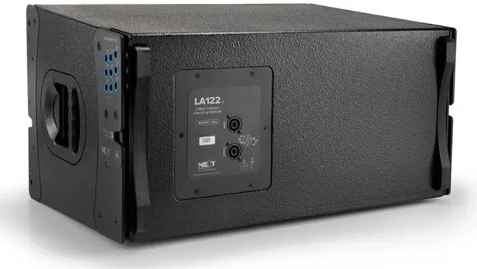
- The LA122vz/LA122Wv2 is part of the NEXT-proaudio LA series. It’s a compact line-array element that incorporates an impressive battery of high-technology features that enable it to achieve an unprecedented level of performance on compact line array systems.
- The LA122v2/LA122W2 incorporates a special 12″ low-frequency transducer employing a 75mm voice coil and neodymium magnet motor assembly. High frequency reproduction relies on the exceptional characteristics of two 1.4″ neodymium compression drivers designed for use in applications where high SPL and low distortion are required. A titanium diaphragm featuring a 65mm copper-clad, aluminium flat-wire voice coil yields high sensitivity, low distortion, and extended frequency response.
- The two HF drivers are loaded by a wave converter with path length equalization, the ICWG, that transforms the spherical waves into cylindrical isophasic waves, coupling seamlessly with the other high-frequency transducers of the array. For maximum flexibility, this line-array element is available in three different coverage angle configurations: 90° horizontal by 8° vertical (LA122v2), 120° horizontal by 8° vertical (LA122v2 + dispersion adaptor accessory, NC55126,) and 120° horizontal by 15° vertical (LA122Wv2). A combination of these two elements provides optimum vertical coverage for any application.
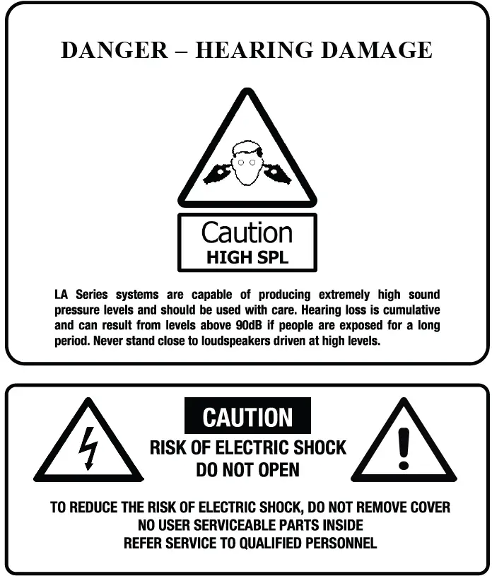
SAFETY FIRST
- Loudspeaker systems must be used safely.
- Please take some time to review the following points concerning the safe use of the NEXT LA122R/LA122W/2 line array element.
GROUND STACKING
- Always ensure that the floor or structure where the stack will be placed is even and can withstand the weight of the complete stack.
- Do not stack speakers too high, especially outdoors, where winds could topple the stack.
- Place cables in a way that they do not present a trip hazard.
- Do not place any objects on top of the stack; they can fall accidentally and cause injuries.
- Do not attempt to move the enclosures while connected.
Try not to operate the LA122v2/LA122Wv2 under heavy rain or moisture; it is weather-resistant but not completely “weather-proof”.
Do not expose the systems to extreme heat or cold conditions to prevent component damage.
RIGGING AND SUSPENSION
- Before rigging or suspending NEXT LA122v2/LA122W/2 systems, inspect all components and all hardware for any signs of damage or missing parts.
- If you find any damaged, corroded, or deformed parts, do not use them; replace them immediately.
- Do not use hardware that isn’t load rated or its rating is not enough to handle the system’s weight with a good safety factor (4 minimum). Don’t forget that the hardware won’t just hold the system’s weight. It has to be sturdy enough to handle dynamic forces like winds and others, without any part deformation. NEXT-proudio advises customers to contact a licensed, professional engineer regarding equipment installation.
- The next LA122v2/LA122Wv2 system installation should only be carried out by qualified personnel.
- Always use adequate protective clothing and equipment to prevent possible injuries.
- Only install the systems on solid, levelled ground and isolate the surrounding area during installation and operation, to prevent the general public’s presence near the systems.
- Be sure you understand all local and national regulations regarding equipment installation.
- Failure to comply with these instructions may result in injury or death.
CONNECTIONS AND ELECTRIC DIAGRAM
- The LA122v2 / LA122Wv2 is connected through Neutrik® SpeakON® NL4 plugs (not supplied). A wiring description is printed on the connection panels located on the back of the cabinet.
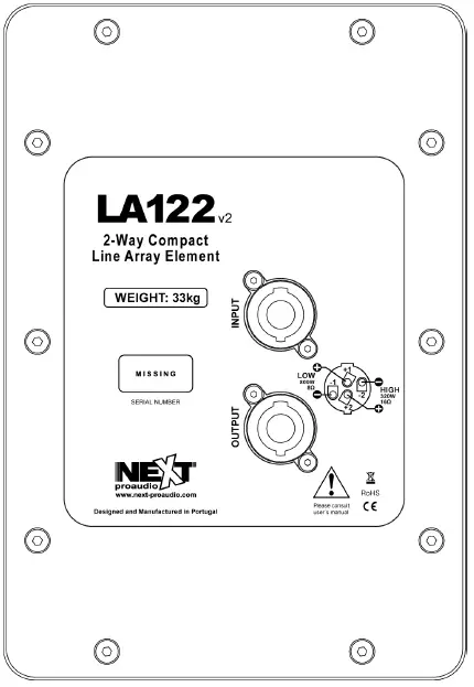
- The 4 pins of the two Neutrik® NL4 SpeakON® sockets are wired in parallel within the enclosure.
- Either connector can be used to connect to the amplifier or another LA122v2/LA122Wv2 element.
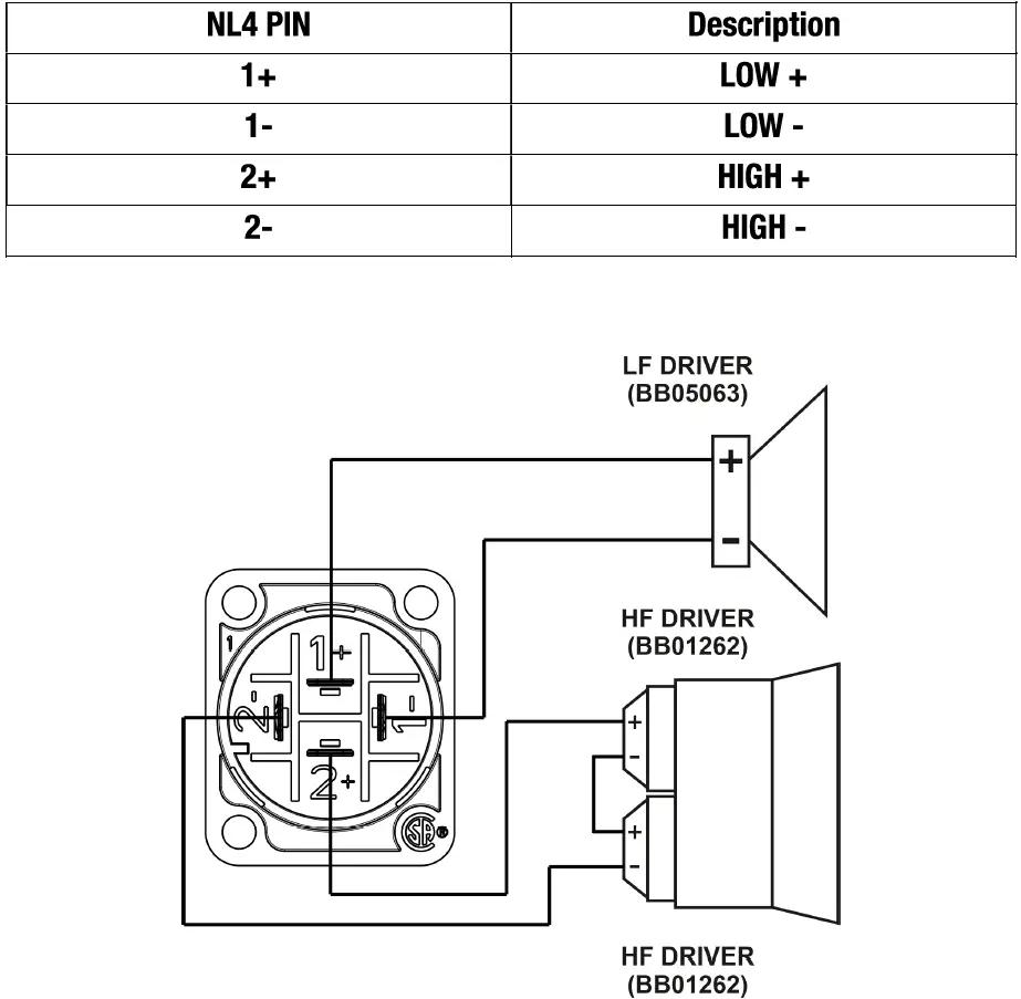
- Please note that the LA122v2/LA122Wv2 Line Array element is a two-way system. See the table and the diagram below:
AMPLIFICATION
- Normally, LA122vz systems are also supplied with NEXT-proudio power-rack mounts already configured for optimum performance, according to the configuration chosen by he customer.
- NEX-proudio recommends using only NEX-proaudio-approved amplifiers and signal processing units, and only provides signal processing configuration files for approved signal processing units.
WARNING – Be advised that due to some specific features and technologies employed on the LA122v2 element, you will damage the speakers if the wrong crossover configuration is employed.
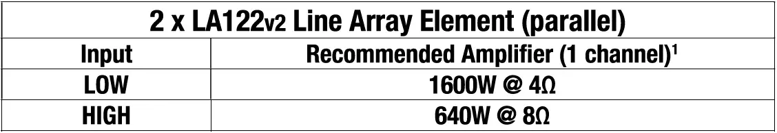
- The LA122v2/ LA122Wv2 element is a passive two-way system.
- The high frequency band is reproduced by two 1.4* drivers connected in series, having a combined nominal impedance of 160.
- The low-frequency band is reproduced by a single 12″ driver with 80 nominal impedance. See the table below for the recommended power amplifier power:
CABLE SELECTING
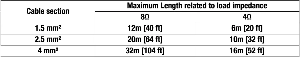
- Selecting a cable consists of calculating the correct cable section (size) in relation to the load impedance and the required cable length.
- A small cable section will increase its serial resistance, which will induce power loss and response variations (damping factor).
- The following table indicates, for 3 common sizes, a cable length with a maximum serial resistance equal to 4% of the load impedance (damping factor = 25):
RIGGING SYSTEM
- The LA122v2/ LA122Wv2 has a simple and intuitive four-point rigging system. It has 2 articulated joints on the front and 2 rear adjustable joints. The rear joints let you define the angle between two elements.
- The LA122vz is the main model. It will be the core of any LA122v2/LA122Wv2 system. It has a controlled 8° vertical dispersion, and its angle is adjustable from 0° to 8° relative to the upper element. LA122Wv2 is a wider dispersion element (15°), normally used as the last element on the array, pointing to the nearest public.
- In order to suspend a LA122v2/LA122Wv2, you’ll need to use the NEXT NC18124 frame. This suspension frame is built specifically to suspend the LA122v2/LA122Wv2 and/or LAs118v2 elements. It makes possible the suspension of up to 16 x LA122v2/LA122Wv2 elements.
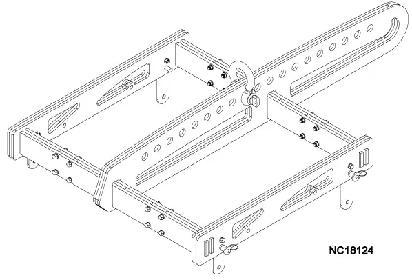
- You will also need the NEXT VP60052 lock pins.
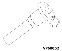
- Never use any lock pins but the ones supplied by NEXT-proudio. These pins are built to withstand the system’s weight with a good safety factor. They are also built with very specific dimensions. On the other hand, before you suspend the system, please read the instructions in the “Safety first” chapter.
- Let’s assemble a typical LA122 array system consisting of four LA122 with angle positioning of 0°, 2°, 4 °, 8° from top to bottom. After reading and understanding the “Safety first” chapter, follow the instructions below:
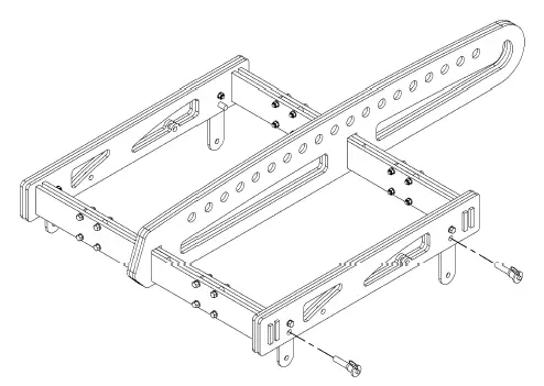
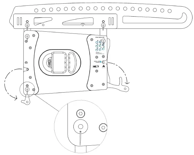
- Step 1 – Pull the frame’s swivel arms out of the parking position and insert a safety locking pin in each swivel arm locking position as shown in the image above. Verify that the locking pins are secured.
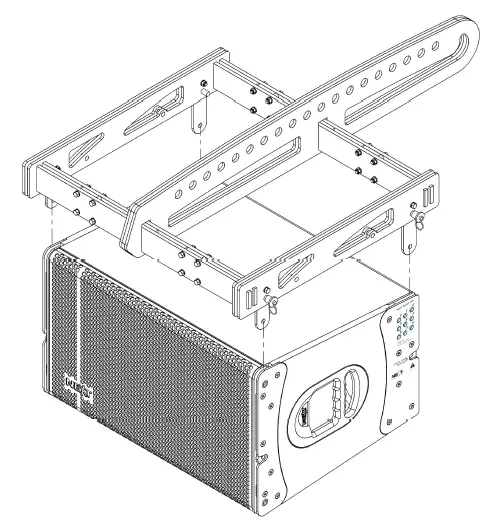
- Step 2 – With the swivel arms locked in place, align and insert them in the LA122v2 as shown above.

- Step 3 – Insert a locking pin on both front swivel arms first, then lift the frame at the back until the swivel arm is aligned with the 0° hole. Insert now lock pins at these holes on both sides of the element and verify they’re secure.
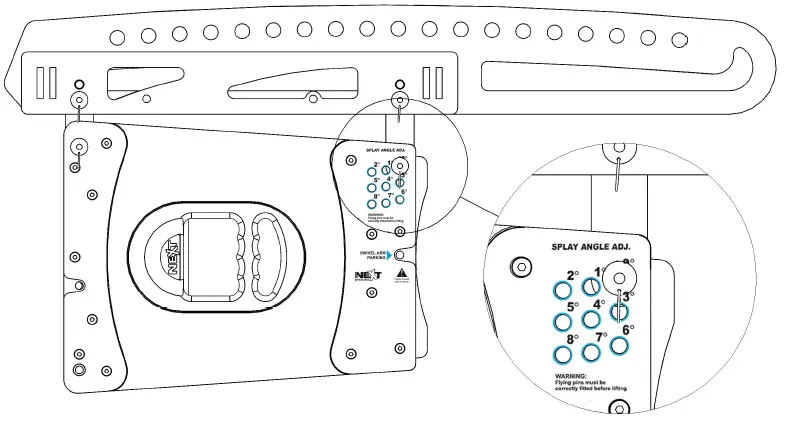
Attention
Between the Flying Frame and the first LA122vz, the splay can only be configured on the 0° position. If any initial inclination is needed, move the shackle to the appropriate hole on the centre bar.
Step 4 – Pull the LA122vz swivel arms out. On the front swivel arms, insert the locking pin. This will assure that the centre of rotation of the next element is fixed. Check if the locking pin is secured.
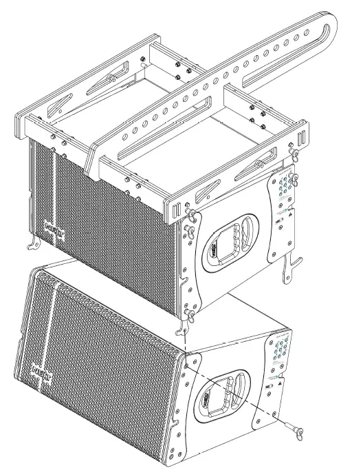
- Step 5 – Insert the next LA122 in the array starting with the front side and insert the front locking pins. Check if the locking pins are secured.
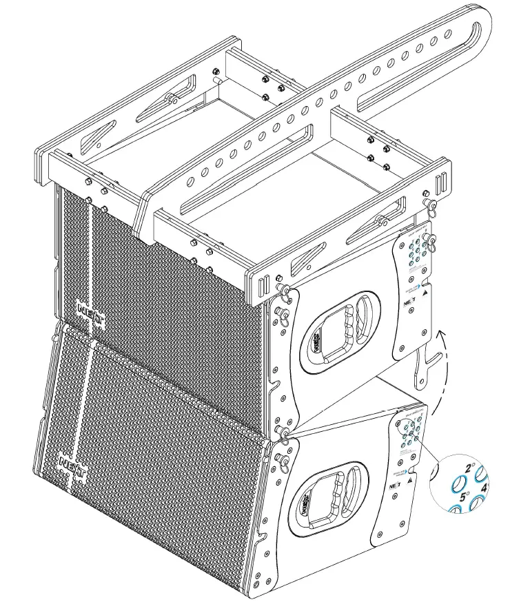
- Step 6 – With the front swivel arms locked in place, you can now rotate the element and, with the aid of e handles on the rear swivel arms, lock the element with a splay angle of 2°. Insert the locking pins and check that they are secured.
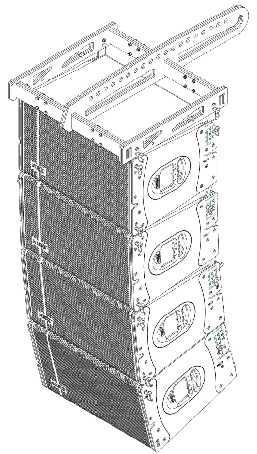
- Step 7 – Repeat steps 4 to 6 for the next two elements using the 4° and 8° splay angle adjustment positions, respectively.
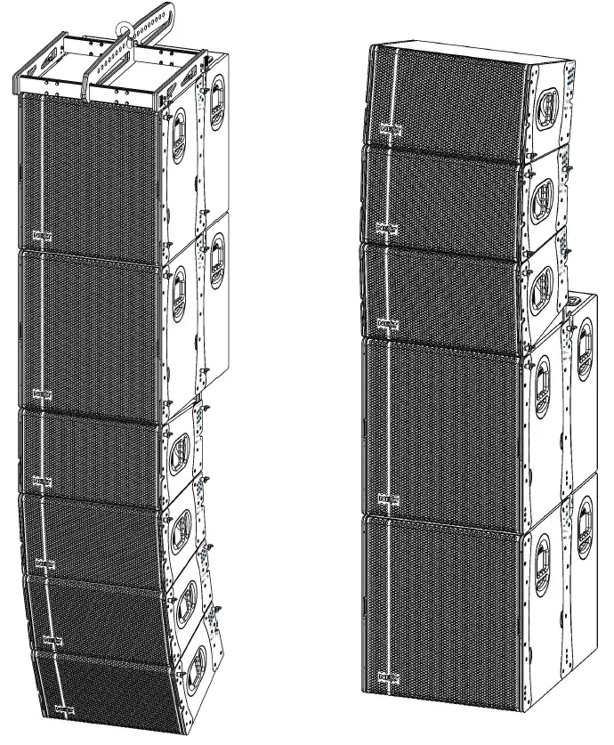
Here’s an image of the full system assembly:
- Also, some other configurations can be done using LA122vz and LAs118v2. The flying system is ready to attach subwoofers and full-range speakers on the same array.
- The mixed array, with subwoofers and full-range speakers, can be either flown or stacked.
- The left-most picture is a flown array. The right-most picture is a stacked array.
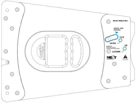
The LA122W2 is a little different from the LA122v2. The principle is the same, but instead of eight possible splay angles, it has only two splay positions, which differ according to the element that is mounted above it. When it is assembled below a LA1222, for example as a nearfield speaker, the position will be 11.5°. When coupled to another LA122Wz, the position will be 15°. We can see this information on the panels of the element as shown below.
TROUBLESHOOTING
Simple troubleshooting does not require sophisticated measurement equipment and can be easily undertaken by users. The technique should be to segment the system to identify the faulty system component: signal source, controller, amplifier, loudspeaker, or cable? Most installations are multi-channel. It is often the case that one channel works and others do not. Trying different combinations of system elements can usually help to isolate and locate the fault.
Some cabinet faults can be quite easily identified and corrected by the user. A simple sweep with a sine wave generator can be very helpful, though it MUST be made at a fairly low level to prevent damage to the speakers. A sine wave sweep can help find:
- Vibrations due to loose screws.
- Air-leak noises: check that no screws are missing, particularly where the accessories attach to the cabinet.
- Vibrations are due to a front grille badly positioned on the quick-release fixings.
- A foreign object that has fallen into the cabinet after repair or through the ports.
- Internal connection wires or absorbing material touching the loudspeaker diaphragm: check by removing the bass loudspeaker.
- Loudspeaker not connected or phase reversed following a previous inspection, test, or repair.
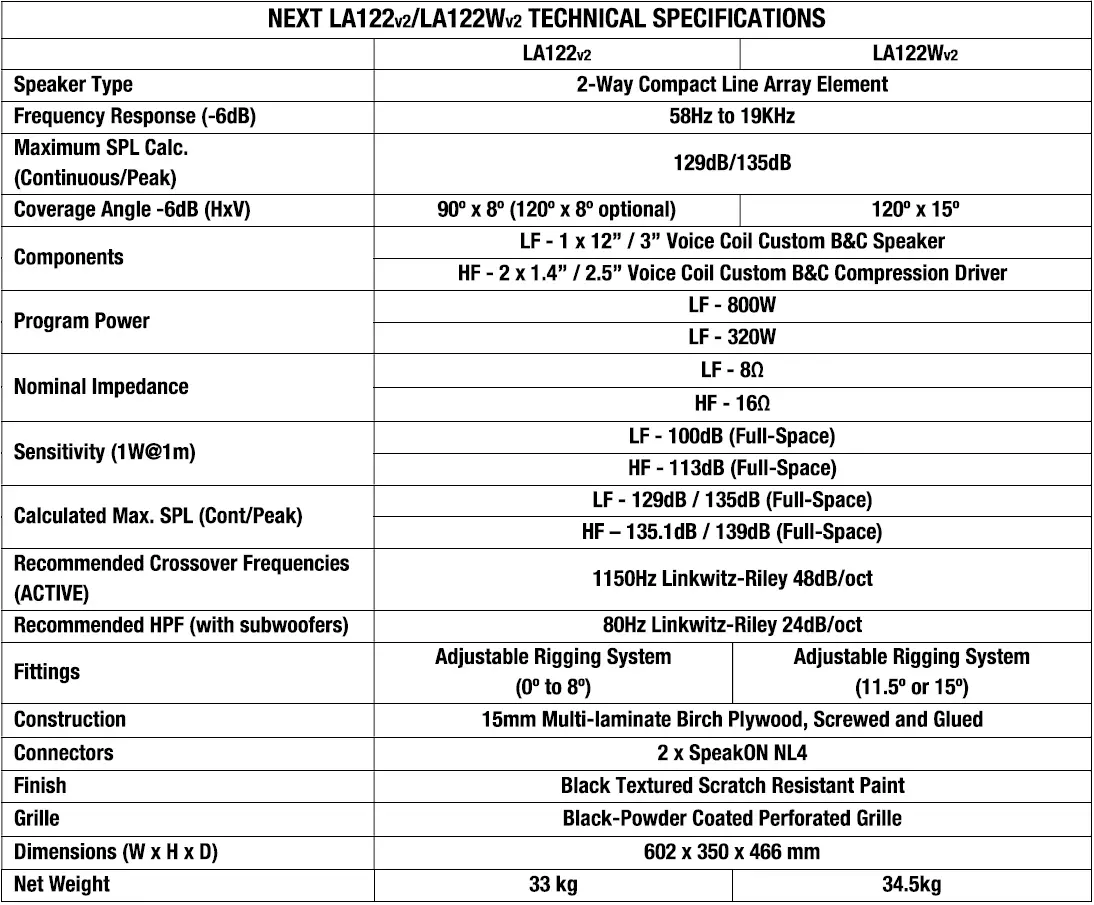
TECHNICAL SPECIFICATIONS
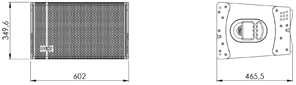
DIMENSIONS
WARRANTY
- NEXT-proudio’s products are warranted by NEXT-proudio against manufacturing defects in materials or craftsmanship over 5 years for the passive loudspeakers, and 2 years for all other products, counting from the date of original purchase. The original receipt of purchase is mandatory for warranty validation purposes, and the product must have been bought from a NEXT-proudio authorized dealer.
- The warranty can be transferred to a subsequent owner during the warranty period; however, this cannot extend the warranty period beyond the original warranty period of five years from the original date of purchase stated on the NEXT-proudio’s invoice.
- During the warranty period, NEXT-proudio will, at its discretion, either repair or replace a product which proves to be defective, provided that the product is returned in its original packaging, shipping prepaid, to an authorized NEXT-proudio service agent or distributor.
- NEXT-proudio cannot be held responsible for defects caused by unauthorized modifications, improper use, negligence, exposure to inclement weather conditions, acts of God or accident, or any use of this product that is not per the instructions provided by this manual and/or NEXT-proudio. NEXT-proaudio is not liable for consequential damages.
- This warranty is exclusive, and no other warranty is expressed or implied. This warranty does not affect your statutory rights.
CONTACTS
- In case of any doubts or any further information, just:
Write us:
- NEXT Audiogroup
- Rua da Venda Nova, 295
- 4435-469 Rio Tinto
- Portugal
Contact us:
- Tel. +351 22 489 00 75
- Fax. +351 22 480 50 97
Send an e-mail:
Search our website:
Follow us on:
- Facebook: facebook.com/nextproaudio
- Instagram: instagram.com/nextproaudio
- LinkedIn: linkedin.com/company/next-proaudio
- Twitter: twitter.com/next_proaudio
- YouTube: youtube.com/user/NEXTmanufacturer
FAQ
- Q: Where can I find more information about the NEXT LAs118v2?
- A: For details about the NEXT LAs118v2, please refer to the LAs118v2 manual or visit www.next-proaudio.com for additional information.
Documents / Resources
 |
next-pro audio LA122v2 2 Way Compact Line Array Element [pdf] User Manual LA122v2, LA122Wv2, LA122v2 2 Way Compact Line Array Element, LA122v2, 2 Way Compact Line Array Element, Line Array Element, Element |