newline DV-13524-PLUS All in One Direct View LED Display

Safety Instructions
- Please read this manual carefully and follow the instructions before use.
- Please complete the installation according to the installation methods provided in the user manual.
- Please cut off the power of the screen during installation and maintenance to prevent electric shock and injury, and avoid short circuit of the live parts of the PCB board against the metal frame. Do not place the front of the product on an irregular surface to avoid permanent damage to the display surface of the product.
- Do not place the product on a tilted or unstable table or pallet to prevent it from falling or tipping, which may cause permanent damage to the product.
- Do not place heavy objects on the power cord to avoid damaging the cable and causing electric shock or fire.
- Do not bend or move the power or data cables repeatedly to avoid damage and cause electric shock or fire.
- Please arrange, tie and fix the power cord and network cable orderly after the installation, and separate the strong and weak current.
- Please regularly clean the screen. If you have any questions about cleaning products, please contact customer service.
- Please use the screen in a well-ventilated environment.
- Do NOT expose the product to prolonged exposure or exposure to environments containing a large amount of dust, strong acidic or alkaline substances, as this may cause permanent damage to the product.
- DO NOT place fire or any device that gives off high heat around the display.
- Please use original Newline accessories. If you need to use self-purchased accessories, please consult customer service.
- Arrange professional personnel to inspect the screen regularly.
Important Warning
- Warning: Electric shock hazard.
Danger of high voltage, Non-professionals are prohibited from opening the panel. It is forbidden to plug and unplug the power cord under working conditions. - Warning: DANGER OF PERSONAL CASUALTIES.
It is necessary to take corresponding protective measures for high-altitude operators to avoid accidents. - Warning: KEEP AWAY FROM FLAMMABLES AND/OR EXPLOSIVES.
Keep the screen away from flammables and explosives. - Attention: STAY AWAY FROM THE AIRCONDITIONING VENT.
Keep away from the air outlet of the air conditioner and keep the screen dry. - Attention: PAY ATTENTION TO SCREEN GROUNDING.
Class I equipment, EQUIPMENT, grounding treatment is required. - Attention: POWER ON REGULARLY.
When not in use for a long time, turn on the screen power regularly to extend the product’s service life.
LED display screens cannot be turned off for a long time. In high-humidity environments, if the screen has not been used for more than 3 days, it is necessary to check and confirm whether there is water vapor on the surface of the screen before turning it on. If there is moisture, ventilation or dehumidification is necessary. When lighting the screen, preheating and lighting method should be used: turn on the screen for 2 hours with black color, preheat 10-20% brightness for 4-8 hours, and then adjust to normal use brightness (40% -80%) to light the screen, in order to eliminate moisture and avoid abnormalities during use (the normal use brightness can be adjusted by the user according to the usage environment).
Attention: POWER SUPPLY.
When wiring power supply, please pay attention to load balance, overload is strictly prohibited. Before installation, please ensure that the operating voltage of the display is suitable for the local grid voltage.
Unpacking
Please note the following when unpacking:
- Do Not discard the original packaging material. Please keep the original packaging materials for use during new transportation.
- Keep your documents in a safe place. This document is required for commissioning the device. It is also needed when presenting the equipment for debugging, and is part of the device.
- Check the delivered device for any obvious damage during transportation.
- Verify that the goods shipped contains the complete device and accessories you ordered separately.
- If there is any discrepancy or damage during transportation, please contact customer service. The product should not be exposed to the installation site under construction for a long time after unpacking.
Safety Code
- Non-professionals are not allowed to disassemble the product without permission to avoid electric shock of high voltage.
- Please consult the local power supply operator if not clear about the local grid voltage.
- Personnel working at heights shall be provided with safety protections.
- The frame structure of LED display should be designed and constructed by professionals.
- Make sure to take safety measures for grounding the equipment.
Warning Signs
Preventive measures:
For your personal safety and to avoid unnecessary property damage, it is important to pay attention to the prompts in this manual. The reminder for personal safety is indicated by . And the reminder only related to property damage does not include a warning triangle. The warning reminder varies from high to low according to the level of danger, as follows:
Danger: Failure to take appropriate protective measures may result in death or serious personal injury.
Caution: Failure to take appropriate protective measures may result in minor personal injury.
Attention: If corresponding protective measures are not taken, it may lead to unexpected results.
Documentation
Scope of application of this document: This article is applicable to Newline DV One +.
Copyright Notice
Newline reserves the right to make changes to this product manual without prior notice. We are not responsible for any direct, indirect, intentional or unintentional damages or hidden dangers caused by not following the product manual for installation or improper use.
The ownership of other trademarks involved in this manual belongs to the corresponding product manufacturers.
Product Overview
Appearance and Introduction
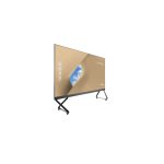
This product is shown in the following figure. Some features have been simplified.
Front View

Rear View

No. Part Name Description
- Front key Control the LED display
- Mobile stand A movable bracket for support structure
- Wall-Mounted A bracket for support structure
- Wi-Fi Module Provide the wireless network
- Power Input Power supply
- Rear Interface(Up) Connecting the external device
- Rear Interface(Side) Connecting the external device
Notes
The product images shown are for illustration purposes only and may not be an exact representation of the product.
Keys and Interfaces Introduction
Front key


Rear Interface

No. Name Function Description
- HDMI IN interface Used for connecting external video sources
- USB 2.0 Type-B Used for connecting to USB device
- Type C/w PD interface Used for Audio/video input, data, USB drive, supports 65W charging
- USB3.0 interface Used for connecting to USB device

No. Name Function Description
- S/PDIF output interface Used for connecting to fiber optic speaker
- Line output interface Used for connecting to 3.5mm audio output devices
- RJ45 network interface Used for networking
- HDMI OUT interface Used for video output, 1080p mode
- RS232 interface Used for achieving centralized control
- HDMI 2(ARC) interface Used for external device video access
- USB3.0 interface Used for connecting to USB device
Remote Control Introduction

Air mouse pairing
First-time use requires Bluetooth pairing between the DV One+ and the remote control:
- Hold the volume – and brightness – buttons simultaneously for 5 seconds to enter pairing mode; the remote control indicator light will flash;
- Search for DYC-Q5 in the initial pairing page or Setting > Network > Bluetooth for pairing.
Installation Guide
Before installing, please carefully read the following safety precautions and formulate strict safety assurance measures to ensure construction safety.
Precautions
Attention
- After the product is unpacked, please check whether the product is damaged.
- At least two people are required to participate in the installation process to ensure safety.
- Please take necessary measures to prevent the product from falling during installation. Operators shall use safety belts and helmets correctly when working at heights.
- Ensure that the bracket and support beam of the LED display screen are horizontal.
- Be careful not to drop objects on the LED display screen.
- It is strictly forbidden to install in the environment where iron filings, wood shavings and paint are produced.
- Please install this product in a relatively safe environment (avoid installation under a large amount of dust, strong acid, strong alkaline or diffuse paint).
- Do not leave screws, nuts and other metals in the box during the installation process to prevent short circuit when the screen is working.
- When moving the cabinet, please do not touch the LED and take anti-static measures to prevent static electricity from damaging the LED or IC device.
- Please be careful to prevent the LED panel surface from colliding or being compressed
Unpacking
Please note the following when unpacking:
- Do Not discard the original packaging material. Please keep the original packaging materials for use during new transportation.
- Keep your documents in a safe place. This document is required for commissioning the device. It is also needed when presenting the equipment for debugging, and is part of the device.
- Check the delivered device for any obvious damage during transportation.
- Verify that the goods shipped contains the complete device and accessories you ordered separately. If there is any discrepancy or damage during transportation, please contact customer service.
- The product should not be exposed to the installation site under construction for a long time after unpacking.
Wall-mounted Installation
Installation Dimensions


Installation Steps
LED display supports both wall mounting and mobile bracket installation. The following is an example of wall mounting for details. If you choose mobile bracket mounting, please follow the mobile bracket mounting instructions to assemble the mobile bracket first, and then start assembling the LED display according to the third step.

- Connecting the wall-mounting bracket
Use A1 hexagon socket bolts and the B1 connector to attach the upper wall-mounting bracket, and then use the same method to attach the lower wall-mounting bracket.
Show the final assembly diagram Upper wall-mounting bracket
 lower wall-mounting bracket
- Fixing the wall mount bracket to the wall
- Mark the hole positions on the wall according to the dimensions shown in the diagram, and drill holes (diameter 12mm, depth 60mm).
- Insert the A3 expansion plugs into the drilled holes, ensuring that the plugs do not protrude from the wall.
- Finally, secure the wall mount brackets with A2 expansion screws. Make sure that the upper and lower wall brackets are aligned on the left and that the vertical distance between the two wall brackets is 1377mm.
Note:
The lower mounting bracket must not be less than 280 mm above the ground.
The upper mounting bracket shall have a clearance of 450 mm above and 400 mm to the right
- Hanging the cabinet to the bracket
Starting with the middle two columns (C and D) by hanging them on the wall mount brackets, ensuring that the slots on the back of the cabinets fit perfectly onto the brackets. Next, hang the B and E columns, and finally, hang the A and F columns.
Be sure to connect the power cord (see reference diagram below) before hanging the F-column cabinet (with pull-out box): Load-bearing Screws
Make sure that the load-bearing screws snap into the notches of the wall bracket.
- Secure the Square Connector
Take one set of the B2 Square Connector and install it at the cabinet joint (as shown in the diagram). Secure them with A4 Hexagon socket bolts. Adjust the tightness of the bolts to ensure that the cabinet are installed flat. Repeat this process for all the cabinets.
- Assemble the cabinet
Insert the A5 Hexagon socket bolts from right to left into the connection between the two cabinets, and then tighten them with a wrench. Ensure that the adjacent cabinets are flush, as shown in the diagram. After completing the cabinet installation, use two A9 Hexagon socket bolts to lock the ends of the upper wall bracket.
- Connect the cables
The cables inside each individual cabinet are pre-connected at the factory. You only needs to connect the cables left outside in sequence to the bottom row (A1-F1) of the cabinet.
- Step 1. Connecting the network cables to the left network ports:
Network Cable 1 connects to Column F1;
Network Cable 2 connects to Column E1;
Network Cable 3 connects to Column D1;
Network Cable 4 connects to Column C1;
Network Cable 5 connects to Column B1;
Network Cable 6 connects to Column A1.
- Step 2. Connect the relay wires, numbered No. 1-6, to the connectors of the F1-A1 cabinet in sequence
Relay wires No. 1 connects to Column F1;
Relay wires No. 2 connects to Column E1;
Relay wires No. 3 connects to Column D1;
Relay wires No. 4 connects to Column C1;
Relay wires No. 5 connects to Column B1;
Relay wires No. 6 connects to Column A1.
- Step 3. Connect the power lines, numbered Line 1-6, to the F1-A1 cabinet in sequence:
Connecting the brown wire to the IN 1 terminal;
Connecting the blue wire to the IN 2 terminal;
- Connecting the yellow-green ground wire to the ground of the cabinet.
- Step 1. Connecting the network cables to the left network ports:
- Assemble the lower frame
On the key board on the inside of the lower frame, access the keypad cable and then stuff all the cables into the lower frame, do not jam or pinch the cables.
* Pay particular attention: The cables must not be bent or pinched by the frame. Secure the lower frame using A6 Hexagon socket bolts from top to bottom. Secure the lower-right frame first, then the lower-left frame, ensuring that the installation is flush.
- Frame Pre-treatment
Take the A7 ball plunger and push them into the slots on the inside of the frame, put 6 ball plungers in each of the left and right frames and 3 ball plungers in each of the two upper frames.
Move the ball plungers near to the screw hole marks marked by the lines as shown in the diagram. Next, insert the corner covers into the left side of the upper left frame and the right side the upper right frame, as indicated by the figure.
- Install the Frame
First, take the left and right frame, adjust the position of the Ball Plunger and push it into the cabinet to make the frame fits into the cabinet.
Then, take the top frame and press the corner cover into the slots of the side frame. Finally, secure the left frame, the right frame and the top frame from the inside of the cabinet outward with A8 Hexagon socket bolts.
- LED Panel Installation
Install the LED panels on the cabinet according to the module number diagram and the corresponding numbers on the cabinet, ensuring that the surface is flat and the gaps are minimal. Explanation of LED Panel Module Numbering:- The first character (X) represents the sequence number of the complete screen in the batch work order.
- The second character (A, B, C, D, E, F) represents the column number.
- The third character (1, 2, 3, 4, 5, 6) represents the row number.
- The fourth character (1, 2, 3, 4) represents the LED panel number.
The labels on the packaging of each set of four LED panel modules should match the labels on the individual cabinets. The labels on the packaging for each column of LED panels should correspond to the column numbers: XA, XB, XC, etc.
LED Panel Module Number
| A | B | C | D | E | F | ||||||
| xA6-3 | xA6-4 | xB6-3 | xB6-4 | xC6-3 | xC6-4 | xD6-3 | xD6-4 | xE6-3 | xE6-4 | xF6-3 | xF6-4 |
| xA6-1 | xA6-2 | xB6-1 | xB6-2 | xC6-1 | xC6-2 | xD6-1 | xD6-2 | xE6-1 | xE6-2 | xF6-1 | xF6-2 |
| xA5-3 | xA5-4 | xB5-3 | xB5-4 | xC5-3 | xC5-4 | xD5-3 | xD5-4 | xE5-3 | xE5-4 | xF5-3 | xF5-4 |
| xA5-1 | xA5-2 | xB5-1 | xB5-2 | xC5-1 | xC5-2 | xD5-1 | xD5-2 | xE5-1 | xE5-2 | xF5-1 | xF5-2 |
| xA4-3 | xA4-4 | xB4-3 | xB4-4 | xC4-3 | xC4-4 | xD4-3 | xD4-4 | xE4-3 | xE4-4 | xF4-3 | xF4-4 |
| xA4-1 | xA4-2 | xB4-1 | xB4-2 | xC4-1 | xC4-2 | xD4-1 | xD4-2 | xE4-1 | xE4-2 | xF4-1 | xF4-2 |
| xA3-3 | xA3-4 | xB3-3 | xB3-4 | xC3-3 | xC3-4 | xD3-3 | xD3-4 | xE3-3 | xE3-4 | xF3-3 | xF3-4 |
| xA3-1 | xA3-2 | xB3-1 | xB3-2 | xC3-1 | xC3-2 | xD3-1 | xD3-2 | xE3-1 | xE3-2 | xF3-1 | xF3-2 |
| xA2-3 | xA2-4 | xB2-3 | xB2-4 | xC2-3 | xC2-4 | xD2-3 | xD2-4 | xE2-3 | xE2-4 | xF2-3 | xF2-4 |
| xA2-1 | xA2-2 | xB2-1 | xB2-2 | xC2-1 | xC2-2 | xD2-1 | xD2-2 | xE2-1 | xE2-2 | xF2-1 | xF2-2 |
| xA1-3 | xA1-4 | xB1-3 | xB1-4 | xC1-3 | xC1-4 | xD1-3 | xD1-4 | xE1-3 | xE1-4 | xF1-3 | xF1-4 |
| xA1-1 | xA1-2 | xB1-1 | xB1-2 | xC1-1 | xC1-2 | xD1-1 | xD1-2 | xE1-1 | xE1-2 | xF1-1 | xF1-2 |
Notes
After the installation of the LED Panel, if there is a gap or segment difference, you can adjust the screws on the cabinet (corresponding position) to adjust the height of the LED Panel.
LED Display Panel Maintenance
This product supports front LED panel maintenance. The tool required for front maintenance is a suction cup, as shown below:

The front maintenance process as follows:
- Step 1: Place the suction cup on the surface of the LED panel(Turn off the power supply for the LED display first);
- Step 2: Pull up the handle, make sure the light board is sucked by the suction cup;
- Step 3: Pull out the suction cup towards you. Protect the light board with your other hand.Notes: Make sure that the module does not touch the adjacent modules when pulling , so as to avoid collision and damage to the other modules or LEDs.
- Step 4: Move the LED module to a safe place, and ensure that it is placed on the original foam pads or another soft,flat surface to prevent scratches or other damage to the module or the LEDs.
- Step 5: Pull the handle on the suction cup down to release the LED Module.


Installing the Wi-Fi Module
CAUTION
Wi-Fi Module does not support hot plugging. Therefore, you must insert or remove the Wi-Fi Module when the display is powered off. Otherwise, the LED display or Wi-Fi Module may be damaged.
Perform the following steps to install the Wi-Fi Module.
- Step 1: Unscrew the 2 screws on the Wi-Fi Module port and remove the shielding cover.

- Step 2: Insert the Wi-Fi Module into the port on the rear of the LED display until firmly seated, using the 2 screws to secure it.


Pull-out drawer maintenance
CAUTION
Unless there is a motherboard problem that makes the machine unusable, it is not recommended to pull out the pull-out drawer without permission to avoid damage to the core original parts affecting the use of the whole machine.
- Step 1: Unscrew the screws on the pull-out drawer;

- Step 2: Pull the handle to pull out the pull-out drawer.

Power On/Off
Power On
- Ensure the two power cables are fully seated into the LED display and wall outlet before powering on the LED display.
 Notes
Notes
The power outlet should be installed near the LED display and should be easily accessible. - Press the power button
 on the front panel or
  on the remote control.

Power Off
- Press the power button on the front display or the power button on the remote control and a Warning dialog box will be displayed as shown in the following figure.

- In the Warning dialog box, use the remote control to select Power off to turn off the display, and the power indicator will turn to red. Tap the power button to switch the icon, long press the power button for 3 seconds to confirm the selection.
If you want to completely turn off the LED display, unplug the two power cords.
LD Notes
- Please properly shut down the LED display before disconnecting the power source or it may cause damage. An accidental power failure may cause damage to the LED display.
- Do not repeatedly turn the power on & off in a short period of time as it may cause malfunction.
For More Information
Please visit our website https://newline-interactive.com and select your regional website. Once there, navigate to the Support section and click on Downloads to download the User Manual for detailed instructions.
Contact Us for Support
Please directly contact the support team within your region.
USA
Hotline: +1 833 469 9520
Email: support@newline-interactive.com
Frequently Asked Questions
- Q: Can non-professionals open the panel of the device?
A: No, non-professionals are prohibited from opening the panel due to the risk of electric shock. Only professionals should handle such tasks. - Q: What should I do if the screen is near flammables or explosives?
A: Keep the screen away from flammable and explosive materials to prevent any potential hazards. - Q: How often should I power on the device if not in use for a long time?
A: It is recommended to regularly turn on the screen power when not in use for an extended period to prolong the product’s service life.
Documents / Resources
 |
newline DV-13524-PLUS All in One Direct View LED Display [pdf] User Guide DV-13524-PLUS, DV-13524-PLUS All in One Direct View LED Display, DV-13524-PLUS, All in One Direct View LED Display, Direct View LED Display, View LED Display, LED Display |