Netzer Precision VLP-247 Hollow Shaft Rotary Encoder Kit Encoder
Specifications
- Angular resolution: 18-20 bit
- Nominal position accuracy: ±0.006°
- Maximum operational speed: 4,000 rpm
- Measurement range: Single turn, unlimited
- Rotation direction: Adjustable CW/CCW*
- Built In Test BIT: Optional
- * Default same direction from bottom side of the encoder
Product Information
The VLP-247 Absolute Hollow Shaft Rotary Encoder Kit Encoder is a precision encoder designed for harsh environment applications. Based on capacitive technology developed by Netzer Precision Position Sensors, this encoder is built to meet the requirements of demanding applications.
Product Usage Instructions
Mechanical Mounting
Refer to the Mechanical Mounting section in the user manual for detailed instructions on mounting the encoder. Follow the End-of-Shaft Installation guidelines for proper installation.
Operational Mode
The encoder operates in SSi / BiSS mode. Please refer to the user manual for specific instructions on configuring and operating the encoder in these modes.
FAQ
- Q: What is the maximum operational speed of the VLP-247 encoder?
A: The maximum operational speed of the VLP-247 encoder is 4,000 rpm. - Q: How long has the capacitive technology used in the VLP series been developed?
A: The capacitive technology used in the VLP series has been developed and improved for over 20 years by Netzer Precision Position Sensors.
VLP Encoders Introduction
Designed to meet the requirements of the most demanding applications
The VLP series of Electric Encoders™ are a line of encoders designed for harsh environment applications. These encoders are based on capacitive technology which have been developed and improved for over 20 years by Netzer Precision Position Sensors.
The VLP encoders are characterized by the following features that sets them apart from other similar encoders:
- Low profile
- Hollow shaft (Stator / Rotor)
- No bearings or other contact elements
- High resolution and excellent precision
- Immunity to magnetic fields
- High tolerance to temperature extremes, shock, moisture, EMI, RFI
- Very low weight
- Holistic signal generation and sensing
- Digital interfaces for absolute position
The holistic structure of the VLP Electric Encoder™ makes it unique. Its output reading is the averaged outcome of the entire circumference area of the rotor. This inherent design characteristic provides the VLP encoder with outstanding precision as well as a tolerant mechanical mounting. The absence of components such as ball bearings, flexible couplers, glass discs, light sources & detectors, along with very low power consumption, enables the VLP encoders to deliver virtually failure-free performance.
Technical Specifications
General
| Angular resolution | 18-20 bit |
| Nominal position accuracy | ±0.006° |
| Maximum operational speed | 4,000 rpm |
| Measurement range | Single turn, unlimited |
| Rotation direction | Adjustable CW/CCW* |
| Built In Test BIT | Optional |
* Default same direction from bottom side of the encoder
Mechanical
| Allowable mounting eccentricity | ±0.1 mm |
| Allowable axial mounting tolerance | ±0.3 mm |
| Rotor inertia | 876,053 gr · mm2 |
| Total weight | 220 gr |
| Outer Ø / Inner Ø / Height | 247 / 171 / 9 mm |
| Material (stator / rotor) | FR4 |
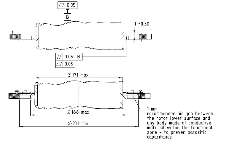
| Nominal air gap (stator, rotor) | 1 mm |
Electrical
| Supply voltage | 5V ± 5% |
| Current consumption | ~90 mA |
| Interconnection | Cable (standard 250mm) |
| Communication | SSi, BiSS-C |
| Serial output | Differential RS-422 |
| Clock frequency | 0.1-5.0 MHz |
| Position update rate | 35 kHz (Optional – up to 375 kHz) |
Environmental
| EMC | IEC 6100-6-2, IEC 6100-6-4 |
| Operating temperature | -40°C to +105°C |
| Storage temperature | -55°C to +125°C |
| Relative humidity | 98% Non condensing |
| Shock endurance / functional | 100g 6msec saw-tooth per IEC 60068-2-27:2009 40g 11msec saw-tooth per MIL-810G |
| Vibration functional | 7.7grms @ 20 to 2000 Hz per MIL-810G Category 24 |
| Protection | IP 40 |
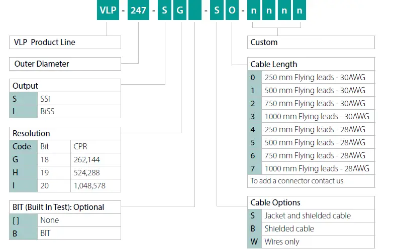
Ordering Code
Mechanical Drawings
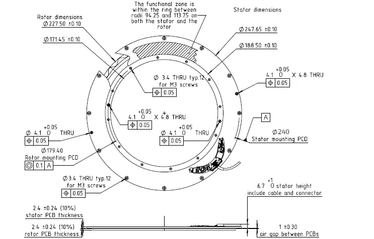
Unless otherwise specified
- Dimensions are in: mm Surface finish: N6
Linear tolerances
- 0.5-4.9: ±0.05 mm 5-30: ±0.1 mm
- 31-120: ±0.15 mm 121-400: ±0.2 mm
Mechanical Interface Control Drawing
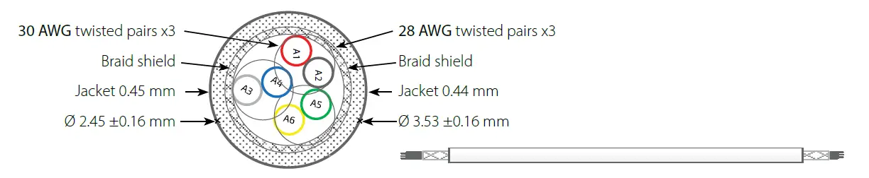
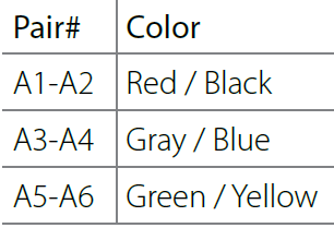
Cable options
| Netzer Cat No. | CB 00014 | CB 00034 |
| Cable type | 30 AWG twisted pair x 3 | 28 AWG twisted pair x 3 |
| Wire type | 2 x 30 AWG 25/44 tinned copper Insulation: PFE Ø 0.15 OD: Ø 0.6 ± 0.05 mm |
2 x 30 AWG 40/44 tinned copper Insulation: PFE Ø 0.12 OD: Ø 0.64 ± 0.05 mm |
| Temp. Rating | -55°C to +150°C | |
| Braided shield | Thinned copper braided 95% min. coverage | |
| Jacket | 0.45 silicon rubber (NFA 11-A1) | 0.44 silicon rubber (NFA 11-A1) |
| Diameter | Ø 2.45 ± 0.16 mm | Ø 3.53 ± 0.16 mm |
Storage and Handling
- Storage temperature: -55°C to +125°C
- Humidity: Up to 98% non-condensing
ESD Protection
As usual for electronic circuits, during product handling do not touch electronic circuits, wires, connectors or sensors without suitable ESD protection. The integrator / operator shall use ESD equipment to avoid the risk of circuit damage.
 ATTENTION OBSERVE PRECAUTIONS FOR HANDLING ELECTROSTATIC SENSITIVE DEVICES
Product Overview
Overview
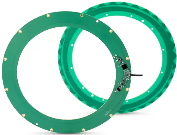
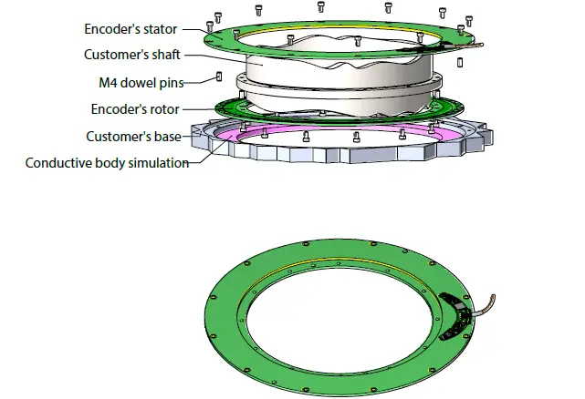
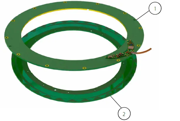
The VLP-247 absolute position Electric Encoder™ is a rotary position sensor developed for demanding applications. Currently it performs in a broad range of applications, including defense, homeland security, medical robotics and industrial automation. The Electric Encoder™ non-contact technology provides accurate position measurement through the modulation of an electric field. The VLP-247 Electric Encoder™ is a kit-encoder, i.e., its rotor and stator are separate.
- Encoder stator
- Encoder rotor
Unpacking – standard order
The package of the standard VLP-247 contains the encoder Stator & Rotor.
Optional accessories:
- CNV-0003, RS-422 to USB converter (with USB internal 5V power supply path).
- NanoMIC-KIT-01, RS-422 to USB converter. Setup & Operational modes via SSi /BiSS interface.
- RJ VLP-247 rotary jig
- DKIT-VLP-247-SG-S0, Mounted SSi encoder on rotary jig, RS-422 to USB converter and cables.
- DKIT-VLP-247-IG-S0, Mounted BiSS encoder on rotary jig, RS-422 to USB converter and cables.
Installation flow chart
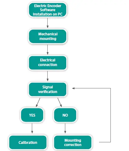
Electric Encoder Software Installation
The Electric Encoder Explorer (EEE) software:
- Verifies correct mounting for an adequate signal amplitude
- Calibration of offsets
- General set up and signal analysis
This section describes the steps associated with installing the EEE software application.
Minimum requirements
- Operating system: MS windows 7/ 10, (32 / 64 bit)
- Memory: 4MB minimum
- Communication ports: USB 2
- Windows .NET Framework, V4 minimum
Installing the software
- Run the Electric Encoder™ Explorer file found on Netzer website: Encoder Explorer Software Tools
- After the installation you will see Electric Encoder Explorer software icon on the computer desktop.
- Click on the Electric Encoder Explorer software icon to start.
Mechanical Mounting
Encoder mounting – End-of-Shaft Installation
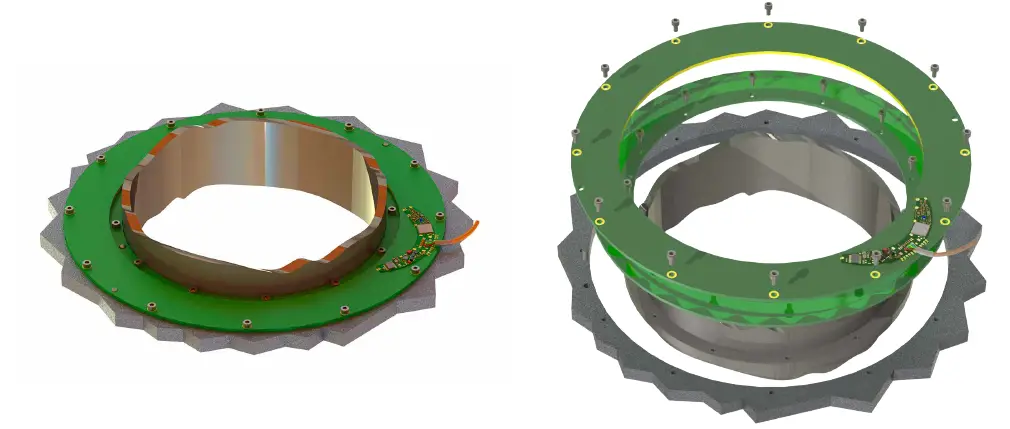
Typical encoder installation uses
- Mounting screws Socket Head Cup Screw 12xM2, 6 each per stator & rotor.
- Mounting dowel pins 4xØ2, 2 each per stator & rotor (not included with the encoder).
Encoder stator / Rotor relative position
For proper performance the air gap should be 1 mm ±0.3 mm
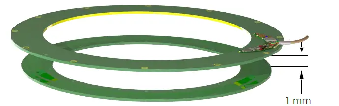
In an optimal mounting, the signal amplitude values generated by the encoder, would be in the middle of the range of the signal plot shown in the Encoder Explorer software (see plot below). This may vary according to the encoder type. Verify proper rotor mounting with the Encoder Explorer tools “Signal analyzer” or “Signal verification process.”
Note: for more information please read section 7
Electrical Connection
This chapter reviews the steps required to electrically connect the encoder with digital interface (SSi or BiSS-C).
Connecting the encoder
The encoder has two operational modes:
Absolute position over SSi or BiSS-C
This is the power-up default mode
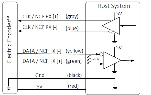
SSi / BiSS interface wires color code
| Clock + | Grey | Clock |
| Clock – | Blue | |
| Data – | Yellow | Data |
| Data + | Green | |
| GND | Black | Ground |
| +5V | Red | Power supply |
SSi / BiSS output signal parameters
| Output code | Binary |
| Serial output | Differential RS-422 |
| Clock | Differential RS-422 |
| Clock frequency | 0.1- 5.0 MHz |
| Position update rate | 35 kHz (Optional – up to 375 kHz) |
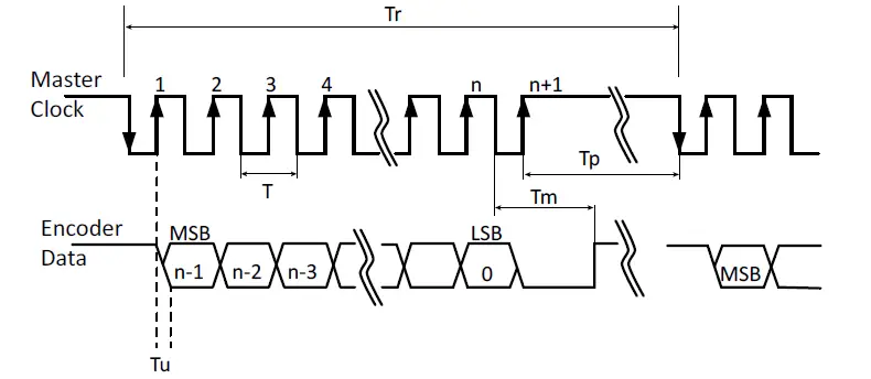
Digital SSi Interface
Synchronous Serial Interface (SSi) is a point to point serial interface standard between a master (e.g. controller) and a slave (e.g. sensor) for digital data transmission.
Built In Test option (BIT)
The BIT indicates critical abnormality in the encoder internal signals.
‘0’ – the internal signals are within the normal limits, ‘1’ – Error
The Part Number of the encoder indicates whether the encoder includes BIT. If no BIT is indicated in the PN, there is no additional error bit.
| Description | Recommendations | |
| n | Position resolution | 12-20 |
| T | Clock period | |
| f= 1/T | Clock frequency | 0.1-5.0 MHz |
| Tu | Bit update time | 90 nsec |
| Tp | Pause time | 26 – ∞ μsec |
| Tm | Monoflop time | 25 μsec |
| Tr | Time between 2 adjacent requests | Tr > n*T+26 μsec |
| fr=1/Tr | Data request frequency |
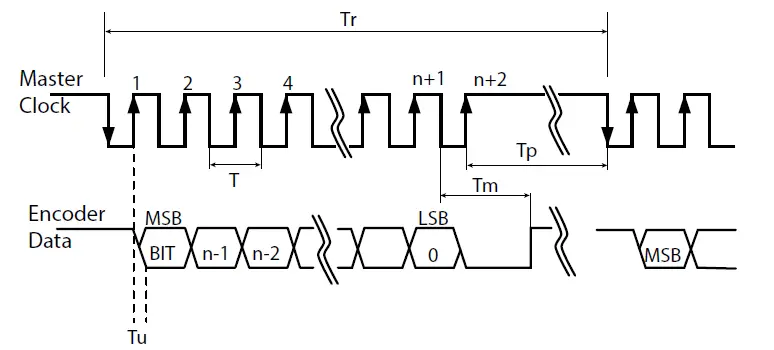
Digital BiSS-C Interface
BiSS – C Interface is unidirectional serial synchronous protocol for digital data transmission where the Encoder acts as “slave” transmits data according to “Master” clock. The BiSS protocol is designed in B mode and C mode (continuous mode). The BiSS-C interface as the SSi is based on RS-422 standards.
Built In Test option (BIT)
The BIT indicates critical abnormality in the encoder internal signals.
‘1’ – the internal signals are within the normal limits, ‘0’ – Error
The Part Number of the encoder indicates whether the encoder includes BIT. If no BIT is indicated in the PN, the error bit is always 1.
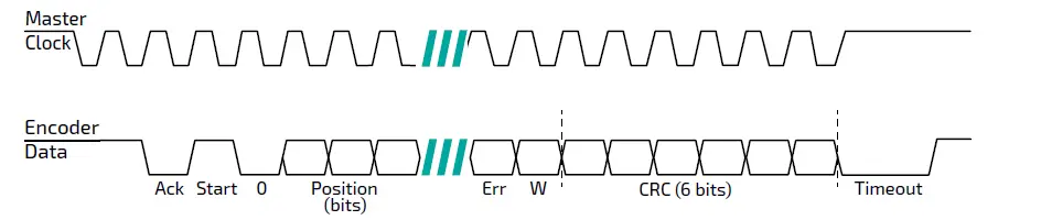
| Bit allocation per encoder-resolution | Description Default | Length | |||||
| 17bit | 18bit | 19bit | 20bit | ||||
| 27 | 28 | 29 | 30 | Ack | Period during which the encoder calculates the absolute position, one clock cycle | 0 | 1/clock |
| 26 | 27 | 28 | 29 | Start | Encoder signal for “start” data transmit | 1 | 1 bit |
| 25 | 26 | 27 | 28 | “0” | “Start” bit follower | 0 | 1 bit |
| 8…24 | 8…25 | 8…26 | 8…27 | AP | Absolute Position encoder data | Per resolution | |
| 7 | 7 | 7 | 7 | Error | BIT (Built In Test option) | 1 | 1 bit |
| 6 | 6 | 6 | 6 | Warn. | Warning (non active) | 1 | 1 bit |
| 0…5 | 0…5 | 0…5 | 0…5 | CRC | The CRC polynomial for position, error and warning data is: x6 + x1 + x0. It is transmitted MSB first and inverted. The start bit and “0” bit are omitted from the CRC calculation. | 6 bits | |
| Timeout | Elapse between the sequential “start”request cycle’s | 25 μs | |||||
Setup mode over NCP (Netzer Communication Protocol)
This service mode provides access via USB to a PC running Netzer Encoder Explorer application (on MS Windows 7/10). Communication is via Netzer Communication Protocol (NCP) over RS-422 using the same set of wires. Use the following pin assignment to connect the encoder to a 9-pin D-type connector to the RS-422/USB converter CNV-0003 or the NanoMIC.
Electric encoder interface, D Type 9 pin Female
| Description | Color | Function | Pin No |
| SSi Clock / NCP RX | Gray | Clock / RX + | 2 |
| Blue | Clock / RX – | 1 | |
| SSi Data / NCP TX | Yellow | Data / TX – | 4 |
| Green | Data / TX + | 3 | |
| Ground | Black | GND | 5 |
| Power supply | Red | +5V | 8 |
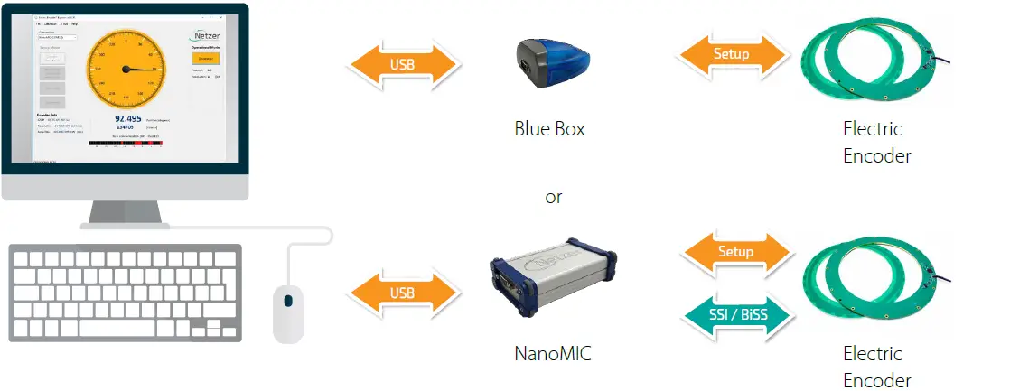
Connect Netzer encoder to the converter, connect the converter to the computer and run the Electric Encoder Explorer Software Tool
Electrical connection and grounding
Observe the following grounding consideration:
- The cable shield electrically floating (unconnected) by default.
- It’s highly recommended to keep the motor PWM wires electrically shielded and/or kept away from the encoder.
Note: 4.75 to 5.25 VDC power supply required
Signal Verification
Starting the Encoder Explorer
Make sure to complete the following tasks successfully:
- Mechanical Mounting
- Electrical Connection to the encoder
- Encoder Explore Software Installation
Run the Encoder Explorer tool (EE)
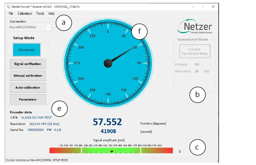
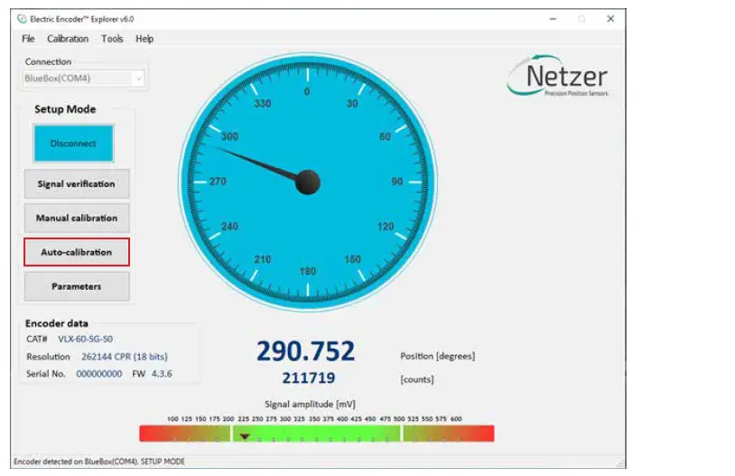
Ensure proper communication with the encoder: (Setup mode by default). The Encoder position-dial is colored blue when in Setup Mode, either through the NanoMic or the BlueBox (a). Note that the operational mode is not available through the BlueBox (b). The Signal amplitude bar indicates whether the signal is within the acceptable tolerance (c) . Note that prior to performing the Signal Verification process the bar could indicate an out of tolerance signal (d). Encoder data is displayed in the encoder data area (CAT No., Serial No.) (e). The position dial display responds to shaft rotation (f).

It is important to perform the Signal Verification process prior to the calibration of the encoder to ensure optimal performance.
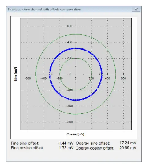
Signal verification process
The Signal Verification process ensures that the encoder is mounted correctly and provides good signal amplitudes. This is performed by collecting raw data of the fine and coarse channels during rotation.
- Select <Signal Verification> on the main screen (a).
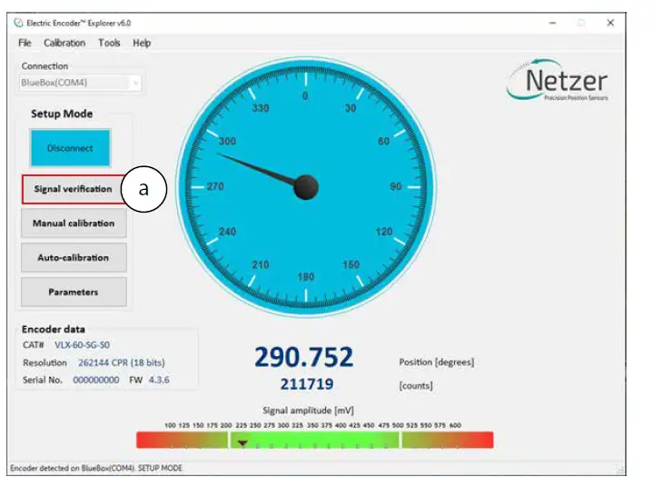
- Select <Start> to initiate the process (b).
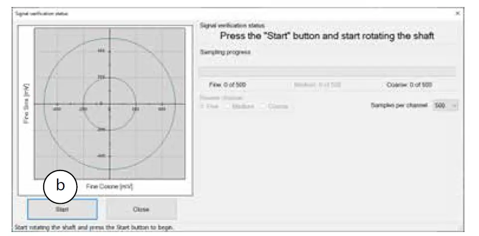
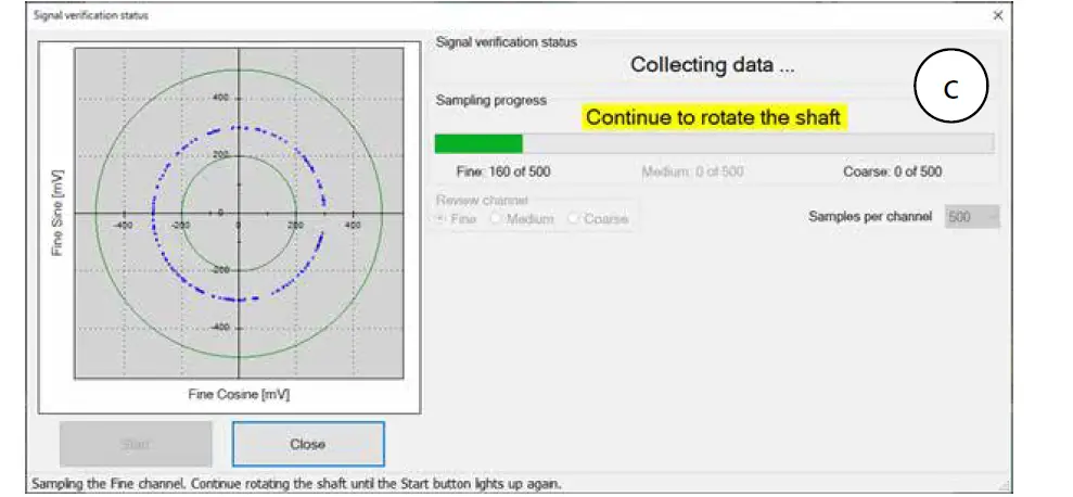
- Rotate the shaft in order to collect the fine and coarse channels data (c).
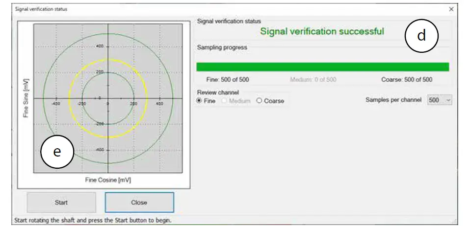
If the process is successful, the status “Signal verification successful” would appear (d). The ‘amplitude circle’ would be centered between the two green circles, preferably in the middle of the tolerance (e).
Note however, that mounting the encoder towards the extreme mechanical tolerances might cause the amplitude circle to be offset from the exact middle of the nominal position. If the signal is out of tolerance the Error notification “Amplitude is lower/higher than the min/max limit of XXX” would appear (g). In Addition, the status “Signal verification failed – perform calibration amplitude” would appear at the top (h).
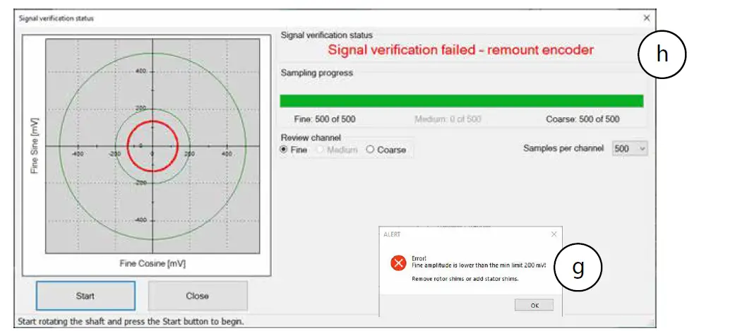
- Stop the process and re-mount the encoder, making sure that the mechanical installation tolerances are not exceeded, removing or adding shims as required.
- Repeat the Signal Verification process after the remount.
Once the signal verification process is successfully completed, proceed to the encoder calibration phase, Section 13
Calibration
It is important that upon every installation of the encoder, the Signal Verification process is completed prior to attempting calibration of the encoder. For encoders with FW 4 version 4.1.3 or higher, it is possible to select either a fully automated calibration process , or a manual phase-by-phase calibration process.
Auto-calibration
Auto Calibration is supported by encoders with FW 4 version 4.1.3 or higher. For these encoders an additional “Auto-calibration” button is displayed.
Auto-calibration process
The Auto-calibration process consists of three stages:
- Jitter test – evaluates the electric noise for the Fine, Medium, and Coarse encoder channels. During the jitter test, the shaft must be stationary.
Attention! The Pass/Fail criteria of the Jitter test is according to very strict factory criteria and failing it would abort the Auto Calibration process.
However, the manual Jitter test as part of the Manual Calibration process in section 13.4, would enable the user to decide whether the jitter is acceptable to its needs. - Offset calibration – performs the offset calibration, the shaft must rotate continuously.
- Absolute Position (AP) calibration – performs Coarse Amplitude Alignment (CAA) and Medium Amplitude Alignment (MAA) are calculated.
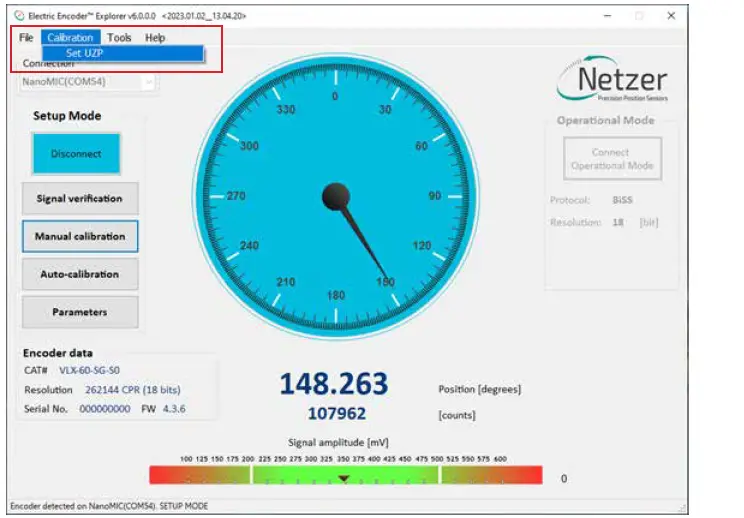
During Auto-Calibration process the encoder’s Zero-Position remain in the factory default zero position for new encoders. It is possible to set the Zero Point through the top menu bar, by selecting “Calibration” tab, and clicking “Set UZP” as defined in section 13.3.
Performing Auto-calibration
Press the <Auto-calibration> button.
The main auto-calibration window opens.
- Select the appropriate measurement range applicable to your application (a).
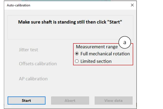
- Make sure to keep the shaft still and press the <Start>
The Noise test would be performed and upon successful completion the “Noise test” label will be marked with a green check mark. The Offset calibration would automatically start upon completion of the Noise test. This calibration requires that the shaft be rotated continuously. The AP calibration would automatically start upon completion of the Accuracy Calibration. Continue rotating the shaft in this phase until the AP calibration is completed, and the encoder is reset. Once the reset is over, the Auto-calibration process is successfully finished.
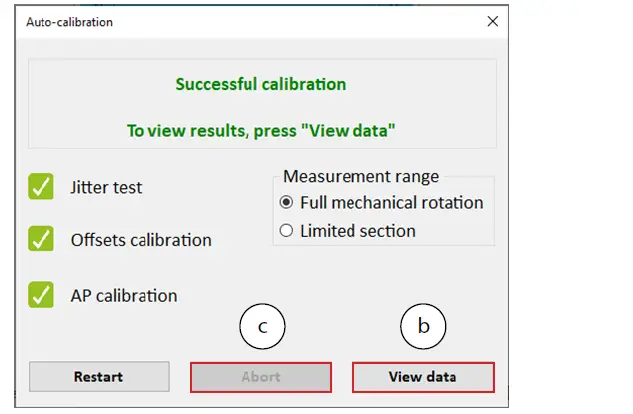
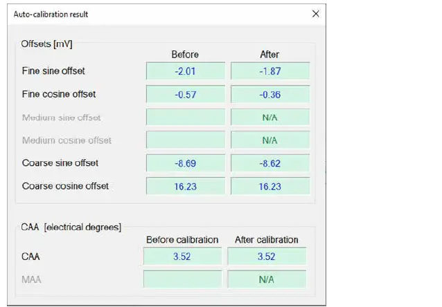
The user can review the calibration results by clicking the <View data> button (b).
It is always possible to abort the Auto Calibration process by clicking the <Abort> button (c).
Auto-calibration failures
If a test fails (for example the Noise test) – the result will be marked with in red X.
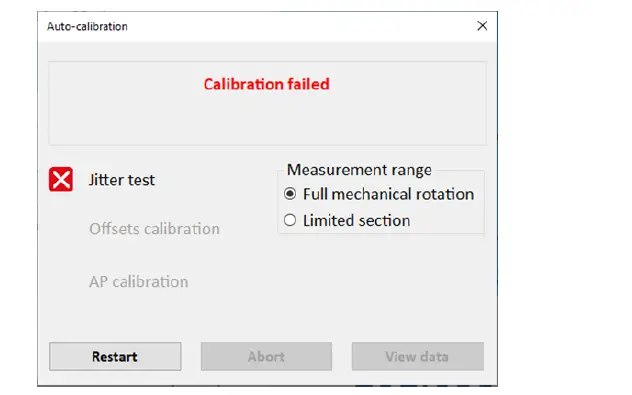
If the calibration process failed, corrective recommendations will be displayed, corresponding to the element which had failed the test.
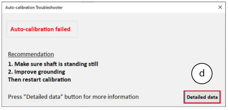
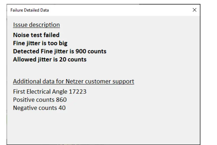
It is possible to review detailed information regarding the failure, by clicking the <Detailed data> button (d).
Setting the zero-position of the encoder
- Select one of the options for setting the zero point and click <Apply and close>.
It is possible to set either current position or rotate the shaft to any other position to be set as the zero point.

It is also possible to set the Zero Point through the top menu bar, by selecting “Calibration” tab, and clicking “Set UZP”.
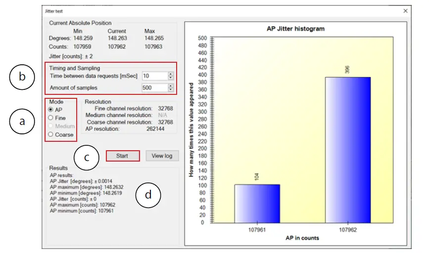
Jitter test
The jitter test is used evaluate the level of electric noise. Common jitter should be up +/- 3 counts; higher jitter may indicate system noise and would require better grounding or shielding of the electric noise source.
- Select “Calibration” tab, and click “Jitter Test”

- Select the Jitter test mode (a).
- Set the Timing and Sampling parameters (b).
- Click <Start> button (c) and check if the results (d) are within acceptable tolerances for the intended application.
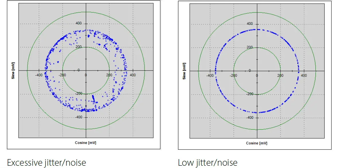
Another indication of excessive jitter/noise when the blue dots in signal amplitude circle are not evenly distributed on a thin circle as appears below.
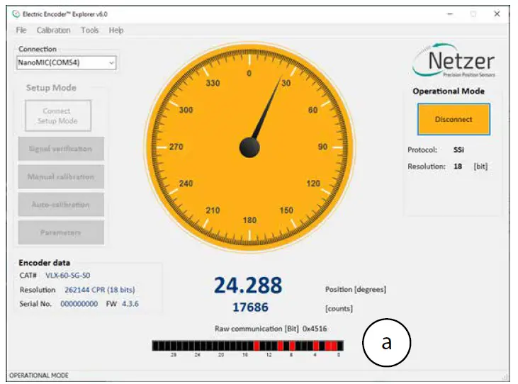
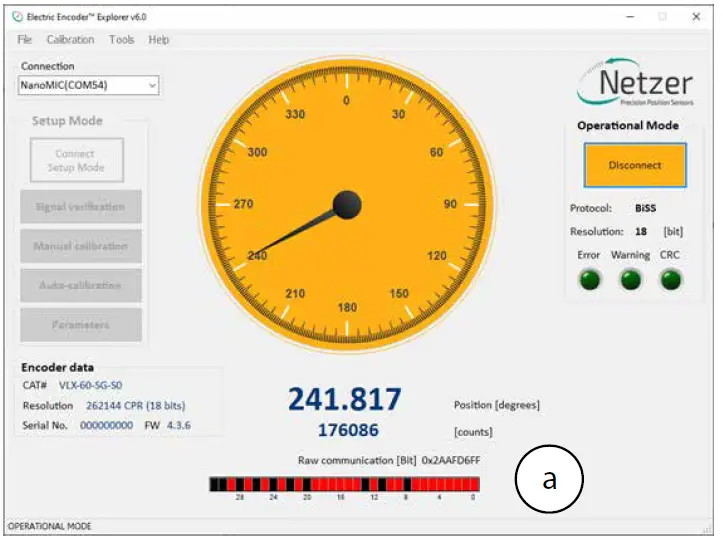
Operational Mode
SSi / BiSS
Operational Mode indication of the SSi / BiSS encoder interface is available by using the NanoMIC to connect with the encoder. When in Operational Mode the color of the position dial is orange.
For more information read about NanoMIC on Netzer website
The operational mode is using SSi / BiSS interface with 1MHz clock rate. The encoder position-dial is colored orange when in Operational Mode. The bar below the dial, is the corresponding binary word output for the current shaft position (a).
SSi Protocol
BiSS Protocol
Corporate Headquarters
ISRAEL
Netzer Precision Position Sensors A.C.S. Ltd.
Misgav Industrial Park, P.O. Box 1359
D.N. Misgav, 2017400
- Tel: +972 4 999 0420
USA
Netzer Precision Position Sensors Inc.
200 Main Street, Salem
NH 03079
- Tel: +1 617 901 0820
- www.netzerprecision.com
Copyright © 2024 Netzer Precision Position Sensors A.C.S. Ltd. All rights reserved.
Documents / Resources
 |
Netzer Precision VLP-247 Hollow Shaft Rotary Encoder Kit Encoder [pdf] User Guide VLP-247, VLP-247, VLP-247 Hollow Shaft Rotary Encoder Kit Encoder, VLP-247, Hollow Shaft Rotary Encoder Kit Encoder, Shaft Rotary Encoder Kit Encoder, Rotary Encoder Kit Encoder, Encoder Kit Encoder, Kit Encoder, Encoder |