netvox R718N37D Wireless Three Phase Current Detection
Wireless Three-phase
Current Detection
R718N3xxxD(E) Series
User Manual
1. Introduction
The R718N3xxxD/DE series is 3-Phase Current Meter device for Netvox Class C type devices based on the LoRaWAN open protocol and is compatible with the LoRaWAN protocol. R718N3xxxD/DE series have different measuring range for different variety of CT.
It is divided into:
| Model | Name | CT cables | ||||||||||||||||||||||||||||||||||||||||||||||||||||||||
| R718N37D | Wireless 3-Phase Current Meter with 3 x 75A Clamp-On CT | – | ||||||||||||||||||||||||||||||||||||||||||||||||||||||||
| R718N37DE | Detachable cables | |||||||||||||||||||||||||||||||||||||||||||||||||||||||||
| R718N315D | Wireless 3-Phase Current Meter with 3 x 150A Clamp-On CT | – | ||||||||||||||||||||||||||||||||||||||||||||||||||||||||
| R718N315DE | Detachable cables | |||||||||||||||||||||||||||||||||||||||||||||||||||||||||
| R718N325D | Wireless 3-Phase Current Meter with 3 x 250A Clamp-On CT | – | ||||||||||||||||||||||||||||||||||||||||||||||||||||||||
| R718N325DE | Detachable cables | |||||||||||||||||||||||||||||||||||||||||||||||||||||||||
| R718N363D | Wireless 3-Phase Current Meter with 3 x 630A Clamp-On CT | – | ||||||||||||||||||||||||||||||||||||||||||||||||||||||||
| R718N363DE | Detachable cables | |||||||||||||||||||||||||||||||||||||||||||||||||||||||||
| R718N3100D | Wireless 3-Phase Current Meter with 3 x 1000A Clamp-On CT | – | ||||||||||||||||||||||||||||||||||||||||||||||||||||||||
| R718N3100DE | Detachable cables | |||||||||||||||||||||||||||||||||||||||||||||||||||||||||
LoRa Wireless Technology:
LoRa is a wireless communication technology famous for its long-distance transmission and low power consumption. Compared with other communication methods, LoRa spread spectrum modulation technique greatly extend the communication distance. It can be widely used in any use case that requires long-distance and low-data wireless communications. For example, automatic meter reading, building automation equipment, wireless security systems, industrial monitoring. It has features like small size, low power consumption, long transmission distance, strong anti-interference ability and so on.
LoRaWAN:
LoRaWAN uses LoRa technology to define end-to-end standard specifications to ensure interoperability between devices and gateways from different manufacturers.
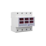
2. Appearance


3. Features
- Adopt SX1276 wireless communication module.
- DC power supply (3.3V/1A)
- Only support AC current measuring
- 3-phase current meter detection
- The base is attached with a magnet that can be attached to a ferromagnetic material object.
- IP30 rating
- LoRaWANTM Class C compatible
- Frequency Hopping Spread Spectrum (FHSS)
- Configuring parameters and reading data via third-party software platforms, and set alarms via SMS text and email (optional)
- Available third-party platform: Actility/ThingPark, TTN, MyDevices/Cayenne
4. Set up Instruction
On/Off
| Power On | Connect the power supply | ||||||||||||||||||||||||||||||||||||||||||||||||||||||||||||||||
| Factory Reset and Restart | Press and hold the function key for 5 seconds until green indicator flashes 20 times. | ||||||||||||||||||||||||||||||||||||||||||||||||||||||||||||||||
| Power Off | Disconnecting the power supply | ||||||||||||||||||||||||||||||||||||||||||||||||||||||||||||||||
| Note | 1. The device will be off in default after disconnecting the power supply. 2. It is suggested to wait for at least 10 seconds between turning the device on and off. 3. At 1st -5th second after power on, the device will be in engineering test mode. |
||||||||||||||||||||||||||||||||||||||||||||||||||||||||||||||||
Network Joining
| Never Joined the Network | Turn on the device, and it will search for the network to join. The green indicator remains on joins the network successfully The green indicator light remains off: fail to join the network |
||||||||||||||||||||||||||||||||||||||||||||||||||||||||||||||||
| Had Joined the Network (Not Back to Factory Setting) |
Turn on the device, and it will search for the previous network to join. The green indicator remains on: joins the network successfully The green indicator light remains off: fail to join the network |
||||||||||||||||||||||||||||||||||||||||||||||||||||||||||||||||
| Fail To Join the Network | Check the device verification information on the gateway or consult your platform server provider. |
||||||||||||||||||||||||||||||||||||||||||||||||||||||||||||||||
Function Key
| Press the Function Key for 5 Seconds | The device will be set to default and restart. The green indicator light flashes 20 times: success The green indicator light remains off: fail |
||||||||||||||||||||||||||||||||||||||||||||||||||||||||||||||||
| Press the Function Key Once | The device is in the network: green indicator light flashes once and sends a report The device is not in the network: green indicator light flashes 3 times |
||||||||||||||||||||||||||||||||||||||||||||||||||||||||||||||||
Sleeping Mode
| The Device is Turned On and In the Network | Sleep period: Min Interval. When the reportchange exceeds setting value or the state changes: send a data report according to Min Interval. |
||||||||||||||||||||||||||||||||||||||||||||||||||||||||||||||||
5. Data Report
The device will immediately send a version packet report along with two uplink packets including 3 current, 3 multiplier and battery voltage.
The device sends data in the default configuration before any configuration is done.
Default Setting:
Max Interval: 0x0384 (900s)
Min Interval: 0x0002 (2s) (Detect per Min Interval)
CurrentChange: 0x0064 (100 mA)
Three-phase Current Detection:
The device would detect and send report of the current value as the function key is triggered or in configuration.
Range and Accuracy:
| CT | Measure1nent Range | Accuracy | |
| R7l 8N37D(E) | Clan1p-011 | 100111A to 75A | ±1% (1neasuren1ent range: 3001nA to 50A) |
| R718N315D(E) | Clan1p-011 | lA to 150A | ±1% |
| R718N325D(E) | Clan1p-on | lA to 250A | ±1% |
| R718N363D(E) | Cla1np-011 | 1OA to 63OA | ±1% |
| R7l 8N3l 00D(E) | Clan1p-011 | 1OA to 1OOOA | ±1% |
Note: Current transformer (measurement range ≤ 75A): report data as 0 when the current < 100mA .
Current transformer (measurement range > 75A): report data as 0 when the current < 1A.
Please refer Netvox LoRaWAN Application Command document and Netvox Lora Command Resolver http://www.netvox.com.cn:8888/cmddoc to resolve uplink data.
Data report configuration and sending period are as follows:
| Min Interval (Unit: second) |
Max Interval (Unit: second) |
Reportable Change | Current Change ≥ Reportable Change |
Current Change< Reportable Change |
||||||||||||||||||||||||||||||||||||||||||||||||||||||||||||
| Any number between 2 to 65535 |
Any number between 2 to 65535 |
Can not be 0 | Report per Min Interval |
Report per Max Interval |
||||||||||||||||||||||||||||||||||||||||||||||||||||||||||||
5.1 Example of ReportDataCmd
FPort:0x06
| Bytes | 1 | 1 | 1 | Var (Fix=8 Bytes) | |||||||||||||||||||||||||||||||||||||||||||||||||||||||||||||
| Version | DeviceType | ReportType | NetvoxPayLoadData | ||||||||||||||||||||||||||||||||||||||||||||||||||||||||||||||
Version– 1 byte –0x01——the Version of NetvoxLoRaWAN Application Command Version
DeviceType– 1 byte – Device Type of Device
The devicetype is listed in Netvox LoRaWAN Application Devicetype .doc
ReportType – 1 byte –the presentation of the NetvoxPayLoadData, according the devicetype
NetvoxPayLoadData– Var (Fix =8bytes)
Tips
1. Battery Voltage:
If the battery is equal to 0x00, it means that the device is powered by a DC power supply.
2. Version Packet:
When Report Type=0x00 is the version packet, such as 014A000A02202405160000, the firmware version is 2024.05.16.
3. Current Value:
The maximum payload of Current is 2 bytes, which means the maximum value that can be shown is 65535mA. To get the actual current value, the current needs to time Multiplier as it exceeds 65535mA.
4. Multiplier:
When ReportTypeSet=0x00 (reporttype1&2), R718N3xxxD(E) will report two data packets, and the multiplier will be either 1 or 10;
When ReportTypeSet=0x01 (reporttype3), R718N3xxxD(E) will report one data packet, and the multiplier will be either 1,5,10 or 100.
(1) When ReportTypeSet=0x00 (reporttype1&2), R718N3xxxD(E) will report two data packets.
| Device | Device Type |
Report Type |
NetvoxPayLoadData | ||||||||||||||||||||||||||||||||||||||||||||||||||||||||||||||
| R718N3xxxD(E) Series |
0x4A | 0x00 | SoftwareVersion (1Byte) Eg.0x0A—V1.0 |
HardwareVersion (1Byte) |
DateCode (4Bytes,eg 0x20170503) |
Reserved (2Bytes,fixed 0x00) |
|||||||||||||||||||||||||||||||||||||||||||||||||||||||||||
| 0x01 | Battery (1Byte,unit:0.1V) |
Current1 (2Bytes,unit:1mA) |
Current2 (2Bytes,unit:1mA) |
Current3 (2Bytes,unit:1mA) |
Mulitplier1 (1Byte) |
||||||||||||||||||||||||||||||||||||||||||||||||||||||||||||
| 0x02 | Battery (1Byte, unit:0.1V) |
Mulitplier2 (1Byte) |
Mulitplier3 (1Byte) |
Reserved (5Bytes,fixed 0x00) |
|||||||||||||||||||||||||||||||||||||||||||||||||||||||||||||
Uplink:
# Packet 1: 014A010005DD05D41B5801
# Packet 2 : 014A0200010A0000000000

(2) When ReportTypeSet=0x01 (reporttype3), R718N3xxxD(E) will report one data packet.


5.2 Example of Threshold Alarm

Uplink:
014A040001000000000000
1st byte (01): Version
2nd byte (4A): DeviceType- R718N3xxxD(E) Series
3rd byte (04): ReportType
4th byte (00): Battery-DC power
5th byte (01): ThresholdAlarm – bit 0=1 LowCurrent1Alarm
// 0x01 = 00000001 (Bin)
6th-11th byte (000000000000): Reserved
5.3 Example of ConfigureCmd

(1) Configure device parameters MinTime = 60s (0x003C), MaxTime = 60s (0x003C), CurrentChange = 100mA (0x0064)
Downlink: 014A003C003C0064000000
The device returns:
814A000000000000000000 (Configuration successful)
814A010000000000000000 (Configuration failed)
(2) Read Configuration
Downlink: 024A000000000000000000
The device returns:
824A003C003C0064000000 (Current device configuration parameters)
5.4 Example of SetRportType
FPort:0x07
Set the R718N3xxxD(E) data to send either one or two packets.

(1)Configure ReportTypeSet =0x01
Downlink: 014A010000000000000000 // 0x01 Uplink return one packet.
The device returns:
834A000000000000000000 (Configuration successful)
834A010000000000000000 (Configuration failed)
(2)Read device configuration parameters.
Downlink: 044A000000000000000000
The device returns:
844A010000000000000000 (Current device configuration parameters)
5.5 Example of SetSensorAlarmThresholdCmd

(1) SetSensorAlarmThresholdReq
Set Current1 HighThresholdt to 500mA, LowThreshold to100mA
Downlink: 010027000001F400000064 //1F4 (Hex) = 500 (Dec), 500* 1mA = 500mA;
64 (Hex) = 100 (Dec), 64* 1mA = 64mA
Response: 8100000000000000000000
(2) GetSensorAlarmThresholdReq
Downlink: 0200270000000000000000
Response: 820027000001F400000064
(3) Disable all sensor thresholds for channel 1.
Configure the Sensor Type to 0
Downlink: 0100000000000000000000
Response: 8100000000000000000000
5.6 Example of NetvoxLoRaWANRejoin
Check if the device is still in the network. If the device is disconnected, it will automatically rejoin back to the network.

(1) Command Configuration
Set RejoinCheckPeriod = 3600s (0x00000E10), RejoinThreshold = 3 times
Downlink: 0100000E1003
Response:
810000000000 (Configuration success)
810100000000 (Configuration failure)
(2) Read current configuration
RejoinCheckPeriod, RejoinThreshold
Downlink: 020000000000
Rthe esponse: 8200000E1003
6. Installation
1. The 3-phase current meter R718N3xxxD(E) has a built-in
magnet (see Figure 1 below). It can be attached to the surface of an object with iron during installation, which is convenient and quick.
To make the installation more secure, please use screws (purchased separately) to fix the device to the wall or other objects (such as the installation diagram).
Note:
Do not install the device in a metal shielded box or in an environment surrounded by other electrical equipment to avoid affecting the wireless transmission of the device.

2. Open the clamp-on current transformer, and then pass the live wire through the current transformer according to the installation.
Note: “L←K” is marked on the bottom of the CT.
3. Precautions:
- Before using, user must check whether the appearance is deformed; otherwise, the test accuracy will be affected.
- The using environment should be kept away from strong magnetic fields, so as not to affect the test accuracy. It is strictly forbidden to use in humid and corrosive gas environments.
- Before installation, please confirm the current value of the load. If the current value of the load is higher than the measurement range, select a model with a higher measurement range.
4. The 3-phase current meter R718N3xxxD(E) samples the current according to MinTime. If the current value sampled this time relatively exceeds the set value (the default is 100mA) more than the current value reported last time, the device will immediately report the current value sampled this time. If the current variation does not exceed the default value, the data will be reported regularly according to MaxTime.
5. Press the function key of the device to start sampling data and report the data after 3 to 5 seconds.
Note: MaxTime must be set greater than Min Time.
The three-phase current detector R718N3xxxD(E) is suitable for the following scenarios:
- School
- Factory
- Shopping mall
- Office building
- Smart building
Where the electrical data of the device with the three-phase electricity needs to be detected.

Installation Diagram

7. Important Maintenance Instruction
Kindly pay attention to the following in order to achieve the best maintenance of the product:
- Keep the device dry. Rain, moisture, or any liquid might contain minerals and thus corrode electronic circuits. If the device gets wet, please dry it completely.
- Do not use or store the device in dusty or dirty environment. It might damage its detachable parts and electronic components.
- Do not store the device under excessive hot condition. High temperature can shorten the life of electronic devices, destroy batteries, and deform or melt some plastic parts.
- Do not store the device in places that are too cold. Otherwise, when the temperature rises to normal temperature, moisture will form inside, which will destroy the board.
- Do not throw, knock or shake the device. Rough handling of device can destroy internal circuit boards and delicate structures.
- Do not clean the device with strong chemicals, detergents or strong detergents.
- Do not apply the device with paint. Smudges might block in the device and affect the operation.
All of the above applies to your device, battery and accessories.
If any device is not working properly, please take it to the nearest authorized service facility for repair.
Specifications
- Product: R718N3xxxD/DE Series – Wireless Three-Phase Current Detection
- Models: R718N37D, R718N37DE, R718N315D,
R718N315DE, R718N325D, R718N325DE, R718N363D, R718N363DE,
R718N3100D, R718N3100DE - Features: Different measuring ranges for various CT types
- Wireless Technology: LoRa with long-distance transmission and low power consumption
FAQ
Q: What are the different models available in the R718N3xxxD/DE series?
A: The available models are R718N37D, R718N37DE, R718N315D, R718N315DE, R718N325D, R718N325DE, R718N363D, R718N363DE, R718N3100D, R718N3100DE.
Q: What is the wireless technology used in this product?
A: The product uses LoRa wireless technology known for its long-distance transmission capabilities and low power consumption.
Documents / Resources
 |
netvox R718N37D Wireless Three Phase Current Detection [pdf] User Manual R718N37D, R718N37DE, R718N315D, R718N315DE, R718N325D, R718N325DE, R718N363D, R718N363DE, R718N3100D, R718N3100DE, R718N37D Wireless Three Phase Current Detection, R718N37D, Wireless Three Phase Current Detection, Three Phase Current Detection, Phase Current Detection, Current Detection, Detection |