![]() Operating instructions for
Operating instructions for
Sequence Control Systems
Type NASmini 8
DC 24 V 87414700 Flow Controller

These operating instructions apply to:
NASmini 8 AC 230 V
NASmini 8 DC 24 V
NASmini 8 AC 230 V

NASmini 8 DC 24 V

| Scope of delivery | Please refer to the delivery note for the scope of delivery. Check the packaging for possible transport damage. In the event of damage to the packaging, check the contents for completeness and possible damage. Inform the carrier in the case of damage. |
| Designation | The Sequence Control Systems NASmini 8 are hereafter referred to as “NAS”. |
Version of document
| Document no. | 2171E |
| Version no. | 1 |
| Date of issue | February 2024 |
General information
Use and storage
Before installing the NAS read these instructions carefully. It is the basis for any action when dealing with the NAS, and may be used for training purposes. The instructions should be subsequently stored at the operation site.
Target group
The target group for these instructions is technical staff, who have basic knowledge in electrics and mechanics.
Only complying technical staff may work on the NAS.
The NAS may only be installed, put into operation, maintained, troubleshot and disassembled by persons authorised by the operator.
Copyright
This documentation is protected by copyright.
NetterVibration reserves all rights such as translations, reprinting and reproduction of the instructions, as well as parts thereof.
Limitation of liability
All technical information, data and instructions for installation, operation and maintenance in these instructions are based on the latest information available at the time of printing and take our past experience to the best of our knowledge into account.
No claims can be derived from the information, illustrations and descriptions in these operating instructions.
The manufacturer does not assume liability for damages resulting from:
- failure to observe the instructions,
- improper use,
- unauthorised repairs,
- technical modifications,
- use of non-permissible spare parts.
Translations are made to the best of our knowledge.
NetterVibration does not assume liability for translation errors, even if the translation was made by us or on our behalf. Only the original German text remains binding.
Directives / standards observed
The Sequence Control Systems NASmini 8 are build according to the following directives:
- 2014/35/EU – low voltage directive
- S.I. 2016:1101 – Electrical Equipment (Safety) Regulations 2016 (UK)
- 2014/30/EU – electromagnetic compatibility directive
- S.I. 2016:1091 – Electromagnetic Compatibility Regulations 2016 (UK)
The main standards observed are indicated in the CE declaration of conformity.
The rules and regulations of the local associations for electrical engineering apply (e. g. IEC, VDE, OEVE, SEV, etc.).
Instruction and warning symbols
The following instruction and warning symbols are used in these instructions:
Personal injuries
![]() DANGER
DANGER
![]() indicates an immediate danger.
indicates an immediate danger.
Disregard of this notice will result in death or severe personal injuries.
![]() WARNING
WARNING
![]() indicates a potential danger.
indicates a potential danger.
Disregard of this notice can result in death or severe personal injuries.
![]() CAUTION
CAUTION
![]() indicates a potentially dangerous situation.
indicates a potentially dangerous situation.
Disregard of this notice can result in minor or moderate personal injuries.
Material damages
NOTICE
indicates potential material damage.
Disregard of this notice can result in material damage.
Notes
IMPORTANT
indicates actions, methods or notes that are not relative to safety, e.g. useful information and tips.
![]() Environmentally safe disposal
Environmentally safe disposal
indicates the obligation of environmentally safe disposal.
Safety
Intended use
The NAS are controllers intended for the clocked actuation of vibrators.
The NAS enable the switching on and off of electric vibrators, pneumatic vibrators, pneumatic impactors and other drives with second precision.
They are controlled via solenoid valves or power contactors.
Any other use is considered improper.
Qualification of qualified personnel
Installation, commissioning, maintenance and troubleshooting of the NAS may only be performed by authorised qualified personnel, who have basic knowledge in electrics and mechanics.
All handling of the NAS is the responsibility of the operator.
High voltage
![]() DANGER
DANGER
Risk of electric shock due to high voltage
Live parts can cause severe injuries or even death.
![]() Installation, connection, commissioning, maintenance and disassembly of the NAS may only be carried out by authorized qualified personnel.
Installation, connection, commissioning, maintenance and disassembly of the NAS may only be carried out by authorized qualified personnel.
![]() The housing of the NAS must not be opened when live.
The housing of the NAS must not be opened when live.
![]() Installation, connection, maintenance and disassembly may only be carried out in a voltage-free state.
Installation, connection, maintenance and disassembly may only be carried out in a voltage-free state.
![]() When handling the NAS the provisions and regulations of the local electrical engineering associations (e.g. VDE) and the accident prevention regulations must be observed.
When handling the NAS the provisions and regulations of the local electrical engineering associations (e.g. VDE) and the accident prevention regulations must be observed.
![]() Perform all work only with insulated tools suitable for the application.
Perform all work only with insulated tools suitable for the application.
Safety rules
![]() DANGER
DANGER
Electric shock
An electric shock will result in serious injury or even death. The NAS must be free of voltage during assembly, start-up, maintenance and troubleshooting.
Observe the following five safety rules:
- Disconnect the NAS from the mains supply.
- Secure the NAS against re-activation.
- Establish that the NAS has no voltage.
- Earth and short-circuit the power supply of the NAS.
- Cover adjacent live parts or fence them off.
Electric shock
![]() DANGER
DANGER
![]() Danger of electric shock due to incorrect or wrongly laid electrical cables
Danger of electric shock due to incorrect or wrongly laid electrical cables
Incorrect or improperly laid electrical wiring can cause electric shock and result in serious injury or even death.
![]() Lay electrical cables carefully. Make sure that electrical cables are not worn through vibrating parts or sharp edges.
Lay electrical cables carefully. Make sure that electrical cables are not worn through vibrating parts or sharp edges.
![]() Protect the electrical lines from high temperatures and lubricants.
Protect the electrical lines from high temperatures and lubricants.
![]() Only use suitable, flexible feed cables to connect the NAS. The conductors in the supply cable must be temperature-resistant and have a sufficiently large crosssection matched to the cable length.
Only use suitable, flexible feed cables to connect the NAS. The conductors in the supply cable must be temperature-resistant and have a sufficiently large crosssection matched to the cable length.
![]() Check the perfect condition of the electric cables and plugs regularly. Detected errors must be eliminated immediately.
Check the perfect condition of the electric cables and plugs regularly. Detected errors must be eliminated immediately.
Automatic start-up
![]() WARNING
WARNING
Risk of injury due to automatic start-up
If the mains connection is supplied with voltage again after a voltage interruption, the next cycle always starts with the set working time. The output of the NAS is immediately energized. Automatically starting vibrators and drives can lead to serious personal injury.
![]() Check that the vibrators or drives can start up without danger before applying voltage to the mains connection.
Check that the vibrators or drives can start up without danger before applying voltage to the mains connection.
Technical data
Operating conditions and technical data
NASmini 8 AC
| Parameter | Values |
| Supply voltage | 100 V to 240 V AC, 50 Hz to 60 Hz |
| Switching voltage | 24 V DC |
NASmini 8 DC
| Parameter | Values |
| Supply voltage | 24 V DC ± 10% |
| Switching voltage | 24 V DC |
NASmini 8 AC und DC
| Parameter | Values |
| Power consumption | 30 VA, self-consumption approx. 3 W |
| Switching current | max. 1 A with a duty time ≤ 1 s and a pause time ≥ the duty time The connections are short-circuit-proof. |
| Output power | min. 0,5 W / max. 24 W |
| Fuse | Glass fuse, 2A slow-blow |
| Valve outlets | 1 to 8 |
| Connections | 1 x cable gland M25 x 1,5, metric 2 x cable gland M32 x 1,5, metric Multiple sealing inserts and locking bolts |
| Working time (PULSE) | from 0,5 s to 30 s |
| Pause time (PAUSE) | from 2 s to 540 s |
| Permissible ambient temperature | -20°C to +50°C |
| Protection class | IP 65 Protection class IP 65 can only be achieved if the supplied cable glands and sealing inserts are installed correctly and the correct cable crosssections are used. |
The technical data of your NAS can be found on the type plate.
Technical data
Type plate

Dimensions

Design and function
Design
NASmini 8 DC

| No. | Element | Function |
| 1 | Housing | Contains and protects the internal components. |
| 2 | Glass fuse (only for 24 V DC version) | Securing the NAS in the event of a fault. |
| 3 | terminal block | Connecting the NAS electrically. Detailed description in separate section. |
| 4 | Mounting holes (Ø 4,5 mm) | Mount NAS. |
| 5 | Cable glands | Feed connection cable. |
| 6 | Button: TEST and LED (green) | testing the function of the NAS. |
| 7 | Potentiometer: PAUSE and LED (yellow) | Set and display pause time. |
| 8 | Potentiometer: PULSE and LED (yellow) | Set and display duty time (pulse time). |
| 9 | Coding switch: Cycles | Set the number of cycles. |
| 10 | Operating light: LED (green) | Lights up when NAS is ready for operation. |
NASmini 8 AC
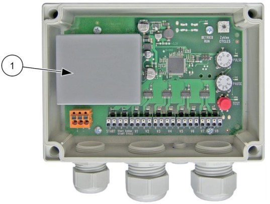
| No. | Element | Function |
| 1 | Power supply unit | Voltage transformer and fuse protection. |
Connector block

| No. | Connection | Description |
| 1 | L (+) | Supply voltage L, 100-240 V AC or (+) 24 V DC |
| 2 | N (-) | Supply voltage N, 100-240 V AC or (-) 24 V DC. |
| 3 | PE | Potential earth. |
| 4 | + START | Input START (+), active low, potential-free. |
| 5 | – START | Input START (-), potential-free. |
| 6 | + Start cycle | Input cycles (+), active low, potential-free. |
| 7 | – Start cycle | Input cycles (-), potential-free. |
| 8 | + V1 to + V8 – V1 to + V8 |
Output 1-8 (+24V DC) Output 1-8 (GND) |
Design and function
Function
The NAS are suitable for the cycled actuation of up to 8 pneumatic or elec-tric vibrators. The sequence begins with the duty time (PULSE), which can be set to between 0.5 s and 30 s. During this time, 24V DC is applied to the connected output.
When the duty time elapses, the pause time (PAUSE) runs for 2 s to 540 s. This cycle then moves to the next output. Once all connected outputs have been processed once (duty time and pause time), the sequence starts again at the first connected output.
Transport and storage
Transport conditions
Special conditions of transport are not required.
Packaging
The NAS are packed ready for installation.
The packaging protects the NAS from transport damage. The packaging material has been selected from an environmentally safe and technically disposable point of view and is therefore recyclable.
The return of packaging to the material cycle conserves raw materials and reduces the amount of waste.
Storage
- Store the NAS in a dry and clean environment.
- The permissible storage temperature is between -20 °C and +50 °C.
- The permissible relative humidity is max. 60 %.
- Do not store the NAS outdoors. The electrical components are not protected against corrosion.
Installation
![]() Mount and connect NAS
Mount and connect NAS
Observe the safety instructions in chap. Safety, starting on page 5.
- Unscrew the four crosshead screws from the cover.
- Remove the cover.
- Screw the NAS onto a clean and flat mounting surface (± 0.1 mm flat- ness) using suitable screws via the mounting holes.
The NAS can be mounted in any position. - Connect the NAS via the terminals on the connector block, see chapter “Design”, section “Connector block”.
Inputs
The solenoid valve control has 2 inputs: START and START CYCLE. The inputs are supplied with + 24 V DC internally and can be switched to (-) with a potential-free contact.
Outputs (valves)
| Connection | Terminals V1 to V8 (+ and -) |
| Valve type | 24 V DC, max. 1 A, min. 0,5 W |
| Shared potential | – |
| Switched output | + |
The outputs are short-circuit proof.
Commands
| Continuous operation | Connect terminals START (+ and -). |
| Cycle operation | Connect terminals START CYCLE (+ and -) (trigger signal). |
Start-up and operation
![]() Observe the safety instructions in chap. Safety, starting on page 5.
Observe the safety instructions in chap. Safety, starting on page 5.
Permissible operating conditions
Please refer to chap. Technical data, page 7 for permissible operating conditions.
Regulations
Installation work as well as operation of the system are to be carried out taking the valid accident prevention regulations into account.
The operator is responsible for the proper condition of the system.
Measures
Carry out the following measures before start-up:
- Check the mains voltage and the grid feed-in.
- Check that the system is in perfect electrical condition.
- Check that all protective measures on the system have been observed.
- Check that the cables are undamaged and laid according to the known regulations and standards.
- Eliminate possible errors.
Adjusting the duty time
WARNING:
When switched on the NAS starts immediately with the stored time values.
The connected vibrators start immediately. The output is immediately energized.
| Coding switch Cycles |  |
Set the number of cycles from 1 to 9. The set number of cycles is processed, after which the cycle control stops; the “Cycle” function is deactivated in position 0. |
| LED operation (green) | Lights up when operating voltage is applied and processor is active. | |
| Potentiometer PULSE |  |
Set the duty time from 0.5 s to 30 s using the PULSE potentiometer. |
| LED PULSE (yellow) | The LED lights up during the actuation time (pulse). | |
| Potentiometer PAUSE |  |
Set the pause time from 2 s to 540 s using the PAUSE potentiometer. |
| LED PAUSE (yellow) | The LED lights up during the pause until the next valve is actuated. | |
| Button TEST |  |
Pressing the button once starts a pulse and a pause at the next output. Pressing the button again interrupts the pause of the active output or starts the next output. If you press the button for longer than 2 seconds, the set number of cycles is processed. If the coding switch cycles is set to zero, continuous operation is carried out as long as the button is pressed. |
| LED TEST (green) | The LED lights up for the entire duration of a test. | |
| Outputs V1 to V8 with status LEDs |
The connected devices are automatically recognized by the control unit. Detected devices are indicated by a glowing LED (red). When the output is switched, the LED lights up. The control unit only ever processes the connected outputs with the set working and pause time. Unused outputs are skipped in the cycle. | |
| Input Cycle start (trigger signal) |
The set cycle starts with a trigger signal at the cycle terminal (+ and -). | |
| Input START (Continuous signal) |
Continuous operation is carried out as long as a signal is present at the START terminal. |
Start-up and operation
Connection example

Sequence diagram for the connection example (continuous operation):
| Input: | START (continuous operation) |
| PULSE (pulse time) | 1 s |
| PAUSE (pause time) | 2 s |

Sequence diagram for the connection example (cycle operation):
| Input: | Start cycle |
| Number of cycles | 2 |
| PULSE (pulse time) | 1 s |
| PAUSE (pause time) | 2 s |

Maintenance and servicing
![]() Observe the safety instructions in chap. Safety, starting on page 5.
Observe the safety instructions in chap. Safety, starting on page 5.
Maintenance plan
Maintenance of the NAS must be carried out as follows:
| Interval | Action |
| If required | Remove dust deposits from the housing of the NAS with a lint-free cloth. |
| Every 6 month | Check proper condition of connecting cables and plugs. When the NAS is exposed to constant weather influences: Check the seal in the cover and the electrical cables for porosity. Replace porous seal and leads. |
| At least every 4 years | Check proper condition of electrical systems and stationary electrical equipment. |
Troubleshooting
![]() Observe the safety instructions in chap. Safety, starting on page 5.
Observe the safety instructions in chap. Safety, starting on page 5.
Expertise and regulations
Electrical faults may only be processed by a qualified electrician. Work on the NAS may only be carried out by authorised persons.
In the case of unauthorised intervention in the NAS there is no longer any warranty claim. Interventions of any kind are to be agreed upon with NetterVibration.
Malfunctions and causes
In the case of malfunctions of the NAS proceed as follows:
| Malfunction | Possible causes | Corrective action |
| NAS does not start | Phase interruption | Check fuse (for 24 V version) and connection cables and replace if necessary. |
| Mains voltage too low | Adjust mains voltage. Check cables and replace if necessary. |
|
| Cable cores are connected with reversed polarity | Connect cable cores in correct polarity. |
Disposal
Disposal
![]() All parts of the NAS must be disposed of properly according to the material specifications. Do not dispose the electrical and electronic components of the NAS in the normal household waste, but in a special collection point for the environmentally friendly disposal of electrical equipment. Observe the national regulations for disposal.
All parts of the NAS must be disposed of properly according to the material specifications. Do not dispose the electrical and electronic components of the NAS in the normal household waste, but in a special collection point for the environmentally friendly disposal of electrical equipment. Observe the national regulations for disposal.
The NAS consist of electronic parts and components and a polycarbonate housing.
Annex
The declaration of conformity can be found at: www.NetterVibration.com
![]() February 2024
February 2024
No. 2171E
Netter GmbH
Fritz-Lenges-Str. 3
55252 Mainz-Kastel
Germany, Switzerland, Poland, Spain
Australia, United Kingdom, France
www.NetterVibration.com
Documents / Resources
 |
NetterVibration DC 24 V 87414700 Flow Controller [pdf] User Guide DC 24 V 87414700 Flow Controller, DC 24 V 87414700, Flow Controller, Controller |