NAXOM OP-O4-1a Communication Module
Installation of the water meter clip-on module
Compatibility with water meters:
- NAXOM-1 (OP-O4-1a)* – only for selected radio profile and selected JS/JS90 1.6÷2.5 Smart+; JS 1.6÷2.5 Smart C+; JS/JS90 1.6÷2.5 Smart D+ water meters.
- NAXOM-1 (OP-O4-1b) – for all available radio profiles and JS/JS90 1.6÷4 Smart +; JS 1.6÷4 Smart C+; JS/JS90 1.6÷4 Smart D+ water meters.
- NAXOM-2 (OP-O4-2) – for all available radio profiles and SV-RTK2.5÷4, SV-RTK16 series water meters.
Does not apply to the water main profile.
Installation of the NAXOM-1 module, OP-O4-1a
The first step in installing the OP-4-1a module is to locate the centring protrusion on the housing. It has been indicated in the drawing below.
The centring protrusion should be positioned so that when placing the module on the water meter glass, it is inside the recess located on the water meter glass at number 1.
After correctly applying the module on the water meter glass, gently press it against the meter glass so that the module latches snap into place on the meter glass.

Installation of the NAXOM-1 module, OP-O4-1b
The first step in installing the OP-4-1b module is to locate the centring protrusion on the housing. It has been indicated in the drawing below.

The centring protrusion should be positioned so that when placing the module on the water meter glass, it is inside the recess located on the water meter glass at number 1.

After correctly applying the module on the water meter glass, gently press it against the meter glass so that the module latches snap into place on the meter glass.
Installation of the NAXOM-2 module, OP-O4-2
The first step in installing the OP-4-2 module is to locate the centring protrusion on the housing. It has been indicated in the drawing below.

The centring protrusion should be positioned so that when placing the module on the water meter glass, it is inside the recess located on the water meter glass.

After correctly applying the module on the water meter glass, gently press it against the meter glass so that the module latches snap into place on the meter glass.

Configuration of the module in the SPIDAP Mobile application using the Installation and Service panel – “Wmbus – installment”
The radio module produced by Apator Powogaz S.A. can be delivered to the customer in two ways:
- The module arrives at the customer’s location installed on the water meter, fully configured and with the appropriate profile uploaded, depending on the type of water meter it is installed on. Such a module is ready for operation but remains in sleep mode. The customer must wake it up using a magnet. The factory configuration is confirmed by a warranty sticker placed at the connection between the radio module and the water meters.
- Only the module itself is delivered to the customer. The module must undergo the installation and configuration process on the operational water meter at the customer’s location.
Waking up the module using a magnet
To wake up the sleeping module, a neodymium magnet with a diameter of 10 mm and a thickness of 3 mm or a ferrite magnet with a diameter of 20 mm and a thickness of 5 mm should be placed for at least 10 seconds. The magnet should be placed on the module housing above the optical system at the location indicated in the photo below.

Installation and configuration of the module on the operational water meter
Before starting to use the mobile application, Bluetooth must be enabled on the phone to connect to the APT-VERTI-1 converter located nearby. Then log in to the SPIDAP Mobile application (Fig. 11). After logging in, select settings in the upper left corner (Fig. 12) and go to Bluetooth devices (Fig. 13). Once the converter is turned on, select it from the device list (it can be recognized by the device’s serial number, which is located on the label at the back of the converter), as shown in Fig. 14.


After selecting the VERTI converter, the “Bluetooth pairing request” window will appear (Fig. 15). The password for the converter is: 0000. After confirmation, the device will be paired.
Next, go to the “Installation and Service” tab with the APT-VERTI-1 converter enabled and select the “Wmbus – installment” field.

After selecting the “Wmbus – installment” tab, a window for module configuration will appear. Select the appropriate device type to be installed on the water meter, choose the profile corresponding to the module and the size of the water meter, and then fill in: the radio number of the module, the serial number of the water meter, and the water meter reading. Then enter the access code, which is the AES key (a description of where to find the key is in point 2.3.). Leave the “Action” field unchanged – it is by default selected as “Record”. After completing all the data, confirm the installation of the module by selecting the “Execute” option. 
Required fields to fill in
- Radio number
- Water meter number
- Meter reading
- Access code (AES key)
During programming, the VERTI converter must remain powered on at all times!

The image shows the OP-04-1a module with the radio number highlighted, along with the information required for configuring the module in SPIDAP Mobile using the example of the JS1.6-03 water meter. Similar information layout applies to SV-RTK2.5÷4 and SV-RTK16 water meters.

AES keys (access codes)
Data sent by the modules OP-O4-1a, OP-O4-1b, and OP-O4-2 are originally secured with individual access codes, known as AES keys. After purchasing the modules, their serial numbers and AES keys are automatically assigned to the customer’s account in SPIDAP Engine, allowing the customer to securely retrieve them from their account. This is the safest way to distribute sensitive data.
Other information
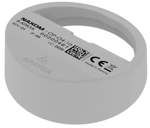
Information contained on the module housing

Information transmitted in the radio frame
- Volume
- Water meter number
- Clock, date
- Event flags
- Event details
- Volume history
- Current flow
Module profiles
Tabela 1. Profiles for NAXOM modules.

Symbols:
- ST – Stationary System
- SM – Housing Co-operative
- WOD – Water Main
Temperature-dependent:
Module operation in the following temperature ranges: 80% of operating time at 30°C maximum; 10% of operating time at 30–40°C; 10% of operating time at 55°C maximum. The applied temperature profile matches the average temperature profile for the housing sector.
Apator Powogaz S.A.
- ADDRESS: ul. Klemensa Janickiego 23/25, 60-542 Poznań
- tel. +48 (61) 84 18 101
- fax +48 (61) 84 70 192
- e-mail sekretariat.powogaz@apator.com
- www.apator.com
Documents / Resources
 |
NAXOM OP-O4-1a Communication Module [pdf] Installation Guide NAXOM-1, OP-O4-1a, OP-O4-1b, OP-O4-2, OP-O4-1a Communication Module, OP-O4-1a, Communication Module, Module |