![]()
 User Manual
Murata Manufacturing Co.,Ltd.
LBEE5WV2GF Wi-Fi Bluetooth Module
- Regarding FCC modular approval of LBEE5WV2GF
Model Name: LBEE5WV2GF
FCC ID:VPYLBEE5WV2GF
Since this module is not sold to general end users directly, there is no user manual of module.
For the details about this module, please refer to the specification sheet of module.
This module should be installed in the host device according to the interface specification (installation procedure)
The OEM integrator has to be aware not to provide information to the end user regarding how to install or remove this RF module in the end user’s manual of the end product which integrates this module.
The end user manual shall include all required regulatory information/warning as shown in User manual.
This device complies with part 15 of the FCC Rules. Operation is subject to the following two conditions: (1) This device may not cause harmful interference, and (2) this device must accept any interference received, including interference that may cause undesired operation.
Since this module is not sold to general end users directly, there is no user manual of module.
For the details about this module, please refer to the specification sheet of module.
This module should be installed in the host device according to the interface specification (installation procedure).
- The following information must be indicated on the host device of this module.
Contains Transmitter Module FCC ID: VPYLBEE5WV2GF or Contains FCC ID: VPYLBEE5WV2GF
This device complies with part 15 of the FCC Rules. Operation is subject to the following two conditions: (1) This device may not cause harmful interference, and (2) this device must accept any interference received, including interference that may cause undesired operation.
*If it can not be described on the host product, it must be listed on both the host product manual and on the host product package or removable label.
- The following statements must be described on the user manual of the host device of this module;
FCC CAUTION
Changes or modifications not expressly approved by the party responsible for compliance could void the user’s authority to operate the equipment.
Compliance with FCC requirement 15.407(c)
Data transmission is always initiated by software, which is the passed down through the MAC, through the digital and analog baseband, and finally to the RF chip. Several special packets are initiated by the MAC. These are the only ways the digital baseband portion will turn on the RF transmitter, which it then turns off at the end of the packet. Therefore, the transmitter will be on only while one of the aforementioned packets is being transmitted. In other words, this device automatically discontinue transmission in case of either absence of information to transmit or operational failure.
Frequency Tolerance: ±20 ppm
This transmitter must not be co-located or operated in conjunction with any other antenna or transmitter.
- When installing it in a mobile equipment.
Please describe the following warning to the manual.
This equipment complies with FCC radiation exposure limits set forth for an uncontrolled environment and meets the FCC radio frequency (RF) Exposure Guidelines. This equipment should be installed and operated keeping the radiator at least 20cm or more away from person’s body. - When installing it in a portable equipment.
Please describe the following warning to the manual.
The available scientific evidence does not show that any health problems are associated with using low power wireless devices. There is no proof, however, that these low power wireless devices are absolutely safe. Low power Wireless devices emit low levels of radio frequency energy (RF) in the microwave range while being used. Whereas high levels of RF can produce health effects (by heating tissue), exposure of low-level RF that does not produce heating effects causes no known adverse health effects. Many studies of low-level RF exposures have not found any biological effects. Some studies have suggested that some biological effects might occur, but such findings have not been confirmed by additional research. LBEE5HY1MW has been tested and found to comply with FCC radiation exposure limits set forth for an uncontrolled environment and meets the FCC radio frequency (RF) Exposure Guidelines.
It is necessary to take a SAR test with your set mounting this module.
Class II permissive change application is necessary using the SAR report. Please contact Murata.
Note
Portable equipment : Equipment for which the spaces between human body and antenna are used within 20cm.
Mobile equipment : Equipment used at position in which the spaces between human body and antenna exceeded 20cm.
- If the final product with this module is FCC Class A digital device, include the following in the manual of the final product:
Note: This equipment has been tested and found to comply with the limits for a Class A digital device, pursuant to part 15 of the FCC Rules. These limits are designed to provide reasonable protection against harmful interference when the equipment is operated in a commercial environment. This equipment generates, uses, and can radiate radio frequency energy and, if not installed and used in accordance with the instruction manual, may cause harmful interference to radio communications. Operation of this equipment in a residential area is likely to cause harmful interference in which case the user will be required to correct the interference at his own expense.
- If the final product with this module is FCC Class B digital device, include the following in the manual of the final product:
Note: This equipment has been tested and found to comply with the limits for a Class B digital device, pursuant to part 15 of the FCC Rules. These limits are designed to provide reasonable protection against harmful interference in a residential installation. This equipment generates, uses and can radiate radio frequency energy and, if not installed and used in accordance with the instructions, may cause harmful interference to radio communications. However, there is no guarantee that interference will not occur in a particular installation. If this equipment does cause harmful interference to radio or television reception, which can be determined by turning the equipment off and on, the user is encouraged to try to correct the interference by one or more of the following measures:
- Reorient or relocate the receiving antenna.
- Increase the separation between the equipment and receiver.
- Connect the equipment into an outlet on a circuit different from that to which the receiver is connected.
- Consult the dealer or an experienced radio/TV technician for help.
- Information on test modes and additional testing requirements
Please check the installation manual first.
Please contact Murata if you have any questions when conducting the RF certification test on the host.
We (Murata) are ready to present the control manual and others for the RF certification test.
- Additional testing, Part 15 Subpart B disclaimer
The modular transmitter is only FCC authorized for the specific rule parts (i.e., FCC transmitter rules) listed on the grant, and the host product manufacturer is responsible for compliance to any other FCC rules that apply to the host not covered by the modular transmitter grant of certification.
The final host product still requires Part 15 Subpart B compliance testing with the modular transmitter installed. - Antenna
Part number Vendor Peak Gain(dBi) Type Connector 2.4GHz 5GHz WT32D1-KX Unictron -0.2 0.8 Dipole u.FL FXP830.07.0100C Taoglas -0.7 1.5 Dipole u.FL W3P35x8W04 KAVX -0.9 1.8 Dipole u.FL W24P-U Invertek 0.38 N/A Dipole u.FL W2.4-5P-U Invertek 0.53 1.98 Dipole u.FL Type2GF Antenna Murata 0.8 1.0 Monopole Trace Type1LV Antenna Murata 0.9 2.0 Monopole Trace - W24P-U can only be used at 2.4GHz
- If you are using an external dipole antenna, you must install a 3.2dB attenuator.
This peak gain is written as the calculated value “antenna gain” – “attenuator value.“ Attenuators must be designed as shown on the next page. - Attenuator for dipole antenna and monopole antenna(Type2GF_Antenna)
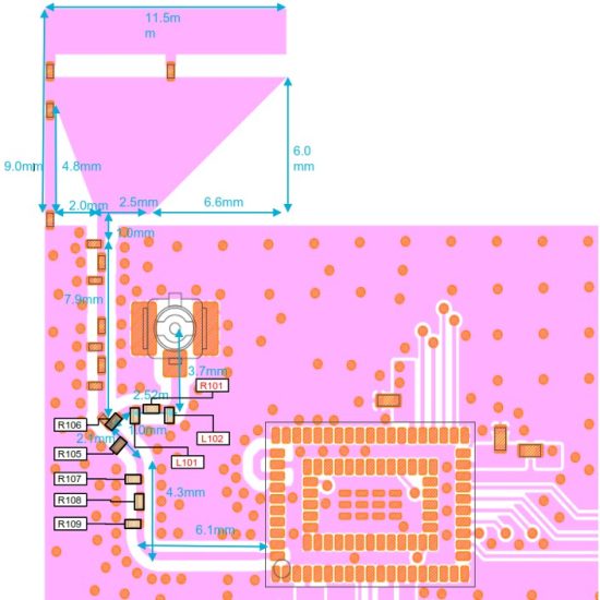 For more detail information, please refer to “P2ML11463_Type2GF_For_DXF.dxf” feed line width : 0.35mm number of substrate layers : 6 Substrate thin : 0.8 ± 0.1 mm
※ If using dipole antenna, please mount the following Attenuator
| Ref# | Value | |
| L102 | 300 | Ω |
| R101 | 16 | Ω |
| L101 | 300 | Ω |
| R106 | 0 | Ω |
| R105 | None | |
| R107 | None | |
| R108 | 0 | Ω |
| R109 | None | |
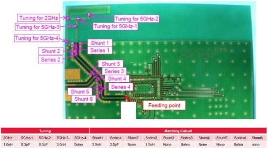
- Monopole antenna(Type1LV_Antenna)
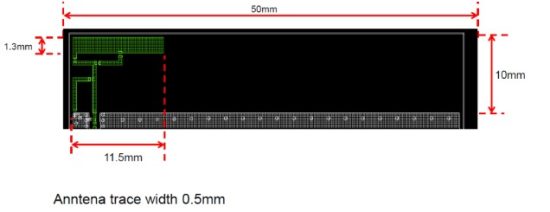 feed line width : 0.35mm number of substrate layers : 6 Substrate thin : 0.8 ± 0.1 mm
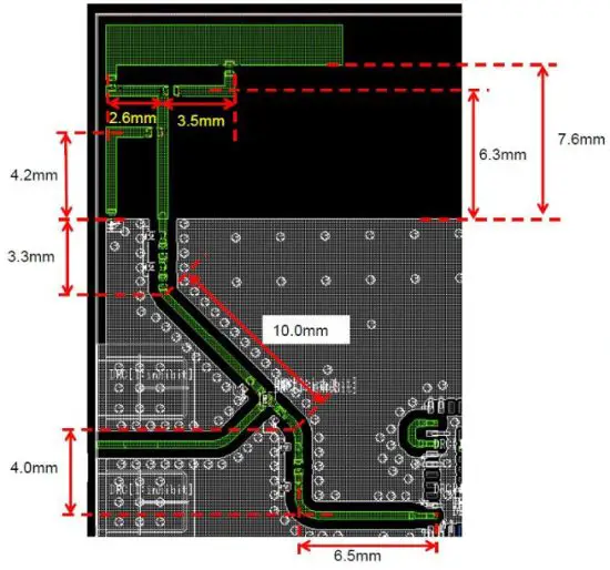
The Layer2 ground plane provides a return path for the circuit.
The Dielectric material (along with the dimensions of the microstrip structures) determines the characteristic impedance of the microstrip transmission line.
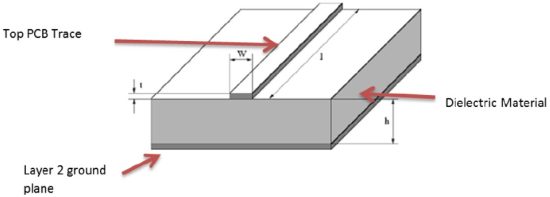
Note the representative dimensions shown in the drawing above.
It is imperative that the module customer (the integrator) use the exact dimensions we recommend to ensure a 50-ohm impedance for this transmission line.
The following dimensions and/or ratios should be used to set the microstrip impedance to 50ohms.
Dielectric (PCB) Material — We recommend standard FR4 PCB material. Other dielectrics will work but will require recalculation of microstrip dimensions.
The following guidance is predicated on the use of FR4 Dielectric.
If FR4 is not used for PCB material, please contact Murata to determine new dimensions for microstrip structure.
H (Dielectric Height) — this is the thickness of dielectric between the trace layer (layer 1) and the ground plane on layer 2.
Note that layer 2 must be electrical ground. We recommend a dielectric thickness of 8-15 mils.
This range provides the customer with some flexibility in board construction.
t (trace thickness) — Microstrip impedance is not severely affected by the thickness dimension.
Standard 102 or 202 copper deposition is recommended. Equivalent thickness is 1-2 mils.
W (trace width) — this is the crucial dimension. This width must be set correctly to obtain the desired 50 ohms impedance.
When using FR-4 dielectric, the width (W) of the microstrip trace should be set to: W = H * 1.8
Copyright © Murata Manufacturing Co., Ltd.
All rights reserved.
Documents / Resources
 |
muRata LBEE5WV2GF Wi-Fi Bluetooth Module [pdf] User Manual VPYLBEE5WV2GF, LBEE5WV2GF Wi-Fi Bluetooth Module, LBEE5WV2GF, Wi-Fi Bluetooth Module, Bluetooth Module, Module |