![]() V3200 Series
V3200 Series
Quick Installation Guide
Embedded Computers
Version 1.0, March 2023
Overview
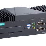
The V3200 Series embedded computers are built around an Intel® Core™ i7/i5/i3 or Intel® Celeron® high-performance processor and come with up to 64 GB RAM, one M.2 2280 M key slot, and two HDD/SSD for storage expansion. The computers are compliant with EN 50155:2017 and EN 50121-4 standards covering operating temperature, power input voltage, surge, ESD, and vibration, making them suitable for railway onboard and wayside applications.
For connecting with onboard and wayside systems and devices, the V3200 computers are equipped with a rich set of interfaces including 4 Gigabit Ethernet ports (default; can go up to 8 ports) with one-pair LAN bypass function to ensure uninterrupted data transmission, 2 RS232/422/485 serial ports, 2 DIs, 2 DOs, and 2 USB 3.0 ports. The builtin TPM 2.0 module ensures platform integrity and provides hardwarebased security as well as protection from tampering.
Vehicular applications require reliable connectivity. They also require clear indicators on the device that identify the status of the software.
The V3200 computers come with two 5G/one LTE and 6 SIM-card slots to help establish redundant LTE/Wi-Fi connections and 3 programmable LEDs that enable monitoring of the runtime status of software.
Package Checklist
Each basic system model package is shipped with following items:
- V3200 Series embedded computer
- Wall-mounting kit
- 2 HDD trays
- 16 screws for securing the HDD trays
- HDMI cable locker
- Quick installation guide (printed)
- Warranty card
NOTE Notify your sales representative if any of the above items are missing or damaged.
Panel Views
Front View
V3200-TL-4L Models 
V3200-TL-8L Models 
Rear View 
Dimensions
V3200-TL-4L Models 
V3200-TL-8L Models 
LED Indicators
The following table describes the LED indicators located on the front and rear panels of the V3200 computer.
| LED Name | Status | Function |
| Power (Power button) |
Green | Power is ON |
| OFF | No power input/other power-input error | |
|
Ethernet |
Green | Steady ON: 100 Mbps Ethernet link Blinking: Data transmission is in progress |
| Yellow | Steady ON: 1000 Mbps Ethernet link Blinking: Data transmission is in progress | |
| Off | Data transmission speed at 10 Mbps or the cable is not connected | |
| Ethernet (1000 Mbps) (2500 Mbps) LAN1 |
Green | Steady ON: 1000 Mbps Ethernet link Blinking: Data transmission is in progress |
| Yellow | Steady ON: 2500 Mbps Ethernet link Blinking: Data transmission is in progress | |
| OFF | Data transmission speed at 100/10 Mbps or the cable is not connected | |
| Serial (TX/RX) |
Green | Tx: Serial port is transmitting data |
| Yellow | Rx: Serial port is receiving data | |
| OFF | No operations | |
| Storage | Yellow | Data is being accessed from either the M.2 M key (PCIe [x4]) or the SATA drive |
| OFF | Data is not being accessed from the storage drives | |
| LAN Bypass LED (I/O board) |
Yellow | LAN bypass mode is activated |
| OFF | No operations | |
| Programmable LED (Main board*3) |
Green | Application active normally, blinking or frequency adjustment |
| OFF | No operations |
Installing the V3200
The V3200 computer comes with 2 wall-mounting brackets. Attach the brackets to the computer using 4 screws on each side. Ensure that the mounting brackets are attached to the V3200 computer in the direction shown in the following figure.  The 8 screws for the mounting brackets are included in the product package. They are standard IMS_M3x5L screws and require a torque of 4.5 kgf-cm. Refer to the following illustration for details.
  Use 2 screws (M3*5L standard is recommended) on each side to attach the V3200 to a wall or cabinet. These 4 screws are not included in the product package; they need to be purchased separately.
Ensure that the V3200 computer is installed in the direction shown in the following figure: 
Connecting the Power
The V3200 computers are provided with M12 power input connectors on the front panel. Connect the power cord wires to the connectors and then tighten the connectors. Push the power button; the Power LED (on the power button) will light up to indicate that power is being supplied to the computer. It should take about 30 to 60 seconds for the operating system to complete the boot-up process.
| Pin | Definition |
| 1 | V+ |
| 2 | N.C. |
| 3 | V- |
| 4 | N.C. |
 The power input specification is given below:
- DC source with a power source rating of 24 V @ 4.0 A; 110 V @ 0.9 A, and a minimum of 18 AWG.
For surge protection, connect the grounding connector located beside the power connector with the earth (ground) or a metal surface.
NOTE This computer is designed to be supplied by listed equipment (UL listed/ IEC 60950-1/ IEC 62368-1) rated 24 to 110VDC, minimum 4 to 0.9 A, and minimum Tma=70˚C. If you need assistance with purchasing a power adapter, contact the Moxa technical support team.
Connecting Displays
The V3200 has 1 VGA interface that comes with a D-Sub 15-pin female connector. In addition, another HDMI interface is also provided on the front panel.
NOTE In order to have highly reliable video streaming, use premium HDMI-certified cables.
USB Ports
The V3200 comes with 2 USB 3.0 ports on the rear panel. The USB ports can be used to connect to peripherals, such as keyboard, mouse, or flash drives for expanding the system’s storage capacity.
Serial Ports
The V3200 comes with 2 software-selectable RS-232/422/485 serial ports on the rear panel. The ports use DB9 male connectors.
Refer to the following table for the pin assignments:
| Pin | RS-232 | RS-422 | RS-485 (4-wire) |
RS-485 (2-wire) |
| 1 | DCD | TxDA(-) | TxDA(-) | – |
| 2 | RxD | TxDB(+) | TxDB(+) | – |
| 3 | TxD | RxDB(+) | RxDB(+) | DataB(+) |
| 4 | DTR | RxDA(-) | RxDA(-) | DataA(-) |
| 5 | GND | GND | GND | GND |
| 6 | DSR | – | – | – |
| 7 | RTS | – | – | – |
| 8 | CTS | – | – | – |

Ethernet Ports
The V3200 has 4 (V3200-TL-4L models) or 8 (V3200-TL-8L models) 1000 Mbps RJ45 Ethernet ports with M12 connectors on the front panel.
Refer to the following table for the pin assignments:
| Pin | Definition |
| 1 | DA+ |
| 2 | DA- |
| 3 | DB+ |
| 4 | DB- |
| 5 | DD+ |
| 6 | DD- |
| 7 | DC- |
| 8 | DC+ |

Digital Inputs/Digital Outputs
The V3200 comes with 2 digital inputs and 2 digital outputs in a terminal block. Refer to the following figures for the pin definitions and the current ratings. 
Digital Inputs Dry Contact
Logic 0: Short to Ground
Logic 1: Open
Wet Contact (COM to DI)
Logic 0: 10 to 30 VDC
Logic 1: 0 to 3 VDC
Digital Outputs
Current Rating: 200 mA per channel
Voltage: 24 to 30 VDC
For detailed wiring methods, refer to the V3200 Hardware User’s Manual.
Installing SIM Cards
The V3200 Series comes with 6 SIM card slots on the rear panel of the computer. Make sure you insert the SIM card in the right direction as indicated on the label.  For detailed SIM card and wireless module installation, refer to the V3200 Hardware User Manual.
Replacing the Battery
The V3200 comes with one slot for a battery, which is installed with a lithium battery with 3V/200 mAh (Type: BR2032) specifications.
To replace the battery, do the following:
- Locate the cover of the battery slot.
The battery slot is located on the front panel of the computer. - Unfasten the two screws on the battery cover.
- Take off the cover; the battery is attached to the cover.
- Separate the connector and remove the two screws on the metal plate.
- Replace the new battery in the battery holder, place the metal plate on the battery, and fasten the two screws tightly.
- Reconnect the connector, place the battery holder into the slot, and secure the cover of the slot by fastening the two screws on the cover.
NOTE Be sure to use the correct type of battery. Incorrect battery may cause system damage. Contact Moxa’s technical support staff for assistance, if necessary.
![]() CAUTION
CAUTION
Dispose of used batteries according to the instructions.
Technical Support Contact Information www.moxa.com/support
![]() © 2023 Moxa Inc. All rights reserved.
© 2023 Moxa Inc. All rights reserved.
P/N: 1802030000001
![]()
Documents / Resources
 |
MOXA V3200 Series Embedded Computers [pdf] Installation Guide V3200 Series Embedded Computers, V3200 Series, Embedded Computers, Computers |
 |
MOXA V3200 Series Embedded Computers [pdf] Installation Guide V3200-TL-4L, V3200-TL-8L, V3200 Series Embedded Computers, V3200 Series, Embedded Computers, Computers |