Mircom MIX-M500MAP Monitor Module
SPECIFICATIONS
- Normal Operating Voltage: 15 to 32 VDC
- Maximum Alarm Current (LED on): 5.0mA (LED on)
- Average Operating Current: 400 μA, 1 communication every 5 seconds, 47k
- EOL EOL Resistance: 47K Ohms
- Maximum IDC wiring resistance: 40 Ohms
- Maximum IDC Voltage: 11 Volts
- Maximum IDC Current: 400µA
- Temperature Range: 32˚F to 120˚F (0˚C to 49˚C)
- Humidity: 10% to 93% Non-condensing
- Dimensions: 41/2˝ H x 4˝ W x 11/4˝ D (Mounts to a 4˝ square by 21/8˝ deep box.)
- Accessories: SMB500 Electrical Box
BEFORE INSTALLING
This information is included as a quick reference installation guide. Refer to the control panel installation manual for detailed system information. If the modules will be installed in an existing operational system, inform the opera-tor and local authority that the system will be temporarily out of service. Dis-connect power to the control panel before installing the modules.
NOTICE: This manual should be left with the owner/user of this equipment.
GENERAL DESCRIPTION
The MIX-M500MAP Monitor Module is intended for use in intelligent, two-wire systems, where the individual address of each module is selected using the built-in rotary decade switches. It provides either a 2-wire or 4-wire fault tolerant initiating circuit for normally open contact fire alarm, supervisory, or security devices. The module has a panel controlled LED indicator.
COMPATIBILITY REQUIREMENTS
To ensure proper operation, these modules shall be connected to listed com-patible system control panels only.

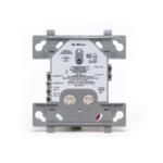
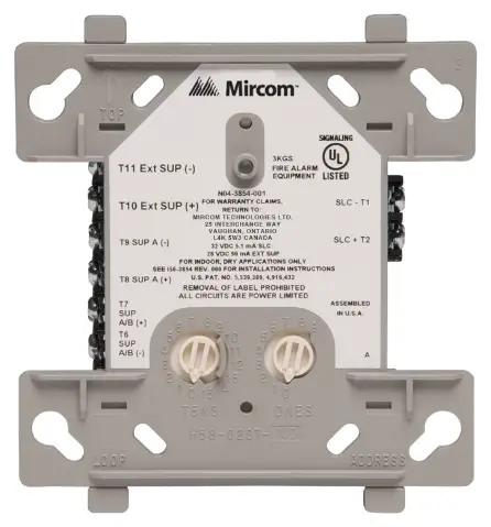
MOUNTING
The MIX-M500MAP mounts directly to 4-inch square electrical boxes (see Figure 2). The box must have a minimum depth of 21/8 inches. Surface mounted electrical boxes (SMB500) are available from System Sensor.
FIGURE 2. MODULE MOUNTING:

WIRING
NOTE: All wiring must conform to applicable local codes, ordinances, and regulations. This module is intended for power limited wiring only.
- Install module wiring in accordance with the job drawings and appropri-ate wiring diagrams.
- Set the address on the module per job drawings.
- Secure module to electrical box (supplied by installer), as shown in Fig-ure 2.


Documents / Resources
 |
Mircom MIX-M500MAP Monitor Module [pdf] Installation Guide MIX-M500MAP Monitor Module, MIX-M500MAP, Monitor Module, Module |