MICROCHIP SAMRH71 Programming the External Memory Family Evaluation Kits
Specifications
- Product Name: SAMRH Family Evaluation Kits
- External Memory: Flash Memory
- Memory Devices:
- SAMRH71F20-EK:
- Memory Device: SST39VF040
- Size: 4 Mbit
- Organized as: 512K x 8
- Mapped from: 0x6000_0000 to 0x6007_FFFF
- SAMRH71F20-TFBGA-EK:
- Memory Device: SST38VF6401
- Size: 64 Mbit
- Organized as: 4M x 16
- Mapped from: 0x6000_0000 to 0x607F_FFFF
- SAMRH707F18-EK:
- Memory Device: SST39VF040
- Size: 4 Mbit
- Organized as: 512K x 8
- Mapped from: 0x6007_FFFF
- SAMRH71F20-EK:
Product Usage Instructions
Prerequisites
This example runs on the versions listed below:
External Boot Memory Implementation
The SAMRH evaluation boards contain external flash memories connected to the NCS0 chip-select signals. NCS0 is configured in the HEMC to the 0x6000_0000 memory area at reset. This memory area can be mirrored to the Boot memory address via BOOT_MODE selection pins.
Memory Devices Features
The following table provides details about external flash memory for each evaluation kit:
| Evaluation Kits | Memory Devices | Size | Organised as | Mapped from | Mapped to |
|---|---|---|---|---|---|
| SAMRH71F20-EK | SST39VF040 | 4 Mbit | 512K x 8 | 0x6000_0000 | 0x6007_FFFF |
Hardware Settings
This section provides the DIP switch configurations for the processor to boot from external memory.
SAMRH71F20-EK DIP Switch Configuration
The processor boots from external flash memory with a configurable data bus width set to 8-bit.
FAQ
Q: How do I know if my board is configured to boot from external memory?
A: Check the DIP switch settings according to the provided configurations in the user manual. Ensure the data bus width is correctly set for your evaluation kit.
Programming the External Memory of SAMRH Family Evaluation Kits using MPLAB-X with SAMBA Memory Handlers
Introduction
This application note explains how to make MPLAB-X IDE capable of programing and debugging the external boot memory embedded in the SAMRH family evaluation kits. This capability is provided by SAMBA Memory Handlers that are called from MPLAB-X IDE.
This document briefly describes the steps to set up MPLAB-X IDE projects that need to run from the external memory. Projects can be created from scratch or built from existing ones.
Prerequisites
This example runs on the versions listed below:
- MPLAB v6.15, or later versions
- SAMRH71 DFP packs v2.6.253, or later versions
- SAMRH707 DFP pack v1.2.156, or later versions
External Boot Memory Implementation
The SAMRH evaluation boards contain external flash memories which are connected to the NCS0 chip-select signals. NCS0 is configured in the HEMC to the 0x6000_0000 memory area at reset. This 0x6000_0000 memory area can be selected to be mirrored to the 0x0000_0000 Boot memory address via the BOOT_MODE selection pins at reset, see the relevant device datasheets.
The following table provides details about external flash memory for each evaluation kit.
Table 2-1. Memory Devices Features
| Evaluation Kits | SAMRH71F20-EK | SAMRH71F20-TFBGA-EK | SAMRH707F18-EK |
| Memory Devices | SST39VF040 | SST38VF6401 | SST39VF040 |
| Size | 4 Mbit | 64 Mbit | 4 Mbit |
| Organised as | 512K x 8 | 4M x 16 | 512K x 8 |
| Mapped from | 0x6000_0000 | ||
| To | 0x6007_FFFF | 0x607F_FFFF | 0x6007_FFFF |
The supplied SAMBA memory handlers have been developed to load data and code into these external flash memory devices while complying with the conditions exposed in the table above.
Hardware Settings
This section provides the DIP switch configurations that must be applied to the boards for the processor to boot from the external memory. The DIP switch configuration has been implemented according to the following convention:
- The OFF position generates a logic 1
- The ON position generates a logic 0
SAMRH71F20-EK
On this kit the processor boots from external flash memory with a configurable data bus width that must be set to 8-bit.
The following table provides details about complete setting of the DIP switch.
Table 3-1. SAMRH71F20-EK Settings
| SAMRH71F20 Processor | SAMRH71F20 EK | ||||
| Pin Numbers | Pin Names | Function | Options | Selection | Required Configuration |
| PF24 | Boot Mode | Selects the memory boot | 0: Internal Flash | External Flash | SW5-1 = 1 (OFF) |
| 1: External Flash | |||||
| PG24 | CFG0 | Selects the data bus width just for NSC0 chip select | CFG[1:0] = 00: 8 bit | 8 bit | SW5-2 = 0 (ON) |
| CFG[1:0] = 01: 16 bit | |||||
| PG25 | CFG1 | CFG[1:0] = 10: 32 bit | SW5-3 = 0 (ON) | ||
| CFG[1:0] = 11:
reserved |
|||||
| PG26 | CFG2 | Selects the HECC activation/ deactivation for all NCSx | 0: HECC Off | HECC Off | SW5-4 = 0 (ON) |
| 1: HECC On | |||||
| PC27 | CFG3 | Selects the HECC code corrector applied for all NCSx | 0: Hamming | Hamming | SW5-5 = 0 (ON) |
| 1: BCH | |||||
| Not Connected | SW5-6 = “Don’t care” | ||||

SAMRH71F20 – TFBGA – EK
On this kit the processor boots from external flash memory with a configurable data bus width that has been hard-wired to 16-bit.
The following table provides details about complete setting of the DIP switch.
Table 3-2. SAMRH71F20-TFBGA-EK Settings
| SAMRH71F20 Processor | SAMRH71F20-TFBGA EK | |||||
| Pin Numbers | Pin Names | Function | Options | Selection | Required Configuration | |
| PF24 | Boot Mode | Selects the memory boot | 0: Internal Flash | External Flash | SW4-1 = 1 (OFF) | |
| 1: External Flash | ||||||
| PG26 | CFG2 | Selects the HECC activation/ deactivation for all NCSx | 0: HECC Off | HECC Off | SW4-2 = 0 (ON) | |
| 1: HECC On | ||||||
| PC27 | CFG3 | Selects the HECC code corrector applied for all NCSx | 0: Hamming | Hamming | SW4-3 = 0 (ON) | |
| 1: BCH | ||||||
| PG24 | CFG0 | Selects the data bus width just for NSC0 chip select | CFG[1:0] = 00: 8 bit | 16 bit |
Hard Wired |
PG24 = 1 (OFF) |
| CFG[1:0] = 01: 16
bit |
||||||
| PG25 | CFG1 | CFG[1:0] = 10: 32
bit |
PG25 = 0 (ON) | |||
 Note:
Note:
“1” and “0” are inverted on the silkscreen of the board.
SAMRH707F18 – EK
On this kit the processor boots from external flash memory with a fixed 8-bit data bus width. The following table provides details about complete setting of the DIP switch.
Table 3-3. SAMRH707F18-EK Settings
| SAMRH707F18 Processor | SAMRH707F18-EK | |||||
| Pin Numbers | Pin Names | Function | Options | Selection | Required Configuration | |
| PC30 | Boot Mode 0 | Selects the boot memory | Boot Mode [1:0] = 00: Internal Flash (HEFC) | External Flash | SW7-1 = 1 (OFF) | |
| Boot Mode [1:0 ] = 01: External Flash (HEMC) | ||||||
| PC29 | Boot Mode 1 | Boot Mode [1:0] = 1X: Internal ROM | SW7-2 = 0 (ON) | |||
| PA19 | CFG3 | Boot Mode [1:0] = 01 (External Flash) | N/A | SW7-3 = “Don’t care” | ||
| Hamming code selected by default as HECC code corrector for all NCSx | Internally driven to ‘0’ | |||||
| Boot Mode [1:0] = 1X (Internal ROM) | ||||||
| Selects the active phase when the internal ROM is active | 0: Run Phase | |||||
| 1: Maintenance Phase | ||||||
| PA25 | CFG2 | Boot Mode [1:0] = 01 (External Flash) | HECC Off | SW7-4 = 0 (ON) | ||
| Selects the HECC activation / deactivation for all NCSx when External Flash is active | 0: HECC Off | |||||
| 1: HECC On | ||||||
| Boot Mode [1:0] = 1X (Internal ROM) | ||||||
| Selects the communication mode when the Internal ROM is active | 0: UART Mode | |||||
| 1: SpaceWire Mode | Boot Mode 0 = 0 | |||||
| LVDS Interface | ||||||
| Boot Mode 0 = 1 | ||||||
| TTL Mode | ||||||
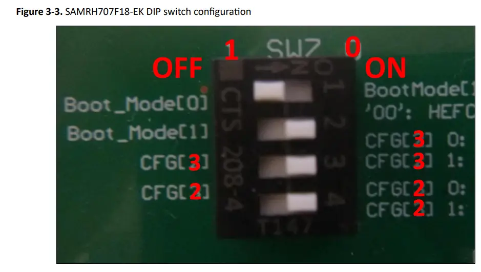 Note:
Note:
“CFG[2]” and “CFG[3]” are inverted on the silkscreen of the board.
Software Settings
The following section explains how to configure MPLAB X projects to run from external memory.
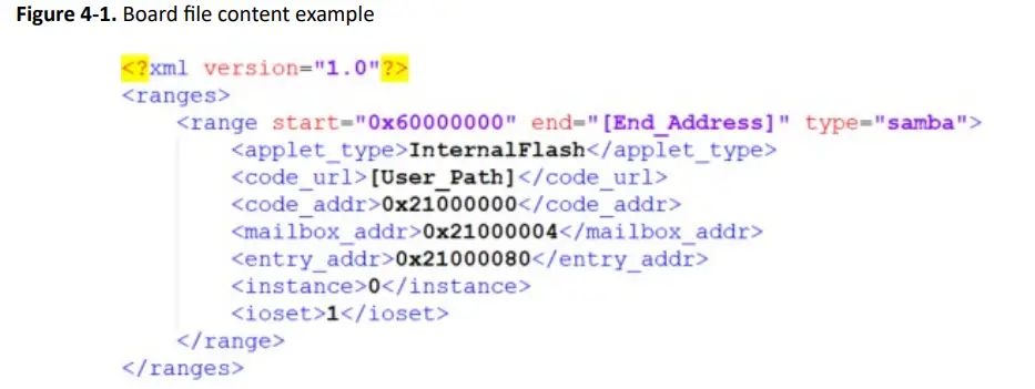
Board file
The board file is an XML file with the extension (*.xboard) that describes the parameters passed to SAMBA memory handlers. It must be placed in the user’s MPLAB-X project folder.
For the SAMRH evaluation kits, the default name of the board file is “board.xboard”, and its default location is the root folder of the project: “ProjectDir.X”
Two parameters contained in the board file must be configured by the user to make the file compliant with the structure of the user’s application.
These two parameters are:
- [End_Address]: This parameter is related to the external boot memory size and defines the memory’s last address.
- [User_Path]: This parameter defines the absolute path of SAMBA memory handlers’ location.
The other parameters depend on SAMBA memory handler’s implementation and can be kept at their default values.
The following figure provides a structure example of the board file.
Figure 4-1. Board file content example
 The following table provides the default user parameters of the board files supplied for the SAMRH evaluation kits.
Table 4-1. Board File Parameters
| SAMRH Evaluation Kit | [End_Address] | [User_Path] |
| SAMRH71F20-EK | 6007_FFFFh | ${ProjectDir}\sst39vf040_loader_samba_sam_rh71_ek_sram.bin |
| SAMRH71F20-TFGBA EK | 607F_FFFFh | ${ProjectDir}\sst38vf6401_loader_samba_sam_rh71_tfbga_sram.bin |
| SAMRH707F18-EK | 6007_FFFFh | ${ProjectDir}\sst39vf040_loader_samba_sam_rh707_ek_sram.bin |
Project Configuration
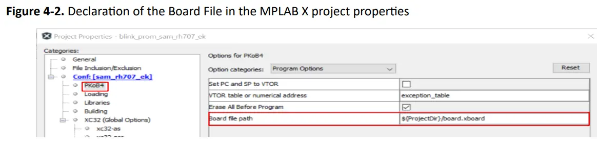
Board File
The board file must be defined in the “Board file path” field of the project properties of MPLAB X projects, as shown in the following figure. “Board file path” field is accessible from the debugger tool options (PKoB4 in our example), then “Program Options” is selected from the “Option Categories” menu.
By default, the board file path field is set to: ${ProjectDir}/board.xboard If the board file is not present in the folder, SAMBA memory handlers are ignored.
Figure 4-2. Declaration of the Board File in the MPLAB X project properties
External Memory
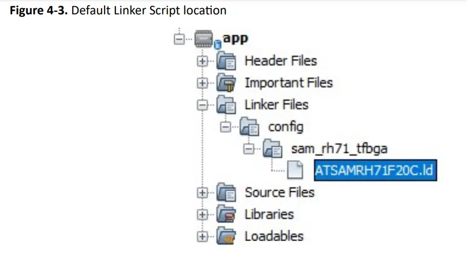
MPLAB-X Harmony 3 (MH3) sample projects use a default linker script that configures the application to run from internal boot memory.
By default, the linker script file “ATSAMRH71F20C.ld” is implemented in harmony projects, as shown in the following figure.
Figure 4-3. Default Linker Script location
The linker script uses the internal parameters ROM_ORIGIN and ROM_LENGTH, as shown in the following figure, to define the location and length of the boot memory. The application depends on these parameters to create the executable.
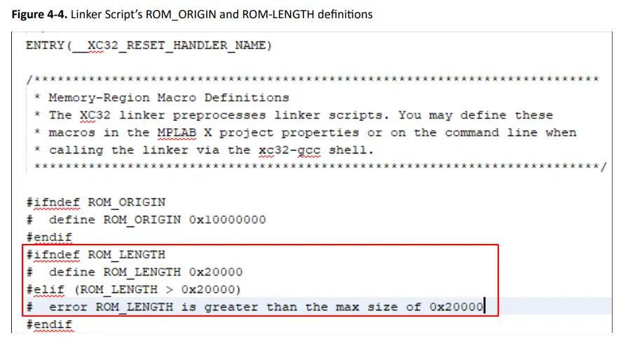 The sample linker script above limits the parameter ROM_LENGTH to 0x0002_0000 which is the length of the internal flash and generates a compilation error if this condition is not met.
However, this limitation may not be compliant with the use of the external flash memory, as its length could be greater than 0x0002_0000.
If the code programmed in the external memory is smaller than 0x0002_0000, there is no need to update the linker script file. However, if it exceeds this length, the ROM_LENGTH parameter should be updated to reflect the actual length of the external memory.
The ROM_ORIGIN parameter can also be overridden without modifying the linker script file.
Before overriding the ROM_LENGTH parameter, the linker script must be edited to match your hardware configuration.
To override the ROM_LENGTH parameter, you can use the “Preprocessor macro definitions” field in the MPLAB-X project properties. This field can be accessed from the “XC32-ld” item, and then
“Symbols & Macros” can be selected from the “Options Categories” menu, as shown in the following figure.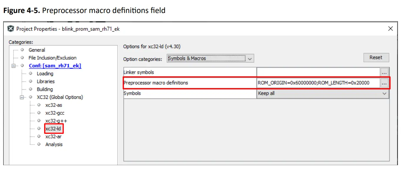
For example, for the SST39VF040 flash memory device:
If the ROM_LENGTH has not been modified and the built code length should be smaller than 0x0002_0000.
- ROM_LENGTH=0x20000
- ROM_ORIGIN=0x60000000
If the ROM_LENGTH has been updated to 0x0008_0000 and the built code length should be smaller than 0x0005_0000.
- ROM_LENGTH=0x50000
- ROM_ORIGIN=0x60000000
Software Deliveries
SAMBA memory handlers’ mechanism is based on binary applets, which differ according to the processor version and the external boot memory implemented. There are three binary applets specific to the SAMRH evaluation kits:
- sst39vf040_loader_samba_sam_rh71_ek_sram.bin
- sst39vf040_loader_samba_sam_rh707_ek_sram.bin
- sst38vf6401_loader_samba_sam_rh71_tfbga_sram.bin
These applets run in the processor’s internal RAM and include both the SAMBA interface for communicating with debug scripts and the routines that perform programming operations (erase, write, and so on) on external boot memory.
Three zipped software packages are supplied to support the SAMRH evaluation kits. Each package includes:
- The dedicated board file
- The dedicated binary applet file.
Compiling, Programming, and Debugging from the External Boot Memory
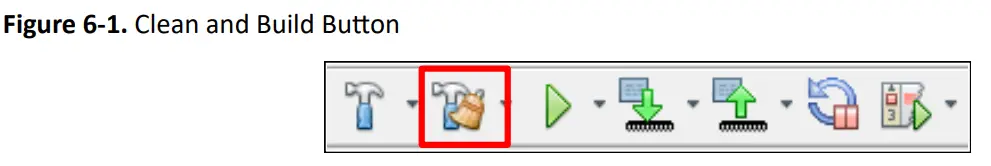
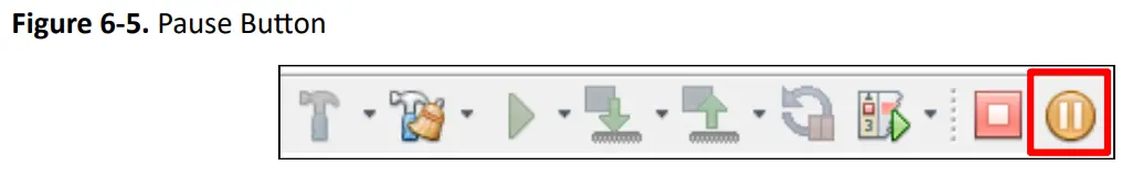
Once the MPLAB X project has been completely setup with a valid SAMBA memory handler, user can compile, program, and debug this project in the external boot memory using the buttons and icon bar from the top menu, as shown in the following figures.
- To clean and compile the project, click the Clean and Build.
- To program the application to the device, click the Make and Program.
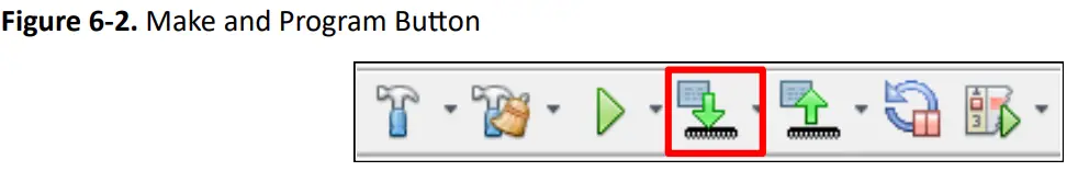
- To run the code, click the Debug Project.
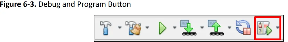
- To stop the code, click the Finish Debugger Session.
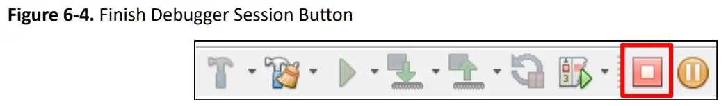
- Or to pause it, click the Pause.
- Or to pause it, click the Pause.
Reference
This section lists documents that provide more information about the MPLAB X, SAMRH71 and SAMRH707 devices.
MPLAB X
MPLAB X IDE User’s Guide, DS50002027D. https://www.microchip.com/en-us/tools-resources/develop/mplab-x-ide#tabs
SAMRH71 Device
- SAMRH71F20 Device Datasheet, DS60001593 ww1.microchip.com/downloads/en/DeviceDoc/SAMRH71_Datasheet_DS60001593F.pdf
- SAMRH71F20 Evaluation Kit User Guide, DS50002910. https://ww1.microchip.com/downloads/en/DeviceDoc/SAMRH71F20-EK-Evaluation-Kit-User-Guide-DS50002910A.pdf
- SAMRH71-TFBGA-EK Evaluation Kit User Guide, DS50003449A https://ww1.microchip.com/downloads/aemDocuments/documents/AERO/ProductDocuments/UserGuides/50003449.pdf
- Getting started with SAMRH71F20 Evaluation Kit, DS00004008. https://ww1.microchip.com/downloads/en/Appnotes/
- Getting_Started_with_the_SAMRH71F20_Evaluation_Kit_DS00004008A.pdf
- SST38LF6401RT and SAMRH71 Reference Design, DS0004274 https://ww1.microchip.com/downloads/aemDocuments/documents/AERO/ApplicationNotes/ApplicationNotes/AN4274_SST38LF6401RT_SAMRH71_Reference_Design_00004274.pdf
SAMRH707 Device
SAMRH707F18 Device Datasheet, DS60001634 https://ww1.microchip.com/downloads/aemDocuments/documents/AERO/ProductDocuments/DataSheets/SAMRH707_Datasheet_DS60001634.pdf
Getting Started with SAMRH707F18 Microcontroller using MPLAB-X IDE and MCC Harmony Framework, DS00004478 https://ww1.microchip.com/downloads/aemDocuments/documents/AERO/ApplicationNotes/ApplicationNotes/00004478.pdf
SAMRH707-EK Evaluation Kit User Guide, DS60001744
https://ww1.microchip.com/downloads/aemDocuments/documents/AERO/ProductDocuments/UserGuides/SAMRH707_EK_Evaluation_Kit_User_Guide_60001744.pdf
SST38LF6401RT and SAMRH707 Reference Design, DS00004583 ww1.microchip.com/downloads/aemDocuments/documents/AERO/ApplicationNotes/ApplicationNotes/SAMRH707-SST38LF6401RT-Reference-Design-00004583.pdf
Revision History
The revision history describes the changes that were implemented in the document. The changes are listed by revision, starting with the most current publication.
| Revision | Date | Description |
| A | 04/2024 | Initial Revision |
Microchip Information
The Microchip Website
Microchip provides online support via our website at www.microchip.com/. This website is used to make files and information easily available to customers. Some of the content available includes:
- Product Support – Data sheets and errata, application notes and sample programs, design resources, user’s guides and hardware support documents, latest software releases and archived software
- General Technical Support – Frequently Asked Questions (FAQs), technical support requests, online discussion groups, Microchip design partner program member listing
- Business of Microchip – Product selector and ordering guides, latest Microchip press releases, listing of seminars and events, listings of Microchip sales offices, distributors and factory representatives
Product Change Notification Service
Microchip’s product change notification service helps keep customers current on Microchip products. Subscribers will receive email notification whenever there are changes, updates, revisions or errata related to a specified product family or development tool of interest.
To register, go to www.microchip.com/pcn and follow the registration instructions.
Customer Support
Users of Microchip products can receive assistance through several channels:
- Distributor or Representative
- Local Sales Office
- Embedded Solutions Engineer (ESE)
- Technical Support
Customers should contact their distributor, representative or ESE for support. Local sales offices are also available to help customers. A listing of sales offices and locations is included in this document.
Technical support is available through the website at: www.microchip.com/support
Microchip Devices Code Protection Feature
Note the following details of the code protection feature on Microchip products:
- Microchip products meet the specifications contained in their particular Microchip Data Sheet.
- Microchip believes that its family of products is secure when used in the intended manner, within operating specifications, and under normal conditions.
- Microchip values and aggressively protects its intellectual property rights. Attempts to breach the code protection features of Microchip product is strictly prohibited and may violate the Digital Millennium Copyright Act.
- Neither Microchip nor any other semiconductor manufacturer can guarantee the security of its code. Code protection does not mean that we are guaranteeing the product is “unbreakable”. Code protection is constantly evolving. Microchip is committed to continuously improving the code protection features of our products.
Legal Notice
This publication and the information herein may be used only with Microchip products, including to design, test, and integrate Microchip products with your application. Use of this information in any other manner violates these terms. Information regarding device applications is provided only for your convenience and may be superseded by updates. It is your responsibility to ensure that your application meets with your specifications. Contact your local Microchip sales office for additional support or, obtain additional support at www.microchip.com/en-us/support/design-help/client-support-services.
THIS INFORMATION IS PROVIDED BY MICROCHIP “AS IS”. MICROCHIP MAKES NO REPRESENTATIONS OR WARRANTIES OF ANY KIND WHETHER EXPRESS OR IMPLIED, WRITTEN OR ORAL, STATUTORY OR OTHERWISE, RELATED TO THE INFORMATION INCLUDING BUT NOT LIMITED TO ANY IMPLIED WARRANTIES OF NON-INFRINGEMENT, MERCHANTABILITY, AND FITNESS FOR A PARTICULAR PURPOSE, OR WARRANTIES RELATED TO ITS CONDITION, QUALITY, OR PERFORMANCE.
IN NO EVENT WILL MICROCHIP BE LIABLE FOR ANY INDIRECT, SPECIAL, PUNITIVE, INCIDENTAL, OR CONSEQUENTIAL LOSS, DAMAGE, COST, OR EXPENSE OF ANY KIND WHATSOEVER RELATED TO THE INFORMATION OR ITS USE, HOWEVER CAUSED, EVEN IF MICROCHIP HAS BEEN ADVISED OF THE POSSIBILITY OR THE DAMAGES ARE FORESEEABLE. TO THE FULLEST EXTENT ALLOWED BY LAW, MICROCHIP’S TOTAL LIABILITY ON ALL CLAIMS IN ANY WAY RELATED TO THE INFORMATION OR ITS USE WILL NOT EXCEED THE AMOUNT OF FEES, IF ANY, THAT YOU HAVE PAID DIRECTLY TO MICROCHIP FOR THE INFORMATION.
Use of Microchip devices in life support and/or safety applications is entirely at the buyer’s risk, and the buyer agrees to defend, indemnify and hold harmless Microchip from any and all damages, claims, suits, or expenses resulting from such use. No licenses are conveyed, implicitly or otherwise, under any Microchip intellectual property rights unless otherwise stated.
Trademarks
The Microchip name and logo, the Microchip logo, Adaptec, AVR, AVR logo, AVR Freaks, BesTime, BitCloud, CryptoMemory, CryptoRF, dsPIC, flexPWR, HELDO, IGLOO, JukeBlox, KeeLoq, Kleer, LANCheck, LinkMD, maXStylus, maXTouch, MediaLB, megaAVR, Microsemi, Microsemi logo, MOST, MOST logo, MPLAB, OptoLyzer, PIC, picoPower, PICSTART, PIC32 logo, PolarFire, Prochip Designer, QTouch, SAM-BA, SenGenuity, SpyNIC, SST, SST Logo, SuperFlash, Symmetricom, SyncServer, Tachyon, TimeSource, tinyAVR, UNI/O, Vectron, and XMEGA are registered trademarks of Microchip Technology Incorporated in the U.S.A. and other countries.
AgileSwitch, ClockWorks, The Embedded Control Solutions Company, EtherSynch, Flashtec, Hyper Speed Control, HyperLight Load, Libero, motorBench, mTouch, Powermite 3, Precision Edge, ProASIC, ProASIC Plus, ProASIC Plus logo, Quiet-Wire, SmartFusion, SyncWorld, TimeCesium, TimeHub, TimePictra, TimeProvider, and ZL are registered trademarks of Microchip Technology Incorporated in the U.S.A.
Adjacent Key Suppression, AKS, Analog-for-the-Digital Age, Any Capacitor, AnyIn, AnyOut, Augmented Switching, BlueSky, BodyCom, Clockstudio, CodeGuard, CryptoAuthentication, CryptoAutomotive, CryptoCompanion, CryptoController, dsPICDEM, dsPICDEM.net, Dynamic Average Matching, DAM, ECAN, Espresso T1S, EtherGREEN, EyeOpen, GridTime, IdealBridge,
IGaT, In-Circuit Serial Programming, ICSP, INICnet, Intelligent Paralleling, IntelliMOS, Inter-Chip Connectivity, JitterBlocker, Knob-on-Display, MarginLink, maxCrypto, maxView, memBrain, Mindi, MiWi, MPASM, MPF, MPLAB Certified logo, MPLIB, MPLINK, mSiC, MultiTRAK, NetDetach, Omniscient Code Generation, PICDEM, PICDEM.net, PICkit, PICtail, Power MOS IV, Power MOS 7, PowerSmart, PureSilicon, QMatrix, REAL ICE, Ripple Blocker, RTAX, RTG4, SAM-ICE, Serial Quad I/O, simpleMAP, SimpliPHY, SmartBuffer, SmartHLS, SMART-I.S., storClad, SQI, SuperSwitcher, SuperSwitcher II, Switchtec, SynchroPHY, Total Endurance, Trusted Time, TSHARC, Turing, USBCheck, VariSense, VectorBlox, VeriPHY, ViewSpan, WiperLock, XpressConnect, and ZENA are trademarks of Microchip Technology Incorporated in the U.S.A. and other countries.
SQTP is a service mark of Microchip Technology Incorporated in the U.S.A.
The Adaptec logo, Frequency on Demand, Silicon Storage Technology, and Symmcom are registered trademarks of Microchip Technology Inc. in other countries.
GestIC is a registered trademark of Microchip Technology Germany II GmbH & Co. KG, a subsidiary of Microchip Technology Inc., in other countries.
All other trademarks mentioned herein are property of their respective companies.
© 2024, Microchip Technology Incorporated and its subsidiaries. All Rights Reserved.
ISBN: 978-1-6683-4401-9
Quality Management System
For information regarding Microchip’s Quality Management Systems, please visit www.microchip.com/quality.
Worldwide Sales and Service
| AMERICAS | ASIA/PACIFIC | ASIA/PACIFIC | EUROPE |
| Corporate Office
2355 West Chandler Blvd. Chandler, AZ 85224-6199 Tel: 480-792-7200 Fax: 480-792-7277 Technical Support: www.microchip.com/support Web Address: www.microchip.com Atlanta Duluth, GA Tel: 678-957-9614 Fax: 678-957-1455 Austin, TX Tel: 512-257-3370 Boston Westborough, MA Tel: 774-760-0087 Fax: 774-760-0088 Chicago Itasca, IL Tel: 630-285-0071 Fax: 630-285-0075 Dallas Addison, TX Tel: 972-818-7423 Fax: 972-818-2924 Detroit Novi, MI Tel: 248-848-4000 Houston, TX Tel: 281-894-5983 Indianapolis Noblesville, IN Tel: 317-773-8323 Fax: 317-773-5453 Tel: 317-536-2380 Los Angeles Mission Viejo, CA Tel: 949-462-9523 Fax: 949-462-9608 Tel: 951-273-7800 Raleigh, NC Tel: 919-844-7510 New York, NY Tel: 631-435-6000 San Jose, CA Tel: 408-735-9110 Tel: 408-436-4270 Canada – Toronto Tel: 905-695-1980 Fax: 905-695-2078 |
Australia – Sydney
Tel: 61-2-9868-6733 China – Beijing Tel: 86-10-8569-7000 China – Chengdu Tel: 86-28-8665-5511 China – Chongqing Tel: 86-23-8980-9588 China – Dongguan Tel: 86-769-8702-9880 China – Guangzhou Tel: 86-20-8755-8029 China – Hangzhou Tel: 86-571-8792-8115 China – Hong Kong SAR Tel: 852-2943-5100 China – Nanjing Tel: 86-25-8473-2460 China – Qingdao Tel: 86-532-8502-7355 China – Shanghai Tel: 86-21-3326-8000 China – Shenyang Tel: 86-24-2334-2829 China – Shenzhen Tel: 86-755-8864-2200 China – Suzhou Tel: 86-186-6233-1526 China – Wuhan Tel: 86-27-5980-5300 China – Xian Tel: 86-29-8833-7252 China – Xiamen Tel: 86-592-2388138 China – Zhuhai Tel: 86-756-3210040 |
India – Bangalore
Tel: 91-80-3090-4444 India – New Delhi Tel: 91-11-4160-8631 India – Pune Tel: 91-20-4121-0141 Japan – Osaka Tel: 81-6-6152-7160 Japan – Tokyo Tel: 81-3-6880- 3770 Korea – Daegu Tel: 82-53-744-4301 Korea – Seoul Tel: 82-2-554-7200 Malaysia – Kuala Lumpur Tel: 60-3-7651-7906 Malaysia – Penang Tel: 60-4-227-8870 Philippines – Manila Tel: 63-2-634-9065 Singapore Tel: 65-6334-8870 Taiwan – Hsin Chu Tel: 886-3-577-8366 Taiwan – Kaohsiung Tel: 886-7-213-7830 Taiwan – Taipei Tel: 886-2-2508-8600 Thailand – Bangkok Tel: 66-2-694-1351 Vietnam – Ho Chi Minh Tel: 84-28-5448-2100 |
Austria – Wels
Tel: 43-7242-2244-39 Fax: 43-7242-2244-393 Denmark – Copenhagen Tel: 45-4485-5910 Fax: 45-4485-2829 Finland – Espoo Tel: 358-9-4520-820 France – Paris Tel: 33-1-69-53-63-20 Fax: 33-1-69-30-90-79 Germany – Garching Tel: 49-8931-9700 Germany – Haan Tel: 49-2129-3766400 Germany – Heilbronn Tel: 49-7131-72400 Germany – Karlsruhe Tel: 49-721-625370 Germany – Munich Tel: 49-89-627-144-0 Fax: 49-89-627-144-44 Germany – Rosenheim Tel: 49-8031-354-560 Israel – Ra’anana Tel: 972-9-744-7705 Italy – Milan Tel: 39-0331-742611 Fax: 39-0331-466781 Italy – Padova Tel: 39-049-7625286 Netherlands – Drunen Tel: 31-416-690399 Fax: 31-416-690340 Norway – Trondheim Tel: 47-72884388 Poland – Warsaw Tel: 48-22-3325737 Romania – Bucharest Tel: 40-21-407-87-50 Spain – Madrid Tel: 34-91-708-08-90 Fax: 34-91-708-08-91 Sweden – Gothenberg Tel: 46-31-704-60-40 Sweden – Stockholm Tel: 46-8-5090-4654 UK – Wokingham Tel: 44-118-921-5800 Fax: 44-118-921-5820 |
Application Note
© 2024 Microchip Technology Inc. and its subsidiaries
Documents / Resources
 |
MICROCHIP SAMRH71 Programming the External Memory Family Evaluation Kits [pdf] User Guide SAMRH71, SAMRH71 Programming the External Memory Family Evaluation Kits, Programming the External Memory Family Evaluation Kits, External Memory Family Evaluation Kits, Family Evaluation Kits, Evaluation Kits, Kits |


