MICROCHIP MPLAB ICD 5 In Circuit Debugger

Install the Latest Software
Download the MPLAB® X Integrated Development Environment (IDE) software V6.10 or higher from www.microchip.com/mplabx and install onto your computer. The installer automatically loads the USB drivers. Launch MPLAB X IDE.
Connect to Target Device
- Connect the MPLAB ICD 5 to the computer using a USB cable.
- If you will be using Ethernet communication a Power Over Ethernet injector is mandatory. Connect external power* to the target board if not using debugger power.
IMPORTANT NOTE: A USB connection is required at first to setup Ethernet communication.
Computer Connections

Target Connections

*External target board power supply provided by user.
Additional resources found in section 10.6.1 of the user’s guide
Set Up Ethernet
To configure MPLAB ICD 5 for Ethernet, go to Project Properties > Manage Network Tools in MPLAB X IDE.

Use the following steps to set up your selected computer connection.
Set Up Ethernet
| Ethernet Setup and Tool Discovery in MPLAB X IDE | |
| 1 | Connect the device to your PC via the USB cable. If you will be using Ethernet communication, a PoE injector is mandatory. |
| 2 | Go to Tools> Manage Network Tools in MPLAB® X IDE. |
| 3 | Under “Network Capable Tools Plugged into USB,” select your debugger. |
| 4 | Under “Configure Default Connection Type for Selected Tool” select the radio button for the connection you want. Ethernet (Wired/Static IP): Input Static IP Address, Subnet Mask and Gateway. Click Update Connection Type. |
| 5 | If Ethernet communication was chosen, ensure the PoE injector is connected and then unplug the USB cable from your debugger unit. |
| 6 | The debugger will restart automatically and come up in the connection mode you selected. Then: The LEDs will display for either a successful network connection or a network connection failure/error. |
| 7 | Now go back to the “Manage Network Tools” dialog and click on the Scan button, which will list your debugger under “Active Discovered Network Tools.” Select the checkbox for your tool and close the dialog. |
| 8 | If your debugger is not found under “Active Discovered Network Tools,” you can manually enter information in the “User Specified Network Tools” section. You must know the IP address of the tool (by the way of network admin or static IP assignment). |
Connect to a Target
See the table below for the pin-out of the 8-pin connector on your target. It is recommended that you connect your target to the MPLAB ICD 5 using the flat 8-pin cable. However, you may use one of the legacy adapters provided in the MPLAB ICD 5 kit between the cable and an existing target.
Additional Information
Pinouts for Debug Interfaces
| MPLAB® ICD 5 | DEBUG | Target4 | |||||||||||
| 8-Pin Modular Connector 1 | Pin # | Pin Name | ICSP (MCHP) | MIPS EJTAG | Cortex® SWD | AVR® JTAG | AVR debugWIRE | AVR UPDI | AVR PDI | AVR ISP | AVR TPI | 8-Pin Modular Connector | 6-Pin Modular Connector |
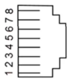 |
8 | TTDI | TDI | TDI | MOSI | 1 | |||||||
| 7 | TVPP | MCLR/Vpp | MCLR | RESET | RESET 3 | 2 | 1 | ||||||
| 6 | TVDD | VDD | VDD or VDDIO | VDD | VTG | VTG | VTG | VTG | VTG | VTG | 3 | 2 | |
| 5 | GND | GND | GND | GND | GND | GND | GND | GND | GND | GND | 4 | 3 | |
| 4 | PGD | DAT | TDO | SWO2 | TDO | DAT3 | DAT | MISO | DAT | 5 | 4 | ||
| 3 | PGC | CLK | TCK | SWCLK | TCK | SCK | CLK | 6 | 5 | ||||
| 2 | TAUX | RESET | RESET/dW | CLK | RESET | RESET | 7 | 6 | |||||
| 1 | TTMS | TMS | SWDIO 2 | TMS | 8 | ||||||||
- Black (8-pin) cable must be used for EJTAG, JAG, SWD, and ISP.
- SWO is used for trace. SWDIO is for debug.
- Pin may be used for High-Voltage Pulse reactivation of UPDI function depending on device. See device data sheet for details.
- These are example target connectors that are assumed similar to the debug unit (modular).
Pinouts for Data Stream Interfaces
| MPLAB® ICD 5 | DATA STREAM | Target2 | ||
| 8-Pin Modular Connector | PIC® and AVR® Devices | SAM Devices1 | 8-Pin Modular Connector | 6-Pin Modular Connector |
| Pin # | DGI UART/CDC | DGI UART/CDC | Pin # | Pin # |
| 8 | TX (target) | TX (target) | 1 | |
| 7 | 2 | 1 | ||
| 6 | VTG | VTG | 3 | 2 |
| 5 | GND | GND | 4 | 3 |
| 4 | 5 | 4 | ||
| 3 | 6 | 5 | ||
| 2 | RX (target) | 7 | 6 | |
| 1 | RX (target) | 8 | ||
- RX and TX pins moved because of wiring for other devices.
- These are example target connectors that are assumed similar to the debug unit (SIL).
Create, Build and Run Project
![]() Execute your code in Debug mode
Execute your code in Debug mode
![]() Execute your code in Non-Debug (release) mode
Execute your code in Non-Debug (release) mode
![]() Hold a device in Reset after programming
Hold a device in Reset after programming
Recommended Settings
| Component | Setting |
| Oscillator | OSC bits set properly running |
| Power | External supply connected |
| WDT | Disabled (device dependent) |
| Code-Protect | Disabled |
| Table Read | Protect Disabled |
| LVP | Disabled |
| BOD | Vdd > BOD VDD min. |
| AVdd and AVss | Must be connected, if applicable |
| PGCx/PGDx | Proper channel selected, if applicable |
| Programming | VDD voltage levels meet programming spec |
Note: See MPLAB IDE 5 In-Circuit Debugger online help for more information.
Reserved Resources
For information on reserved resources used by the debugger, see the MPLAB X IDE Help>Release Notes>Reserved Resources.
The Microchip name and logo, the Microchip logo, MPLAB and PIC are registered trademarks and PICkit is a trademark of Microchip Technology Incorporated in the U.S.A. and other countries. Arm and Cortex are registered trademarks of Arm Limited in the EU and other countries. All other trademarks mentioned herein are property of their respective companies.
© 2024, Microchip Technology Incorporated. All Rights Reserved. 3/24


Documents / Resources
 |
MICROCHIP MPLAB ICD 5 In Circuit Debugger [pdf] User Guide MPLAB ICD 5 In Circuit Debugger, MPLAB ICD, 5 In Circuit Debugger, Circuit Debugger, Debugger |