![]() PolarFire Family FPGA Custom Flow User Guide
PolarFire Family FPGA Custom Flow User Guide
Libero SoC v2024.2
Introduction (Ask a Question)
Libero System-on-Chip (SoC) software provides a fully integrated Field Programmable Gate Array (FPGA) design environment. However, a few users might want to use third-party synthesis and simulation tools outside the Libero SoC environment. Libero can now be integrated into the FPGA design environment. It is recommended to use Libero SoC to manage the entire FPGA design flow.
This user guide describes the Custom Flow for PolarFire and PolarFire SoC Family devices, a process to integrate Libero as a part of the larger FPGA design flow. Supported Device Families® The following table lists the device families that Libero SoC supports. However, some information in this guide might only apply to a specific family of devices. In this case, such information is clearly identified.
Table 1. Device Families Supported by Libero SoC
| Device Family | Description |
| PolarFire® | PolarFire FPGAs deliver the industry’s lowest power at mid-range densities with exceptional security and reliability. |
| PolarFire SoC | PolarFire SoC is the first SoC FPGA with a deterministic, coherent RISC-V CPU cluster, and a deterministic L2 memory subsystem enabling Linux® and real-time applications. |
Overview (Ask a Question)
While Libero SoC provides a fully integrated end-to-end design environment to develop SoC and FPGA designs, it also provides the flexibility to run synthesis and simulation with third-party tools outside the Libero SoC environment. However, some design steps must remain within the Libero SoC environment.
The following table lists the major steps in the FPGA design flow and indicates the steps for which Libero SoC must be used.
Table 1-1. FPGA Design Flow
| Design Flow Step | Must Use Libero | Description |
| Design Entry: HDL | No | Use third-party HDL editor/checker tool outside Libero® SoC if desired. |
| Design Entry: Configurators | Yes | Create first Libero project for IP catalog core component generation. |
| Automatic PDC/SDC constraint generation | No | Derived constraints need all HDL files and a derive_constraints utility when performed outside of Libero SoC, as described in Appendix C—Derive Constraints. |
| Simulation | No | Use third-party tool outside Libero SoC, if desired. Requires download of pre-compiled simulation libraries for target device, target simulator, and target Libero version used for backend implementation. |
| Synthesis | No | Use third-party tool outside Libero SoC if desired. |
| Design Implementation: Manage Constraints, Compile Netlist, Place-and- Route (see Overview) | Yes | Create second Libero project for the backend implementation. |
| Timing and Power Verification | Yes | Stay in second Libero project. |
| Configure Design Initialization Data and Memories | Yes | Use this tool to manage different types of memories and design initialization in the device. Stay in second project. |
| Programming File Generation | Yes | Stay in second project. |
![]() Important: You must download precompiled libraries available at the PreCompiled Simulation Libraries page to use a third-party simulator.
Important: You must download precompiled libraries available at the PreCompiled Simulation Libraries page to use a third-party simulator.
In a pure Fabric FPGA flow, enter your design using HDL or schematic entry and pass that directly
to the synthesis tools. The flow is still supported. PolarFire and PolarFire SoC FPGAs have significant
proprietary hard IP blocks requiring the use of configuration cores (SgCores) from the Libero SoC IP
catalog. Special handling is required for any blocks that comprise SoC functionality:
- PolarFire
– PF_UPROM
– PF_SYSTEM_SERVICES
– PF_CCC
– PF CLK DIV
– PF_CRYPTO
– PF_DRI
– PF_INIT_MONITOR
– PF_NGMUX
– PF_OSC
– RAMs (TPSRAM, DPSRAM, URAM)
– PF_SRAM_AHBL_AXI
– PF_XCVR_ERM
– PF_XCVR_REF_CLK
– PF_TX_PLL
– PF_PCIE
– PF_IO
– PF_IOD_CDR
– PF_IOD_CDR_CCC
– PF_IOD_GENERIC_RX
– PF_IOD_GENERIC_TX
– PF_IOD_GENERIC_TX_CCC
– PF_RGMII_TO_GMII
– PF_IOD_OCTAL_DDR
– PF_DDR3
– PF_DDR4
– PF_LPDDR3
– PF_QDR
– PF_CORESMARTBERT
– PF_TAMPER
– PF_TVS, and so on.
In addition to the preceding listed SgCores, there are many DirectCore soft IPs available for PolarFire and PolarFire SoC device families in the Libero SoC Catalog that use the FPGA fabric resources.
For design entry, if you use any one of the preceding components, you must use Libero SoC for part of the design entry (Component Configuration), but you can continue the rest of your Design Entry (HDL entry, and so on) outside of Libero. To manage the FPGA design flow outside of Libero, follow the steps provided in the rest of this guide.
1.1 Component Life Cycle (Ask a Question)
The following steps describe the life cycle of an SoC component and provide instructions on how to handle the data.
- Generate the component using its configurator in Libero SoC. This generates the following types of data:
– HDL files
– Memory files
– Stimulus and Simulation files
– Component SDC file - For HDL files, instantiate and integrate them in the rest of the HDL design using the external design entry tool/process.
- Supply memory files and stimulus files to your simulation tool.
- Supply Component SDC file to Derive Constraint tool for Constraint Generation. See Appendix C—Derive Constraints for more details.
- You must create a second Libero project, where you import the post-Synthesis netlist and your component metadata, thus completing the connection between what you generated and what you program.
1.2 Libero SoC Project Creation (Ask a Question)
Some design steps must be run inside the Libero SoC environment (Table 1-1). For these steps to run, you must create two Libero SoC projects. The first project is used for design component configuration and generation, and the second project is for the physical implementation of the top-level design.
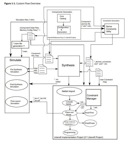
1.3 Custom Flow (Ask a Question)
The following figure shows:
- Libero SoC can be integrated as a part of the larger FPGA design flow with the third-party synthesis and simulation tools outside the Libero SoC environment.
- Various steps involved in the flow, starting from design creation and stitching all the way to programming the device.
- The data exchange (inputs and outputs) that must occur at each design flow step.
![]() Tip:
Tip:
- SNVM.cfg, UPROM.cfg
- *.mem file generation for Simulation: pa4rtupromgen.exe takes UPROM.cfg as input and generates UPROM.mem.
The following are the steps in the custom flow:
- Component configuration and generation:
a. Create a first Libero project (to serve as a Reference Project).
b. Select the Core from the Catalog. Double click the core to give it a component name and configure the component.
This automatically exports component data and files. A Component Manifests is also generated. See Component Manifests for details. For more details, see Component Configuration. - Complete your RTL design outside of Libero:
a. Instantiate the component HDL files.
b. The location of the HDL files is listed in the Component Manifests files. - Generate SDC constraints for the components. Use Derive Constraints utility to generate the timing constraint file(SDC) based on:
a. Component HDL files
b. Component SDC files
c. User HDL files
For more details, see Appendix C—Derive Constraints. - Synthesis tool/simulation tool:
a. Get HDL files, stimulus files, and component data from the specific locations as noted in the Component Manifests.
b. Synthesize and simulate the design with third-party tools outside Libero SoC. - Create your second (Implementation) Libero Project.
- Remove synthesis from the design flow tool chain (Project > Project Settings > Design Flow > clear the Enable Synthesis check box).
- Import the design source files (post-synthesis *.vm netlist from synthesis tool):
– Import post-synthesis *.vm netlist (File>Import> Synthesized Verilog Netlist (VM)).
– Component metadata *.cfg files for uPROM and/or sNVM. - Import any Libero SoC block component files. The block files must be in the *.cxz file format.
For more information on how to create a block, see PolarFire Block Flow User Guide. - Import the design constraints:
– Import I/O constraint files (Constraints Manager > I/OAttributes > Import).
– Import floorplanning *.pdc files (Constraints Manager > Floor Planner > Import).
– Import *.sdc timing constraint files (Constraints Manager > Timing >Import). Import the SDC file generated through Derive Constraint tool.
– Import *.ndc constraint files (Constraints Manager > NetlistAttributes > Import), if any. - Constraint file and tool association
– In the Constraint Manager, associate the *.pdc files to place and route, the *.sdc files to place and route and timing verifications, and the *.ndc files to Compile Netlist. - Complete design implementation
– Place and route, verify timing and power, configure design initialization data and memories, and programming file generation. - Validate the design
– Validate the design on FPGA and debug as necessary using the design tools provided with the Libero SoC design suite.
Component Configuration (Ask a Question)
The first step in the custom flow is to configure your components using a Libero reference project (also called first Libero project in Table 1-1). In subsequent steps, you use data from this reference project.
If you are using any components listed earlier, under the Overview in your design, perform the steps described in this section.
If you are not using any of the above components, you can write your RTL outside of Libero and directly import it into your Synthesis and Simulation tools. You can then proceed to the post-synthesis section and only import your post-synthesis *.vm netlist into your final Libero implementation project (also called second Libero project in Table 1-1).
2.1 Component Configuration Using Libero (Ask a Question)
After selecting the components that must be used from the preceding list, perform the following steps:
- Create a new Libero project (Core Configuration and Generation): Select the Device and Family that you target your final design to.
- Use one or more of the cores mentioned in Custom Flow.
a. Create a SmartDesign and configure the desired core and instantiate it in the SmartDesign component.
b. Promote all the pins to top level.
c. Generate the SmartDesign.
d. Double click the Simulate tool (any of Pre-Synthesis or Post-Synthesis or Post-Layout options) to invoke the simulator. You can exit the simulator after it is invoked. This step generates the simulation files necessary for your project.
![]() Tip: You must perform this step if you want to simulate your design outside Libero.
Tip: You must perform this step if you want to simulate your design outside Libero.
For more information, see Simulating Your Design.
e. Save your project—this is your reference project.
2.2 Component Manifests (Ask a Question)
When you generate your components, a set of files is generated for each component. The Component Manifest report details the set of files generated and used in each subsequent step (Synthesis, Simulation, Firmware Generation, and so on). This report gives you the locations of all the generated files needed to proceed with the Custom Flow. You can access the component manifest in the Reports area: Click Design > Reports to open the Reports tab. In the Reports tab, you see a set of manifest.txt files (Overview), one for each component you generated.
Tip: You must set a component or module as ‘”root”‘ to see the component manifest file contents in the Reports tab.
Alternatively, you can access the individual manifest report files for each core component generated or SmartDesign component from <project>/component/work/<component name>/<instance name>/<component name>_manifest.txt or <project>/component/work/<SmartDesign name>/<SmartDesign name>_manifest.txt. You can also access the manifest file contents of each component generated from the new Components tab in Libero, where the file locations are mentioned with respect to the project directory. Focus on the following Component Manifest reports:
- If you instantiated cores into a SmartDesign, read the file <smartdesign_name>_manifest.txt.
- If you created components for cores, read the <core_component_name>_manifest.txt.
You must use all Component Manifests reports that apply to your design. For example, if your project has a SmartDesign with one or more core components instantiated in it and you intend to use them all in your final design, then you must select files listed in the Component Manifests reports of all those components for use in your design flow.
2.3 Interpreting Manifest Files (Ask a Question)
When you open a component manifest file, you see paths to files in your Libero project and pointers on where in the design flow to use them. You might see the following types of files in a manifest file:
- HDL source files for all Synthesis and Simulation tools
- Stimulus files for all Simulation tools
- Constraint files
Following is the Component Manifest of a PolarFire core component. Each type of file is necessary downstream in your design flow. The following sections describe integration of the files from the manifest into your design flow.
Constraint Generation (Ask a Question)
When performing configuration and generation, ensure to write/generate the SDC/PDC/NDC constraint files for the design to pass them to Synthesis, Place-and-Route, and Verify Timing tools.
Use the Derive Constraints utility outside of the Libero environment to generate constraints instead of writing them manually. To use the Derive Constraint utility outside of the Libero environment, you must:
- Supply user HDL, component HDL, and component SDC constraint files
- Specify the top level module
- Specify the location where to generate the derived constraint files
The SDC component constraints are available under <project>/component/work/<component name>/<instance_name>/ directory after component configuration and generation.
For more details on how to generate constraints for your design, see Appendix C—Derive Constraints.
Synthesizing Your Design (Ask a Question)
One of the primary features of the Custom Flow is to allow you to use a third-party synthesis
tool outside Libero. The custom flow supports the use of Synopsys SynplifyPro. To synthesize your
project, use the following procedure:
- Create a new project in your Synthesis tool, targeting the same device family, die, and package as the Libero project you created.
a. Import your own RTL files as you normally do.
b. Set the Synthesis output to be Structural Verilog (.vm).
Tip: Structural Verilog (.vm) is the only supported synthesis output format in PolarFire. - Import Component HDL files into your Synthesis project:
a. For each Component Manifests Report: For each file under HDL source files for all Synthesis and Simulation tools, import the file into your Synthesis Project. - Import the file polarfire_syn_comps.v (if using Synopsys Synplify) from <Libero
Installation location>/data/aPA5M to your Synthesis project. - Import the previously generated SDC file through the Derived Constraint tool (see Appendix
A—Sample SDC Constraints) into the Synthesis tool. This constraint file constrains the synthesis tool to achieve timing closure with less effort and fewer design iterations.
![]() Important:
Important:
- If you plan to use the same *.sdc file to constrain Place-and-Route during the design implementation phase, you must import this *.sdc into the synthesis project. This is to ensure that there are no design object name mismatches in the synthesized netlist and the Place-and-Route constraints during the implementation phase of the design process. If you do not include this *.sdc file in the Synthesis step, the netlist generated from Synthesis may fail the Place and Route step because of design object name mismatches.
a. Import Netlist Attributes *.ndc, if any, into the Synthesis tool.
b. Run Synthesis. - The location of your Synthesis tool output has the *.vm netlist file generated post Synthesis. You must import the netlist into the Libero Implementation Project to continue with the design process.
Simulating Your Design (Ask a Question)
To simulate your design outside of Libero (that is, using your own simulation environment and simulator), perform the following steps:
- Design Files:
a. Pre-Synthesis simulation:
• Import your RTL into your simulation project.
• For each Component Manifests Report.
– Import each file under HDL source files for all Synthesis and Simulation tools into your simulation project.
• Compile these files as per your simulator’s instructions.
b. Post-synthesis simulation:
• Import your post-synthesis *.vm netlist (generated in Synthesizing Your Design) into your simulation project and compile it.
c. Post-layout simulation:
• First, complete implementing your design (see Implementing Your Design). Ensure that your final Libero project is in post-layout state.
• Double-click Generate BackAnnotated Files in the Libero Design Flow window. It generates two files:
<project directory>/designer/<root>/<root>_ba.v/vhd <project directory>/designer/
<root>/<root>_ba.sdf
• Import both of these files into your simulation tool. - Stimulus and Configuration files:
a. For each Component Manifests Report:
• Copy all files under the Stimulus Files for all Simulation Tools sections to the root directory of your Simulation project.
b. Ensure that any Tcl files in the preceding lists (in step 2.a) are executed first, before the start of simulation.
c. UPROM.mem: If you use the UPROM core in your design with the option Use content for simulation enabled for one or more data storage clients that you wish to simulate, you must use the executable pa4rtupromgen (pa4rtupromgen.exe on windows) to generate the UPROM.mem file. The pa4rtupromgen executable takes the UPROM.cfg file as inputs through a Tcl script file and outputs the UPROM.mem file required for simulations. This UPROM.mem file must be copied to the simulation folder prior to the simulation run. An example showing the pa4rtupromgen executable usage is provided in the following steps. The UPROM.cfg file is available in the directory <Project>/component/work/<uPROM component name>/ <uPROM instance name> in the Libero project that you used to generate the UPROM component.
d. snvm.mem: If you use the System Services core in your design and configured the sNVM tab in the core with the option Use content for simulation enabled for one or more clients that you wish to simulate, a snvm.mem file is automatically generated to
the directory <Project>/component/work/<PolarFire System Services component name>/<uPROM instance name> in the Libero project that you used to generate the System Services component. This snvm.mem file must be copied to the simulation folder prior to the simulation run. - Create a working folder and a sub-folder named simulation under the working folder.
The pa4rtupromgen executable expect the presence of the simulation sub folder in the working folder and the *.tcl script is placed in the simulation sub folder. - Copy the UPROM.cfg file from the first Libero project created for component generation into the working folder.
- Paste the following commands in a *.tcl script and place it in the simulation folder created in step 3.
Sample *.tcl for PolarFire and PolarFire Soc Family devices to generate URPOM.mem file
from UPROM.cfg
set_device -fam <family> -die <internal_die_name> -pkg <internal_pkg_name>
set_input_cfg -path <path_to_UPROM.cfg>
set_sim_mem -path <path_to_UPROM_Initialization_File/UPROM.mem>
gen_sim -use_init false
For the proper internal name to use for the die and package, see the *.prjx file of the first Libero project (used for component generation).
The argument use_init must be set to false.
Use the set_sim_mem command to specify the path to the output file UPROM.mem that is
generated upon execution of the script file with the pa4rtupromgen executable. - At the command prompt or cygwin terminal, go to the working directory created in step 3.
Execute the pa4rtupromgen command with the–script option and pass to it the *.tcl script created in the previous step.
For Windows
<Libero_SoC_release_installation>/designer/bin/pa4rtupromgen.exe \
–script./simulation/<Tcl_script_name>.tcl
For Linux:
<Libero_SoC_release_installation>/bin/pa4rtupromgen
–script./simulation/<tcl_script_name>.tcl - After successful execution of the pa4rtupromgen executable, check that the UPROM.mem file is generated in the location specified in the set_sim_mem command in the *.tcl script.
- To simulate the sNVM, copy the snvm.mem file from your first Libero project (used for component configuration) into the top level simulation folder of your simulation project to run simulation (outside of Libero SoC). To simulate UPROM contents, copy the generated UPROM.mem file into the top level simulation folder of your simulation project to run simulation (outside of Libero SoC).
![]() Important: To simulate the functionality of SoC Components, download the precompiled PolarFire simulation libraries and import them into your simulation environment as described here. For more details, see Appendix B—Importing Simulation Libraries into Simulation Environment.
Important: To simulate the functionality of SoC Components, download the precompiled PolarFire simulation libraries and import them into your simulation environment as described here. For more details, see Appendix B—Importing Simulation Libraries into Simulation Environment.
Implementing Your Design (Ask a Question)
After completing the Synthesis and Post-Synthesis simulation in your environment, you must use Libero again to physically implement your design, run timing and power analysis, and generate your programming file.
- Create a new Libero project for the physical implementation and layout of the design. Ensure to target the same device as in the reference project you created in Component Configuration.
- After project creation, remove Synthesis from the tool chain in the Design Flow window (Project > Project Settings > Design Flow > Uncheck Enable Synthesis).
- Import your post-synthesis *.vm file into this project, (File > Import > Synthesized Verilog Netlist (VM)).
 Tip: It is recommended that you create a link to this file, so that if you resynthesize your design, Libero always uses the latest post-synthesis netlist.
a. In the Design Hierarchy window, note the name of the root module.
- Import the constraints into the Libero project. Use the Constraint Manager to import *.pdc/*.sdc/*.ndc constraints.
a. Import I/O *.pdc constraint files (Constraints Manager > I/O Attributes >Import).
b. Import Floorplanning *.pdc constraint files (Constraints Manager > Floor Planner >Import).
c. Import *.sdc timing constraint files (Constraints Manager > Timing > Import). If your design has any of the cores listed in Overview, ensure to import the SDC file generated through derive constraint tool.
d. Import *.ndc constraint files (Constraints Manager > Netlist Attributes > Import). - Associate Constraints Files to design tools.
a. Open Constraint Manager (Manage Constraints > Open Manage Constraints View).
Check the Place-and-Route and Timing Verification check box next to the constraint file to establish constraint file and tool association. Associate the *.pdc constraint to Place-andRoute and the *.sdc to both Place-and-Route and Timing Verification. Associate the *.ndc file to Compile Netlist.
Tip: If Place and Route fails with this *.sdc constraint file, then import this same *.sdc file to synthesis and re-run synthesis. - Click Compile Netlist and then Place and Route to complete the layout step.
- The Configure Design Initialization Data and Memories tool allows you to initialize design blocks, such as LSRAM, µSRAM, XCVR (transceivers), and PCIe using data stored in nonvolatile µPROM, sNVM, or external SPI Flash storage memory. The tool has the following tabs for defining the specification of the design initialization sequence, the specification of the initialization clients, user data clients.
– Design Initialization tab
– µPROM tab
– sNVM tab
– SPI Flash tab
– Fabric RAMs tab
Use the tabs in the tool to configure the design initialization data and memories. After completing the configuration, perform the following steps to program the initialization data:
• Generate initialization clients
• Generate or export the bitstream
• Program the device
For detailed information on how to use this tool, see Libero SoC Design Flow User Guide. For more information on the Tcl commands used to configure various tabs in the tool and specify memory configuration files (*.cfg), see Tcl Commands Reference Guide. - Generate a Programming File from this project and use it to program your FPGA.
Appendix A—Sample SDC Constraints (Ask a Question
Libero SoC generates SDC timing constraints for certain IP cores, such as CCC, OSC, Transceiver and so on. Passing the SDC constraints to design tools increases the chance of meeting timing closure with less effort and fewer design iterations. The full hierarchical path from the top-level instance is given for all design objects referenced in the constraints.
7.1 SDC Timing Constraints (Ask a Question)
In the Libero IP core reference project, this top-level SDC constraint file is available from the Constraint Manager (Design Flow > Open Manage Constraint View >Timing > Derive Constraints).
![]() Important: See this file to set the SDC constraints if your design contains CCC, OSC, Transceiver, and other components. Modify the full hierarchical path, if necessary, to match your design hierarchy or use the Derive_Constraints utility and steps in Appendix C—Derive Constraints on the component level SDC file.
Important: See this file to set the SDC constraints if your design contains CCC, OSC, Transceiver, and other components. Modify the full hierarchical path, if necessary, to match your design hierarchy or use the Derive_Constraints utility and steps in Appendix C—Derive Constraints on the component level SDC file.
Save the file to a different name and import the SDC file to the synthesis tool, Place-and-Route Tool, and Timing Verifications, just like any other SDC constraint files.
7.1.1 Derived SDC File (Ask a Question)
# This file was generated based on the following SDC source files:
# /drive/icicle_kit_ref_des/icicle-kit-reference-design-master/MPFS_ICICLE/component/work/
PF_CCC_C0/PF_CCC_C0_0/PF_CCC_C0_PF_CCC_C0_0_PF_CCC.sdc
# /drive/icicle_kit_ref_des/icicle-kit-reference-design-master/MPFS_ICICLE/component/work/
CLK_DIV/CLK_DIV_0/CLK_DIV_CLK_DIV_0_PF_CLK_DIV.sdc
# /drive/icicle_kit_ref_des/icicle-kit-reference-design-master/MPFS_ICICLE/component/work/
TRANSMIT_PLL/TRANSMIT_PLL_0/TRANSMIT_PLL_TRANSMIT_PLL_0_PF_TX_PLL.sdc
# /drive/icicle_kit_ref_des/icicle-kit-reference-design-master/MPFS_ICICLE/component/work/
DMA_INITIATOR/DMA_INITIATOR_0/DMA_INITIATOR.sdc
# /drive/icicle_kit_ref_des/icicle-kit-reference-design-master/MPFS_ICICLE/component/work/
FIC0_INITIATOR/FIC0_INITIATOR_0/FIC0_INITIATOR.sdc
# /drive/icicle_kit_ref_des/icicle-kit-reference-design-master/MPFS_ICICLE/component/work/
ICICLE_MSS/ICICLE_MSS.sdc
# /drive/icicle_kit_ref_des/icicle-kit-reference-design-master/MPFS_ICICLE/component/work/
PF_PCIE_C0/PF_PCIE_C0_0/PF_PCIE_C0_PF_PCIE_C0_0_PF_PCIE.sdc
# /drive/icicle_kit_ref_des/icicle-kit-reference-design-master/MPFS_ICICLE/component/work/
PCIE_INITIATOR/PCIE_INITIATOR_0/PCIE_INITIATOR.sdc
# /drive/aPA5M/cores/constraints/osc_rc160mhz.sdc
# *** Any modifications to this file will be lost if derived constraints is re-run. ***
create_clock -name {CLOCKS_AND_RESETS_inst_0/OSCILLATOR_160MHz_inst_0/OSCILLATOR_160MHz_0/
I_OSC_160/CLK} -period 6.25
[ get_pins { CLOCKS_AND_RESETS_inst_0/OSCILLATOR_160MHz_inst_0/OSCILLATOR_160MHz_0/
I_OSC_160/CLK } ]
create_clock -name {REF_CLK_PAD_P} -period 10 [ get_ports { REF_CLK_PAD_P } ]
create_clock -name {CLOCKS_AND_RESETS_inst_0/TRANSMIT_PLL_0/TRANSMIT_PLL_0/txpll_isnt_0/
DIV_CLK} -period 8
[ get_pins { CLOCKS_AND_RESETS_inst_0/TRANSMIT_PLL_0/TRANSMIT_PLL_0/txpll_isnt_0/DIV_CLK } ]
create_generated_clock -name {CLOCKS_AND_RESETS_inst_0/CCC_FIC_x_CLK/PF_CCC_C0_0/pll_inst_0/
OUT0} -multiply_by 25 -divide_by 32 -source
[ get_pins { CLOCKS_AND_RESETS_inst_0/CCC_FIC_x_CLK/PF_CCC_C0_0/pll_inst_0/REF_CLK_0 } ]
-phase 0
[ get_pins { CLOCKS_AND_RESETS_inst_0/CCC_FIC_x_CLK/PF_CCC_C0_0/pll_inst_0/OUT0 } ]
create_generated_clock -name {CLOCKS_AND_RESETS_inst_0/CCC_FIC_x_CLK/PF_CCC_C0_0/pll_inst_0/
OUT1} -multiply_by 25 -divide_by 32 -source
[ get_pins { CLOCKS_AND_RESETS_inst_0/CCC_FIC_x_CLK/PF_CCC_C0_0/pll_inst_0/REF_CLK_0 } ]
-phase 0
[ get_pins { CLOCKS_AND_RESETS_inst_0/CCC_FIC_x_CLK/PF_CCC_C0_0/pll_inst_0/OUT1 } ]
create_generated_clock -name {CLOCKS_AND_RESETS_inst_0/CCC_FIC_x_CLK/PF_CCC_C0_0/pll_inst_0/
OUT2} -multiply_by 25 -divide_by 32 -source
[ get_pins { CLOCKS_AND_RESETS_inst_0/CCC_FIC_x_CLK/PF_CCC_C0_0/pll_inst_0/REF_CLK_0 } ]
-phase 0
[ get_pins { CLOCKS_AND_RESETS_inst_0/CCC_FIC_x_CLK/PF_CCC_C0_0/pll_inst_0/OUT2 } ]
create_generated_clock -name {CLOCKS_AND_RESETS_inst_0/CCC_FIC_x_CLK/PF_CCC_C0_0/pll_inst_0/
OUT3} -multiply_by 25 -divide_by 64 -source
[ get_pins { CLOCKS_AND_RESETS_inst_0/CCC_FIC_x_CLK/PF_CCC_C0_0/pll_inst_0/REF_CLK_0 } ]
-phase 0
[ get_pins { CLOCKS_AND_RESETS_inst_0/CCC_FIC_x_CLK/PF_CCC_C0_0/pll_inst_0/OUT3 } ]
create_generated_clock -name {CLOCKS_AND_RESETS_inst_0/CLK_160MHz_to_CLK_80MHz/CLK_DIV_0/I_CD/
Y_DIV} -divide_by 2 -source
[ get_pins { CLOCKS_AND_RESETS_inst_0/CLK_160MHz_to_CLK_80MHz/CLK_DIV_0/I_CD/A } ]
[ get_pins { CLOCKS_AND_RESETS_inst_0/CLK_160MHz_to_CLK_80MHz/CLK_DIV_0/I_CD/Y_DIV } ]
set_false_path -through [ get_nets { DMA_INITIATOR_inst_0/ARESETN* } ]
set_false_path -from [ get_cells { DMA_INITIATOR_inst_0/*/SlvConvertor_loop[*].slvcnv/slvCDC/
genblk1*/rdGrayCounter*/cntGray* } ]
-to [ get_cells { DMA_INITIATOR_inst_0/*/SlvConvertor_loop[*].slvcnv/slvCDC/genblk1*/
rdPtr_s1* } ]
set_false_path -from [ get_cells { DMA_INITIATOR_inst_0/*/SlvConvertor_loop[*].slvcnv/slvCDC/
genblk1*/wrGrayCounter*/cntGray* } ]
-to [ get_cells { DMA_INITIATOR_inst_0/*/SlvConvertor_loop[*].slvcnv/slvCDC/genblk1*/
wrPtr_s1* } ]
set_false_path -through [ get_nets { FIC0_INITIATOR_inst_0/ARESETN* } ]
set_false_path -to [ get_pins { PCIE/PF_PCIE_C0_0/PCIE_1/INTERRUPT[0] PCIE/PF_PCIE_C0_0/
PCIE_1/INTERRUPT[1] PCIE/PF_PCIE_C0_0/PCIE_1/INTERRUPT[2] PCIE/PF_PCIE_C0_0/PCIE_1/
INTERRUPT[3] PCIE/PF_PCIE_C0_0/PCIE_1/INTERRUPT[4] PCIE/PF_PCIE_C0_0/PCIE_1/INTERRUPT[5]
PCIE/PF_PCIE_C0_0/PCIE_1/INTERRUPT[6] PCIE/PF_PCIE_C0_0/PCIE_1/INTERRUPT[7] PCIE/PF_PCIE_C0_0/
PCIE_1/WAKEREQ PCIE/PF_PCIE_C0_0/PCIE_1/MPERST_N } ]
set_false_path -from [ get_pins { PCIE/PF_PCIE_C0_0/PCIE_1/TL_CLK } ]
set_false_path -through [ get_nets { PCIE_INITIATOR_inst_0/ARESETN* } ]
Appendix B—Importing Simulation Libraries into Simulation Environment (Ask a Question)
The default simulator for RTL simulation with Libero SoC is ModelSim ME Pro.
Pre-compiled libraries for default simulator are available with Libero installation at directory<install_location>/Designer/lib/modelsimpro/precompiled/vlog for® supported families. Libero SoC also supports other third-party simulators editions of ModelSim, Questasim, VCS, Xcelium
, Active HDL, and Riviera Pro. Download respective pre-compiled libraries from Libero SoC v12.0 and later based on the simulator and its version.
Similar to Libero environment, run.do file must be created to run simulation outside Libero.
Create a simple run.do file that has commands to establish library for compilation results, library mapping, compilation, and simulation. Follow the steps to create a basic run.do file.
- Create a logical library to store compilation results using vlib command vlib presynth.
- Map the logical library name to pre-compiled library directory using vmap command vmap <logical_name> <pre-compiled directory path>.
- Compile source files—use language-specific compiler commands to compile design files into working directory.
– vlog for .v/.sv
– vcom for .vhd - Load the design for simulation using vsim command by specifying name of any top-level module.
- Simulate the design using run command.
After loading the design, simulation time is set to zero, and you can enter the run command to begin simulation.
In the simulator transcript window, execute run.do file as run.do run the simulation. Sample run.do file as follows.
quietly set ACTELLIBNAME PolarFire quietly set PROJECT_DIR “W:/Test/basic_test” if
{[file exists presynth/_info]} { echo “INFO: Simulation library presynth exists” } else
{ file delete -force presynth vlib presynth } vmap presynth presynth vmap PolarFire
“X:/Libero/Designer/lib/modelsimpro/precompiled/vlog/PolarFire” vlog -sv -work presynth
“${PROJECT_DIR}/hdl/top.v” vlog “+incdir+${PROJECT_DIR}/stimulus” -sv -work presynth “$
{PROJECT_DIR}/stimulus/tb.v” vsim -L PolarFire -L presynth -t 1ps presynth.tb add wave /tb/*
run 1000ns log /tb/* exit
Appendix C—Derive Constraints (Ask a Question)
This appendix describes the Derive Constraints Tcl commands.
9.1 Derive Constraints Tcl Commands (Ask a Question)
The derive_constraints utility helps you derive constraints from the RTL or the configurator outside the Libero SoC design environment. To generate constraints for your design, you need the User HDL, Component HDL, and Component Constraints files. The SDC component constraints files are available under <project>/component/work/<component name>/<instance_name>/ directory after component configuration and generation.
Each component constraint file consists of the set_component tcl command (specifies the component name) and the list of constraints generated after configuration. The constraints are generated based on the configuration and are specific to each component.
Example 9-1. Component Constraint File for the PF_CCC Core
Here is an example of a component constraint file for the PF_CCC core:
set_component PF_CCC_C0_PF_CCC_C0_0_PF_CCC
# Microchip Corp.
# Date: 2021-Oct-26 04:36:00
# Base clock for PLL #0
create_clock -period 10 [ get_pins { pll_inst_0/REF_CLK_0 } ]
create_generated_clock -divide_by 1 -source [ get_pins { pll_inst_0/
REF_CLK_0 } ]
-phase 0 [ get_pins { pll_inst_0/OUT0 } ]
Here, create_clock and create_generated_clock are reference and output clock constraints respectively, which are generated based on the configuration.
9.1.1 Working with derive_constraints Utility (Ask a Question)
Derive constraints traverse through the design and allocate new constraints for each instance of component based on previously provided component SDC files. For the CCC reference clocks, it propagates back through the design to find the source of the reference clock. If the source is an I/O, the reference clock constraint will be set on the I/O. If it is a CCC output or another clock source (for example, Transceiver, oscillator), it uses the clock from the other component and reports a warning if the intervals do not match. Derive constraints will also allocate constraints for some macros like on-chip oscillators if you have them in your RTL.
To execute the derive_constraints utility, you must supply a .tcl file command-line argument with the following information in the specified order.
- Specify device information using the information in section set_device.
- Specify path to the RTL files using the information in section read_verilog or read_vhdl.
- Set top level module using the information in section set_top_level.
- Specify path to the component SDC files using the information in section read_sdc or read_ndc.
- Execute the files using the information in section derive_constraints.
- Specify path to the SDC derived constraints file using the information in section write_sdc or write_pdc or write_ndc.
Example 9-2. Execution and Contents of the derive.tcl File
The following is an example command-line argument to execute the derive_constraints utility.
$ <libero_installation_path>/bin{64}/derive_constraints derive.tcl
The contents of the derive.tcl file:
# Device information
set_device -family PolarFire -die MPF100T -speed -1
# RTL files
read_verilog -mode system_verilog project/component/work/txpll0/
txpll0_txpll0_0_PF_TX_PLL.v
read_verilog -mode system_verilog {project/component/work/txpll0/txpll0.v}
read_verilog -mode system_verilog {project/component/work/xcvr0/I_XCVR/
xcvr0_I_XCVR_PF_XCVR.v}
read_verilog -mode system_verilog {project/component/work/xcvr0/xcvr0.v}
read_vhdl -mode vhdl_2008 {project/hdl/xcvr1.vhd}
#Component SDC files
set_top_level {xcvr1}
read_sdc -component {project/component/work/txpll0/txpll0_0/
txpll0_txpll0_0_PF_TX_PLL.sdc}
read_sdc -component {project/component/work/xcvr0/I_XCVR/
xcvr0_I_XCVR_PF_XCVR.sdc}
#Use derive_constraint command
derive_constraints
#SDC/PDC/NDC result files
write_sdc {project/constraint/xcvr1_derived_constraints.sdc}
write_pdc {project/constraint/fp/xcvr1_derived_constraints.pdc}
9.1.2 set_device (Ask a Question)
Description
Specify family name, die name, and speed grade.
set_device -family <family_name> -die <die_name> -speed <speed>
Arguments
| Parameter | Type | Description |
| -family <family_name> | String | Specify the family name. Possible values are PolarFire®, PolarFire SoC. |
| -die <die_name> | String | Specify the die name. |
| -speed <speed> | String | Specify the device speed grade. Possible values are STD or -1. |
| Return Type | Description |
| 0 | Command succeeded. |
| 1 | Command failed. There is an error. You can observe the error message in the console. |
List of Errors
| Error Code | Error Message | Description |
| ERR0023 | Required parameter—die is missing | The die option is mandatory and must be specified. |
| ERR0005 | Unknown die ‘MPF30’ | The value of -die option is not correct. See the possible list of values in option’s description. |
| ERR0023 | Parameter—die is missing value | The die option is specified without value. |
| ERR0023 | Required parameter—family is missing | The family option is mandatory and must be specified. |
| ERR0004 | Unknown family ‘PolarFire®’ | The family option is not correct. See the possible list of values in option’s description. |
| ………… continued | ||
| Error Code | Error Message | Description |
| ERR0023 | Parameter—family is missing value | The family option is specified without value. |
| ERR0023 | Required parameter—speed is missing | The speed option is mandatory and must be specified. |
| ERR0007 | Unknown speed ‘<speed>’ | The speed option is not correct. See the possible list of values in option’s description. |
| ERR0023 | Parameter—speed is missing value | The speed option is specified without value. |
Example
set_device -family {PolarFire} -die {MPF300T_ES} -speed -1
set_device -family SmartFusion 2 -die M2S090T -speed -1
9.1.3 read_verilog (Ask a Question)
Description
Read a Verilog file using Verific.
read_verilog [-lib <libname>] [-mode <mode>] <filename>
Arguments
| Parameter | Type | Description |
| -lib <libname> | String | Specify the library that contains the modules to be added into the library. |
| -mode <mode> | String | Specify the Verilog standard. Possible values are verilog_95, verilog_2k, system_verilog_2005, system_verilog_2009, system_verilog, verilog_ams, verilog_psl, system_verilog_mfcu. Values are case insensitive. Default is verilog_2k. |
| filename | String | Verilog file name. |
| Return Type | Description |
| 0 | Command succeeded. |
| 1 | Command failed. There is an error. You can observe the error message in the console. |
List of Errors
| Error Code | Error Message | Description |
| ERR0023 | Parameter—lib is missing value | The lib option is specified without value. |
| ERR0023 | Parameter—mode is missing value | The mode option is specified without value. |
| ERR0015 | Unknown mode ‘<mode>’ | The specified verilog mode is unknown. See the list of possible verilog mode in—mode option description. |
| ERR0023 | Required parameter file name is missing | No verilog file path is provided. |
| ERR0016 | Failed due to Verific’s parser | Syntax error in verilog file. Verific’s parser can be observed in the console above the error message. |
| ERR0012 | set_device is not called | The device information is not specified. Use set_device command to describe the device. |
Example
read_verilog -mode system_verilog {component/work/top/top.v}
read_verilog -mode system_verilog_mfcu design.v
9.1.4 read_vhdl (Ask a Question)
Description
Add a VHDL file into the list of VHDL files.
read_vhdl [-lib <libname>] [-mode <mode>] <filename>
Arguments
| Parameter | Type | Description |
| -lib <libname> | — | Specify the library in which the content must be added. |
| -mode <mode> | — | Specifies the VHDL standard. Default is VHDL_93. Possible values are vhdl_93, vhdl_87, vhdl_2k, vhdl_2008, vhdl_psl. Values are case insensitive. |
| filename | — | VHDL file name. |
| Return Type | Description |
| 0 | Command succeeded. |
| 1 | Command failed. There is an error. You can observe the error message in the console. |
List of Errors
| Error Code | Error Message | Description |
| ERR0023 | Parameter—lib is missing value | The lib option is specified without value. |
| ERR0023 | Parameter—mode is missing value | The mode option is specified without value. |
| ERR0018 | Unknown mode ‘<mode>’ | The specified VHDL mode is unknown. See the list of possible VHDL mode in—mode option description. |
| ERR0023 | Required parameter file name is missing | No VHDL file path is provided. |
| ERR0019 | Unable to register invalid_path.v file | The specified VHDL file does not exist or does not have read permissions. |
| ERR0012 | set_device is not called | The device information is not specified. Use set_device command to describe the device. |
Example
read_vhdl -mode vhdl_2008 osc2dfn.vhd
read_vhdl {hdl/top.vhd}
9.1.5 set_top_level (Ask a Question)
Description
Specify the name of the top-level module in RTL.
set_top_level [-lib <libname>] <name>
Arguments
| Parameter | Type | Description |
| -lib <libname> | String | The library to search for the top-level module or entity (Optional). |
| name | String | The top-level module or entity name. |
| Return Type | Description |
| 0 | Command succeeded. |
| 1 | Command failed. There is an error. You can observe the error message in the console. |
List of Errors
| Error Code | Error Message | Description |
| ERR0023 | Required parameter top level is missing | The top level option is mandatory and must be specified. |
| ERR0023 | Parameter—lib is missing value | The lib option is specified without values. |
| ERR0014 | Unable to find top level <top> in library <lib> | The specified top-level module is not defined in the provided library. To fix this error, the top module or library name must be corrected. |
| ERR0017 | Elaborate failed | Error in RTL elaboration process. The error message can be observed from the console. |
Example
set_top_level {top}
set_top_level -lib hdl top
9.1.6 read_sdc (Ask a Question)
Description
Read a SDC file into the component database.
read_sdc -component <filename>
Arguments
| Parameter | Type | Description |
| -component | — | This is a mandatory flag for read_sdc command when we derive constraints. |
| filename | String | Path to the SDC file. |
| Return Type | Description |
| 0 | Command succeeded. |
| 1 | Command failed. There is an error. You can observe the error message in the console. |
List of Errors
| Error Code | Error Message | Description |
| ERR0023 | Required parameter file name is missing. | The mandatory option file name is not specified. |
| ERR0000 | SDC file <file_path> is not readable. | The specified SDC file does not have read permissions. |
| ERR0001 | Unable to open <file_path> file. | The SDC file does not exist. The path must be corrected. |
| ERR0008 | Missing set_component command in <file_path> file | The specified component of SDC file does not specify the component. |
| Error Code | Error Message | Description |
| ERR0009 | <List of errors from sdc file> | The SDC file contains incorrect sdc commands. For example,
when there is an error in set_multicycle_path constraint: Error while executing command read_sdc: in <sdc_file_path> file: Error in command set_multicycle_path: Unknown parameter [get_cells {reg_a}]. |
Example
read_sdc -component {./component/work/ccc0/ccc0_0/ccc0_ccc0_0_PF_CCC.sdc}
9.1.7 read_ndc (Ask a Question)
Description
Read an NDC file into the component database.
read_ndc -component <filename>
Arguments
| Parameter | Type | Description |
| -component | — | This is a mandatory flag for read_ndc command when we derive constraints. |
| filename | String | Path to the NDC file. |
| Return Type | Description |
| 0 | Command succeeded. |
| 1 | Command failed. There is an error. You can observe the error message in the console. |
List of Errors
| Error Code | Error Message | Description |
| ERR0001 | Unable to open <file_path> file | The NDC file does not exist. The path must be corrected. |
| ERR0023 | Required parameter—AtclParamO_ is missing. | The mandatory option filename is not specified. |
| ERR0023 | Required parameter—component is missing. | Component option is mandatory and must be specified. |
| ERR0000 | NDC file ‘<file_path>’ is not readable. | The specified NDC file does not have read permissions. |
Example
read_ndc -component {component/work/ccc1/ccc1_0/ccc_comp.ndc}
9.1.8 derive_constraints (Ask a Question)
Description
Instantiate component SDC files into the design-level database.
derive_constraints
Arguments
| Return Type | Description |
| 0 | Command succeeded. |
| 1 | Command failed. There is an error. You can observe the error message in the console. |
List of Errors
| Error Code | Error Message | Description |
| ERR0013 | Top-level is not defined | This means that the top-level module or entity is not specified. To fix this call, issue the set_top_level command before the derive_constraints command. |
Example
derive_constraints
9.1.9 write_sdc (Ask a Question)
Description
Writes a constraint file in SDC format.
write_sdc <filename>
Arguments
| Parameter | Type | Description |
| <filename> | String | Path to the SDC file will be generated. This is a mandatory option. If the file exists, it will be overwritten. |
| Return Type | Description |
| 0 | Command succeeded. |
| 1 | Command failed. There is an error. You can observe the error message in the console. |
List of Errors
| Error Code | Error Message | Description |
| ERR0003 | Unable to open <file path> file. | File path is not correct. Check whether the parent directories exist. |
| ERR0002 | SDC file ‘<file path>’ is not writable. | The specified SDC file does not have write permission. |
| ERR0023 | Required parameter file name is missing. | The SDC file path is a mandatory option and must be specified. |
Example
write_sdc “derived.sdc”
9.1.10 write_pdc (Ask a Question)
Description
Writes physical constraints (Derive Constraints only).
write_pdc <filename>
Arguments
| Parameter | Type | Description |
| <filename> | String | Path to the PDC file will be generated. This is a mandatory option. If the file path exists, it will be overwritten. |
| Return Type | Description |
| 0 | Command succeeded. |
| 1 | Command failed. There is an error. You can observe the error message in the console. |
List of Errors
| Error Code | Error Messages | Description |
| ERR0003 | Unable to open <file path> file | The file path is not correct. Check whether the parent directories exist. |
| ERR0002 | PDC file ‘<file path>’ is not writeable. | The specified PDC file does not have write permission. |
| ERR0023 | Required parameter file name is missing | The PDC file path is a mandatory option and must be specified. |
Example
write_pdc “derived.pdc”
9.1.11 write_ndc (Ask a Question)
Description
Writes NDC constraints into a file.
write_ndc <filename>
Arguments
| Parameter | Type | Description |
| filename | String | Path to the NDC file will be generated. This is a mandatory option. If the file exists, it will be overwritten. |
| Return Type | Description |
| 0 | Command succeeded. |
| 1 | Command failed. There is an error. You can observe the error message in the console. |
List of Errors
| Error Code | Error Messages | Description |
| ERR0003 | Unable to open <file_path> file. | File path is not correct. The parent directories do not exist. |
| ERR0002 | NDC file ‘<file_path>’ is not writable. | The specified NDC file does not have write permission. |
| ERR0023 | Required parameter _AtclParamO_ is missing. | The NDC file path is a mandatory option and must be specified. |
Example
write_ndc “derived.ndc”
9.1.12 add_include_path (Ask a Question)
Description
Specifies a path to search include files when reading RTL files.
add_include_path <directory>
Arguments
| Parameter | Type | Description |
| directory | String | Specifies a path to search include files when reading RTL files. This option is mandatory. |
| Return Type | Description |
| 0 | Command succeeded. |
| Return Type | Description |
| 1 | Command failed. There is an error. You can observe the error message in the console. |
List of Errors
| Error Code | Error Message | Description |
| ERR0023 | Required parameter include path is missing. | The directory option is mandatory and must be provided. |
Note: If the directory path is not correct, then add_include_path will be passed without an error.
However, read_verilog/read_vhd commands will fail due to Verific’s parser.
Example
add_include_path component/work/COREABC0/COREABC0_0/rtl/vlog/core
Revision History (Ask a Question)
The revision history describes the changes that were implemented in the document. The changes are listed by revision, starting with the most current publication.
| Revision | Date | Description |
| F | 08/2024 | The following changes are made in this revision: • Updated section Appendix B—Importing Simulation Libraries into Simulation Environment. |
| E | 08/2024 | The following changes are made in this revision: • Updated section Overview. • Updated section Derived SDC File. • Updated section Appendix B—Importing Simulation Libraries into Simulation Environment. |
| D | 02/2024 | This document is released with Libero 2024.1 SoC Design Suite without changes from v2023.2. Updated section Working with derive_constraints Utility |
| C | 08/2023 | This document is released with Libero 2023.2 SoC Design Suite without changes from v2023.1. |
| B | 04/2023 | This document is released with Libero 2023.1 SoC Design Suite without changes from v2022.3. |
| A | 12/2022 | Initial Revision. |
Microchip FPGA Support
Microchip FPGA products group backs its products with various support services, including Customer Service, Customer Technical Support Center, a website, and worldwide sales offices.
Customers are suggested to visit Microchip online resources prior to contacting support as it is very likely that their queries have been already answered.
Contact Technical Support Center through the website at www.microchip.com/support. Mention the FPGA Device Part number, select appropriate case category, and upload design files while creating a technical support case.
Contact Customer Service for non-technical product support, such as product pricing, product upgrades, update information, order status, and authorization.
- From North America, call 800.262.1060
- From the rest of the world, call 650.318.4460
- Fax, from anywhere in the world, 650.318.8044
Microchip Information
The Microchip Website
Microchip provides online support via our website at www.microchip.com/. This website is used to make files and information easily available to customers. Some of the content available includes:
- Product Support – Data sheets and errata, application notes and sample programs, design resources, user’s guides and hardware support documents, latest software releases and archived software
- General Technical Support – Frequently Asked Questions (FAQs), technical support requests, online discussion groups, Microchip design partner program member listing
- Business of Microchip – Product selector and ordering guides, latest Microchip press releases, listing of seminars and events, listings of Microchip sales offices, distributors and factory representatives
Product Change Notification Service
Microchip’s product change notification service helps keep customers current on Microchip products. Subscribers will receive email notification whenever there are changes, updates, revisions or errata related to a specified product family or development tool of interest. To register, go to www.microchip.com/pcn and follow the registration instructions.
Customer Support
Users of Microchip products can receive assistance through several channels:
- Distributor or Representative
- Local Sales Office
- Embedded Solutions Engineer (ESE)
- Technical Support
Customers should contact their distributor, representative or ESE for support. Local sales offices are also available to help customers. A listing of sales offices and locations is included in this document. Technical support is available through the website at: www.microchip.com/support
Microchip Devices Code Protection Feature
Note the following details of the code protection feature on Microchip products:
- Microchip products meet the specifications contained in their particular Microchip Data Sheet.
- Microchip believes that its family of products is secure when used in the intended manner, within operating specifications, and under normal conditions.
- Microchip values and aggressively protects its intellectual property rights. Attempts to breach the code protection features of Microchip product is strictly prohibited and may violate the Digital Millennium Copyright Act.
- Neither Microchip nor any other semiconductor manufacturer can guarantee the security of its code. Code protection does not mean that we are guaranteeing the product is “unbreakable”. Code protection is constantly evolving. Microchip is committed to continuously improving the code protection features of our products.
Legal Notice
This publication and the information herein may be used only with Microchip products, including to design, test, and integrate Microchip products with your application. Use of this information in any other manner violates these terms. Information regarding device applications is provided only for your convenience and may be superseded by updates. It is your responsibility to ensure that your application meets with your specifications. Contact your local Microchip sales office for additional support or, obtain additional support at www.microchip.com/en-us/support/design-help/client-support-services.
THIS INFORMATION IS PROVIDED BY MICROCHIP “AS IS”. MICROCHIP MAKES NO REPRESENTATIONS OR WARRANTIES OF ANY KIND WHETHER EXPRESS OR IMPLIED, WRITTEN OR ORAL, STATUTORY OR OTHERWISE, RELATED TO THE INFORMATION INCLUDING BUT NOT LIMITED TO ANY IMPLIED WARRANTIES OF NON-INFRINGEMENT, MERCHANTABILITY, AND FITNESS FOR A PARTICULAR PURPOSE, OR WARRANTIES RELATED TO ITS CONDITION, QUALITY, OR PERFORMANCE. IN NO EVENT WILL MICROCHIP BE LIABLE FOR ANY INDIRECT, SPECIAL, PUNITIVE, INCIDENTAL, OR CONSEQUENTIAL LOSS, DAMAGE, COST, OR EXPENSE OF ANY KIND WHATSOEVER RELATED TO THE INFORMATION OR ITS USE, HOWEVER CAUSED, EVEN IF MICROCHIP HAS BEEN ADVISED OF THE POSSIBILITY OR THE DAMAGES ARE FORESEEABLE. TO THE FULLEST EXTENT ALLOWED BY LAW, MICROCHIP’S TOTAL LIABILITY ON ALL CLAIMS IN ANY WAY RELATED TO THE INFORMATION OR ITS USE WILL NOT EXCEED THE AMOUNT OF FEES, IF ANY, THAT YOU HAVE PAID DIRECTLY TO MICROCHIP FOR THE INFORMATION.
Use of Microchip devices in life support and/or safety applications is entirely at the buyer’s risk, and the buyer agrees to defend, indemnify and hold harmless Microchip from any and all damages, laims, suits, or expenses resulting from such use. No licenses are conveyed, implicitly or otherwise, under any Microchip intellectual property rights unless otherwise stated.
Trademarks
The Microchip name and logo, the Microchip logo, Adaptec, AVR, AVR logo, AVR Freaks, BesTime, BitCloud, CryptoMemory, CryptoRF, dsPIC, flexPWR, HELDO, IGLOO, JukeBlox, KeeLoq, Kleer, LANCheck, LinkMD, maXStylus, maXTouch, MediaLB, megaAVR, Microsemi, Microsemi logo, MOST, MOST logo, MPLAB, OptoLyzer, PIC, picoPower, PICSTART, PIC32 logo, PolarFire, Prochip Designer, QTouch, SAM-BA, SenGenuity, SpyNIC, SST, SST Logo, SuperFlash, Symmetricom, SyncServer, Tachyon, TimeSource, tinyAVR, UNI/O, Vectron, and XMEGA are registered trademarks of Microchip Technology Incorporated in the U.S.A. and other countries.
AgileSwitch, ClockWorks, The Embedded Control Solutions Company, EtherSynch, Flashtec, Hyper Speed Control, HyperLight Load, Libero, motorBench, mTouch, Powermite 3, Precision Edge, ProASIC, ProASIC Plus, ProASIC Plus logo, Quiet-Wire, SmartFusion, SyncWorld, TimeCesium, TimeHub, TimePictra, TimeProvider, and ZL are registered trademarks of Microchip Technology Incorporated in the U.S.A.
Adjacent Key Suppression, AKS, Analog-for-the-Digital Age, Any Capacitor, AnyIn, AnyOut, Augmented Switching, BlueSky, BodyCom, Clockstudio, CodeGuard, CryptoAuthentication, CryptoAutomotive, CryptoCompanion, CryptoController, dsPICDEM, dsPICDEM.net, Dynamic Average Matching, DAM, ECAN, Espresso T1S, EtherGREEN, EyeOpen, GridTime, IdealBridge, IGaT, In-Circuit Serial Programming, ICSP, INICnet, Intelligent Paralleling, IntelliMOS, Inter-Chip Connectivity, JitterBlocker, Knob-on-Display, MarginLink, maxCrypto, maxView, memBrain, Mindi, MiWi, MPASM, MPF, MPLAB Certified logo, MPLIB, MPLINK, mSiC, MultiTRAK, NetDetach, Omniscient Code Generation, PICDEM, PICDEM.net, PICkit, PICtail, Power MOS IV, Power MOS 7, PowerSmart, PureSilicon, QMatrix, REAL ICE, Ripple Blocker, RTAX, RTG4, SAM-ICE, Serial Quad I/O, simpleMAP, SimpliPHY, SmartBuffer, SmartHLS, SMART-I.S., storClad, SQI, SuperSwitcher, SuperSwitcher II, Switchtec, SynchroPHY, Total Endurance, Trusted Time, TSHARC, Turing, USBCheck, VariSense, VectorBlox, VeriPHY, ViewSpan, WiperLock, XpressConnect, and ZENA are trademarks of Microchip Technology Incorporated in the U.S.A. and other countries.
SQTP is a service mark of Microchip Technology Incorporated in the U.S.A.
The Adaptec logo, Frequency on Demand, Silicon Storage Technology, and Symmcom are registered trademarks of Microchip Technology Inc. in other countries.
GestIC is a registered trademark of Microchip Technology Germany II GmbH & Co. KG, a subsidiary of Microchip Technology Inc., in other countries.
All other trademarks mentioned herein are property of their respective companies.
2024, Microchip Technology Incorporated and its subsidiaries. All Rights Reserved.
ISBN: 978-1-6683-0183-8
Quality Management System
For information regarding Microchip’s Quality Management Systems, please visit www.microchip.com/quality.
Worldwide Sales and Service
| AMERICAS | ASIA/PACIFIC | ASIA/PACIFIC | EUROPE |
| Corporate Office 2355 West Chandler Blvd. Chandler, AZ 85224-6199 Tel: 480-792-7200 Fax: 480-792-7277 Technical Support: www.microchip.com/support Web Address: www.microchip.com Atlanta Duluth, GA Tel: 678-957-9614 Fax: 678-957-1455 Austin, TX Tel: 512-257-3370 Boston Westborough, MA Tel: 774-760-0087 Fax: 774-760-0088 Chicago Itasca, IL Tel: 630-285-0071 Fax: 630-285-0075 Dallas Addison, TX Tel: 972-818-7423 Fax: 972-818-2924 Detroit Novi, MI Tel: 248-848-4000 Houston, TX Tel: 281-894-5983 Indianapolis Noblesville, IN Tel: 317-773-8323 Fax: 317-773-5453 Tel: 317-536-2380 Los Angeles Mission Viejo, CA Tel: 949-462-9523 Fax: 949-462-9608 Tel: 951-273-7800 Raleigh, NC Tel: 919-844-7510 New York, NY Tel: 631-435-6000 San Jose, CA Tel: 408-735-9110 Tel: 408-436-4270 Canada – Toronto Tel: 905-695-1980 Fax: 905-695-2078 |
Australia – Sydney Tel: 61-2-9868-6733 China – Beijing Tel: 86-10-8569-7000 China – Chengdu Tel: 86-28-8665-5511 China – Chongqing Tel: 86-23-8980-9588 China – Dongguan Tel: 86-769-8702-9880 China – Guangzhou Tel: 86-20-8755-8029 China – Hangzhou Tel: 86-571-8792-8115 China – Hong Kong SAR Tel: 852-2943-5100 China – Nanjing Tel: 86-25-8473-2460 China – Qingdao Tel: 86-532-8502-7355 China – Shanghai Tel: 86-21-3326-8000 China – Shenyang Tel: 86-24-2334-2829 China – Shenzhen Tel: 86-755-8864-2200 China – Suzhou Tel: 86-186-6233-1526 China – Wuhan Tel: 86-27-5980-5300 China – Xian Tel: 86-29-8833-7252 China – Xiamen Tel: 86-592-2388138 China – Zhuhai Tel: 86-756-3210040 |
India – Bangalore Tel: 91-80-3090-4444 India – New Delhi Tel: 91-11-4160-8631 India – Pune Tel: 91-20-4121-0141 Japan – Osaka Tel: 81-6-6152-7160 Japan – Tokyo Tel: 81-3-6880- 3770 Korea – Daegu Tel: 82-53-744-4301 Korea – Seoul Tel: 82-2-554-7200 Malaysia – Kuala Lumpur Tel: 60-3-7651-7906 Malaysia – Penang Tel: 60-4-227-8870 Philippines – Manila Tel: 63-2-634-9065 Singapore Tel: 65-6334-8870 Taiwan – Hsin Chu Tel: 886-3-577-8366 Taiwan – Kaohsiung Tel: 886-7-213-7830 Taiwan – Taipei Tel: 886-2-2508-8600 Thailand – Bangkok Tel: 66-2-694-1351 Vietnam – Ho Chi Minh Tel: 84-28-5448-2100 |
Austria – Wels Tel: 43-7242-2244-39 Fax: 43-7242-2244-393 Denmark – Copenhagen Tel: 45-4485-5910 Fax: 45-4485-2829 Finland – Espoo Tel: 358-9-4520-820 France – Paris Tel: 33-1-69-53-63-20 Fax: 33-1-69-30-90-79 Germany – Garching Tel: 49-8931-9700 Germany – Haan Tel: 49-2129-3766400 Germany – Heilbronn Tel: 49-7131-72400 Germany – Karlsruhe Tel: 49-721-625370 Germany – Munich Tel: 49-89-627-144-0 Fax: 49-89-627-144-44 Germany – Rosenheim Tel: 49-8031-354-560 Israel – Hod Hasharon Tel: 972-9-775-5100 Italy – Milan Tel: 39-0331-742611 Fax: 39-0331-466781 Italy – Padova Tel: 39-049-7625286 Netherlands – Drunen Tel: 31-416-690399 Fax: 31-416-690340 Norway – Trondheim Tel: 47-72884388 Poland – Warsaw Tel: 48-22-3325737 Romania – Bucharest Tel: 40-21-407-87-50 Spain – Madrid Tel: 34-91-708-08-90 Fax: 34-91-708-08-91 Sweden – Gothenberg Tel: 46-31-704-60-40 Sweden – Stockholm Tel: 46-8-5090-4654 UK – Wokingham Tel: 44-118-921-5800 Fax: 44-118-921-5820 |
![]()
Documents / Resources
 |
MICROCHIP DS00004807F PolarFire Family FPGA Custom Flow [pdf] User Guide DS00004807F PolarFire Family FPGA Custom Flow, DS00004807F, PolarFire Family FPGA Custom Flow, Family FPGA Custom Flow, Custom Flow, Flow |