![]() Assuring Mobile Services with Assisted Partial Timing
Assuring Mobile Services with Assisted Partial Timing
Support White Paper
Introduction
Microchip is a recognized leader in the innovation of timing technologies that enable high-availability network services. This is evident with Assisted Partial Timing Support (APTS) and Automatic Asymmetry Compensation (AAC), two powerful tools that assure advanced 4G and 5G mobile network operation. Critical applications, such as emergency services and connected vehicles, require always-on availability to the mobile network. Such guaranteed access requires densification of radio access points, complex antenna infrastructure, and sophisticated interference control techniques that rely on stringent phase alignment between the Radio Units (RU). Until recently, operators relied solely on GNSS for phase-based timing to support Time Division Duplex (TDD) operations but GNSS is not always available. GNSS can also be vulnerable to jamming or spoofing. To reduce exposure to such events, and maintain control of timing services, operators use Precision Time Protocol (PTP) to deliver phase information and therefore guarantee the mobile service. However, asymmetries that severely affect PTP operation are inherent in the transport network. APTS and AAC mitigate these network effects and are fundamental to continued operation of 4G/5G mobile networks.
Synchronization Drives Mobile Applications
To ensure basic handover between base stations and provide continuous high-quality mobile services, the frequency and phase of radio base station clocks must be carefully synchronized.
This synchronization process is specific to the radio technology used. For LTE FDD based mobile networks, the inter-cell frequency alignment at the air interface between neighboring base stations must be within ±50 ppb of a common reference. To meet this requirement, the frequency signal into the base station must be within ±16 ppb allowable error. LTE-TDD phase based networks are specified with a maximum of ±1.5 µs of Time Error (TE) between the radio interfaces and the maximum allowable end-to-end Time Error from UTC (the globally specified reference clock) to the RU is ±1.1 µs. This Time Error budget includes reference clock inaccuracies and random network delays due to transport node or link noise, all of which can cause network asymmetry. The transport network is allocated ±1 µs of the total Time Error allowable. Transport networks, however, are heterogenous and dynamic; they evolve according to changes in the technologies used, the demographics, and usage patterns. This adds a further layer of complexity when designing the clocking architecture, because a synchronization plan for a modern mobile network must be both tightly engineered and flexible.
Synchronization Architectures
Frequency-based synchronization networks using physical layer time signals are traditionally architected as a center-weighted hierarchical systems. A centralized source clock generates a frequency which is propagated hop-by-hop over the transport network elements to the end application, in this case FDD base stations.
Over the past decade, mobile networks have evolved from TDM to IP/Ethernet and replaced physical layer synchronization with systems carrying a timing signal using Precision Time Protocol (PTP) at the IP/Ethernet layers. The first wave of PTP deployments were for FDD applications, and PTP has now been successfully implemented with PPT Grandmaster clocks, such as the Microchip TP5000 and TP4100 deployed in hundreds of mobile networks worldwide.
Increasingly, the adoption of 5G services is driving next generation mobile networks using phasebased applications deployed at the mobile aggregation and edge of mobile networks. There is consequently a migration from Grandmaster clocks engineered for frequency delivery to Primary Reference Time Clocks (PRTCs, G.8272), that require a GNSS or PTP input and that use phase-specific PTP profiles.
The network architectures for these phase-based applications are subtly different from those developed for frequency. PRTCs deployed in a more distributed architecture closer to the edge of the network should be backed up by high-accuracy core PRTC/ePRTC (enhanced Primary Reference Time Clock) that can generate and hold time for extended periods of time.
Synchronization Options for the Mobile Edge in Phase Networks
The delivery of frequency services using PTP are often deployed at the RAN aggregation point, several hops from the RU. Frequency transfer has some inherent elasticity that enables propagation over an asynchronous network with confidence as long as well-established engineering guidelines are followed.
The delivery of phase services traceable to absolute UTC (universal coordinated time) is engineered according to the Time Error budget limits imposed by the 3GPP (for radio interfaces) and ITU-T for the network interfaces and reference clocks. However, whereas the delivery of frequency using PTP is well understood, the same is not necessarily true of the transfer of phase timing using PTP. Sending a timecode across an asynchronous packet network with inherent noise and delay to deliver synchronization within ±1.1 µs Time Error relative to UTC can be a significant challenge.
There are three ways to solve this problem:
- Solution A: GNSS
– The operator can deploy GNSS at every eNB.
– Limits: Every eNB must be populated with GNSS, and the GNSS antenna must have continual line of sight to the satellite signal. Line of Sight (LoS) is not always possible because the view of the satellite can be blocked, such as by vegetation, by shadows caused by high rise buildings (urban canyon), or because the eNB is deployed underground or indoors. Ubiquitous GNSS can also be costly from an OPEX perspective. - Solution B: Embedded Time Boundary Clocks (T-BC)
– For this architecture, the transport network must be engineered with a hardware-based de- jitter function known as Time Boundary Clock (T-BC) embedded in every NE. This architecture includes the concept of a virtual Primary Reference Time Clock (vPRTC) where the GNSS receiver source clocks are in centralized locations.
– Limits: The T-BC hardware and software must be deployed on every transport node on the clock chain, which often requires an onerous network investment cycle. Even when deployed on every NE the BC does not necessarily guarantee that the timing signal will be within the required specification unless the network is carefully engineered to ensure that there is no hop-to-hop asymmetry on the links. - Solution C: Distributed PRTC
– Lightweight PRTC can be moved to the edge of the network to reduce the hop count between the clock and the eNB such that phase-based timing using PTP can reach the eNB within the recommended ±1.1 µs Time Error limits.
– Limits: Requires investment in lightweight clocks deployed around the edge of the network
— a new distributed timing architecture.
Of the three solutions above, locating the PRTC closer to the eNB may enable cost reduction compared to deploying T-BC hardware on every NE or installing GNSS at every cell site. Cost will be an increasingly important factor when planning for densification of eNB for LTE-A and 5G services.
With Recommendation G.8275 the ITU-T recognized that the stringent Time Error timing requirements at the eNB made it difficult to deploy centralized PRTC clocks and simultaneously guarantee the viability of the phase signal to the end application. Moving the PRTC closer to the end application reduces the probability that noise and asymmetry from the network transport will negatively impact the PTP flow, but also has an impact on the form-factor and capacity requirements of the PRTC.
With Recommendation G.8275, the ITU-T recognized that the stringent Time Error timing requirements at the eNB made it difficult to deploy centralized PRTC clocks and simultaneously guarantee the viability of the phase signal to the end application. Moving the PRTC closer to the end application reduces the probability that noise and asymmetry from the network transport will negatively impact the PTP flow, but also has an impact on the form factor and capacity requirements of the PRTC.
At the core of the network where extremely accurate time and extensive holdover are required, the clocking infrastructure can include high-performance, high-capacity ePRTC with multiple rubidium and ePRC cesium devices that are not appropriate for deployment at the edge of the network.
Distributed edge PRTC on the other hand can be much smaller and much lower cost.
Figure 3-1. ITU-T Recommendation G.8275 – PRTC Deployed at the Network Edge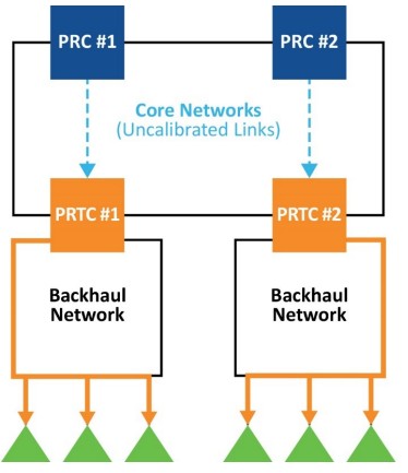
![]() Primary Path/Backup Path
Primary Path/Backup Path
![]() Optinal Frequency Reference used to secure GNSS failures
Optinal Frequency Reference used to secure GNSS failures
Note: T-GM are connected to the PRTC in this architecture
However, small PRTC distributed at the edge of the network as self-contained systems without a timing connection to the core are isolated from the upstream centralized clocks. This can be a problem for continued operation if the device loses GNSS connectivity as the oscillators used in such small PRTC will not normally be able to provide extensive holdover at ±100 ns level of accuracy.
Holding ±100 ns for extended periods of time is the domain of high-performance oscillators not of the low-cost OCXO or TCXO typically found in edge devices. Once a GNSS input is lost, then PRTC populated with such oscillators will quickly drift outside the ±100 ns specification. This is shown in the following two diagrams.
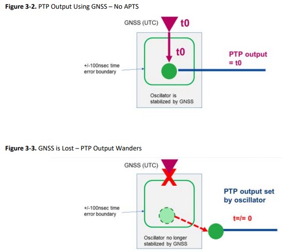
- If the Oscillator wanders the PTP output quickly loses the time reference
In normal circumstances once the GNSS is lost, as shown above, the PRTC immediately signals the loss of GNSS connectivity to the attached clients. This has ramifications for the eNB. In some client implementations, as soon as the PRTC signal’s GNSS connectivity is lost (by sending a clockClass7 flag, for example), the client will immediately disqualify the PTP input flow and go into holdover based on the internal oscillator in the radio device.
In this situation, if the oscillator in the RU is populated with a low-cost oscillator, it will not be able to remain within ±1.1 µs of UTC for more than a few minutes. All RU that disqualify the incoming PTP signal will drift independently. They will rapidly wander apart because the oscillators in each eNB will react differently to the individual environmental constraints and the speed, direction, and stability of the accumulating Time Error will be different for each RU. Moreover these radios will continue to generate RF and this will contribute to increasing and less controlled interference for other active RU in the vicinity from the same or other operators.
Assisted Partial Timing Support
To avoid a situation where the edge PRTC is isolated and in the event of a GNSS failure can no longer provide phase services, Microchip developed the idea of connecting the edge PRTC to the centralized core clocks using a PTP flow. This idea was adopted by the ITU-T and consented as Recommendation G.8273.4 – Assisted Partial Timing Support.
In this architecture, the incoming PTP flow is timestamped by the GNSS used by the core PRTC.
The PTP flow from the core PRTC to the edge PRTC is configured as a unicast protocol, G.8265.1 or G.8275.2. The PTP input is calibrated for Time Error using the local edge PRTC GNSS. This GNSS has the same reference (UTC) as the upstream GNSS. The incoming PTP flow can be considered as effectively a proxy GNSS signal from the core with traceability to UTC.
If the edge system GNSS now goes out of service for any reason, the edge PRTC can fall back onto the incoming calibrated PTP flow as the timing reference and continue to generate outbound PTP timestamps that are aligned with GNSS.
We can see this more clearly in the following figure.
Figure 4-1. PTP APTS Flows as a Backup for Edge PTRTC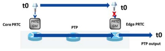
- Both GNSS have the same time reference (to)
- The PTP output uses the Edge PRTC GNSS for PTP output
The ITU-T formal statement of the G.8273.4 architecture is shown in the following figure.
Figure 4-2. ITU-T G.8273.4 Assisted Partial Timing Support Architecture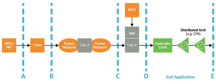
APTS Operation in Detail
APTS operation is quite a simple idea:
- Both the core PRTC and edge PRTC have a GNSS input referenced to UTC time.
- The core PRTC T-GM delivers PTP timestamps to the downstream edge PRTC/GM clock using a multicast or unicast PTP profile.
- The edge PRTC compares the PTP timestamp to the local GNSS time.
- The edge PRTC accumulates information about the PTP flow from the PTP timestamps and from message exchanges with the core PRTC. It thus understands the overall delay and Time Error on that specific input PTP path.
- The edge calibrates the incoming PTP flow by compensating for the accumulated Time Error so that it is now equivalent to the local GNSS time.
This process is shown in the following figure. This shows that the local GNSS is at “time 0”. The Time Error on the incoming PTP flow is removed using the GNSS reference and therefore is not at “time 0.”
Figure 5-1. APTS G.8273.4: A PTP Input Flow is Calibrated for Time Error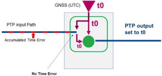 Once the APTS algorithm is operating, the incoming PTP flow can be used as a proxy for the upstream GNSS. If the GNSS on the local PRTC is lost, then the system will use the calibrated incoming APTS flow as the reference clock. This is shown on the following figure.
Figure 5-2. APTS/G.8273.4: If GNSS is Lost, the Calibrated PTP Input Can Be Used to Maintain the Reference Time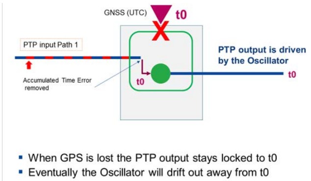 Even with APTS, however, if the GNSS stays disconnected then eventually the system oscillator will drift away from the ±100 ns PRTC requirement if an asymmetry profile not previously calibrated is introduced in the PTP APTS timing path.
One major weakness of the standard APTS implementation (G.8273.4) is that if the PTP path is re-routed while the GNSS is offline, the system will not have knowledge of the Time Error on the new path.
In other words, in the ITU-T standard, APTS is not resilient to a network re-arrangement that affects the incoming PTP flow. But, modern OTN- or MPLS-based core networks can be very dynamic with intermittent rearrangement of the network paths. This can clearly be a problem for PTP flows that are optimized for a single static path.
Engineering Resiliency – Protection Against PTP Input Path Rearrangement
An end-to-end PTP system can be made more resilient by calibrating more than one PTP path into the edge PRTC.
However, the G.8273.4 recommendation only mandates that additional PTP inputs have to be frequency corrected, not calibrated for Time Error.
While calibrating for frequency can help stabilize the edge PRTC oscillator, it is not a true representation of the upstream PRTC that requires a reference to UTC. Without a Time Error correction on more than one PTP input flow, the PTP clocking system is vulnerable to the dynamic network changes typical of a modern routed network. As the network rearranges the PTP paths, the edge system will lose the ability to track Time Error and compensate accordingly. As a result, the PRTC will move more quickly away from the ±100 ns limit with a frequency only compensated input than it will with a PTP flow that is well calibrated Time Error.
This is shown in the following two figures.
Figure 6-1. G.8273.4: The Second PTP Flow is Frequency Only Figure 6-2. A Purely Frequency-Disciplined Oscillator Will Drift Quickly Away from the Accepted PRTC TE Limit of ±100 ns
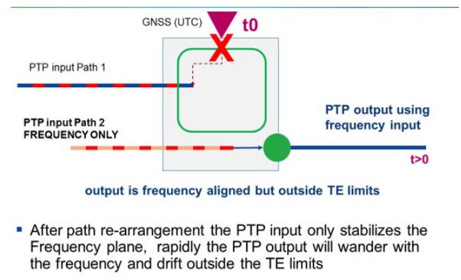 As can be seen above, the standard implementation assumes that the network is static and that the PRTC will always be able to rely on the incoming PTP flow to deliver a reference clock. However, modern asynchronous packet networks are dynamic; network rearrangements are quite common and PTP paths can and do change. One of the primary benefits of an MPLS or OTN network, in fact, is seamless reroutes without having to reserve alternative paths or provision extra bandwidth in the network. For frequency applications, this may not be a major problem, depending on the number of hops the PTP packets have to traverse. However, for a phase application that relies on well-engineered Time Error, a path change for the PTP flow carrying time information can be problematic. This is because the new path will almost certainly have a different Time Error from the original path.
Microchip has solved this problem by enhancing the G.8273.4 standard with Automatic Asymmetry Compensation (AAC), a patented method that allows Time Error compensation on up to 32 PTP paths per source PRTC clock.
Automatic Asymmetry Compensation (AAC)
Automatic Asymmetry Compensation as implemented by Microchip significantly enhances the standardized APTS algorithm. The following figure shows a simple representation of AAC.
Figure 7-1. APTS + AAC (Automatic Asymmetry Compensation)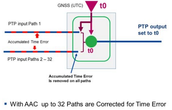 As we have discussed above, with G.8273.4 the system calibrates only one PTP input path. Under these circumstances, a Time Error calibration is only viable if the calibrated path is viable. If the path between the core and edge PRTC should change under rearrangement then the inherent Time Error will change and the path compensation or calibration is no longer viable.
With Automatic Asymmetry Compensation from Microchip, a PTP input path Time Error Table is maintained by the edge PRTC system for up to 32 input PTP flows. Each path is associated with the PTP master that provides the active flow. Moreover, in the case of Microchip edge PRTC and gateway clocks, multiple clients can operate on the same system, each with the potential to calibrate up to 32 input paths for Time Error.
Asymmetry Correction is Always On and Dynamic
Just because the PTP flow is calibrated, it does not mean it is providing correction to the PTP output.
If GNSS is driving the phase/time outputs, then the output is being driven by the GNSS not the incoming PTP flow. An important point here is that the ability to generate asymmetry table entries and have a calibrated path is completely unrelated to whether the current PTP path is driving the output or not. In other words, the APTS + AAC is always active, whatever the state of the local system, including the GNSS.
Note: Having paths entered in the TE table does not necessarily guarantee that the edge PRTC is currently (“at this moment”) able to provide asymmetry compensation. The ability to provide asymmetry compensation is simply stated as: “If (and only if) the current PTP flow has been signature matched with a table-entry, then (and only then) we are currently able to compensate for asymmetry.”
As it is continually in operation, the AAC function dynamically builds a history that enables the system to recall what has previously been seen. The table entries for asymmetry correction constitute a database that stores information about the PTP paths associated with the unique clock ID of the source PRTC. Moreover, each entry has a signature used for that path when GNSS is not available. Once identified, the stored asymmetry and offset (Time Error) associated with that path is applied every time that specific signature is seen.
Network rearrangement can affect the PTP input as it can cause significant change in PTP flow characteristics, such as a complete loss of flow, change in noise characteristics, or a change of round-trip time. When such a significant change occurs in the incoming PTP flow, it needs to be reevaluated and then, if the right criteria are met, it can become a calibrated path. Of course, new asymmetry path entries cannot be created without GNSS availability (which provides the calibration reference).
Figure 8-1. Microchip APTS + AAC – All PTP Paths Are Calibrated 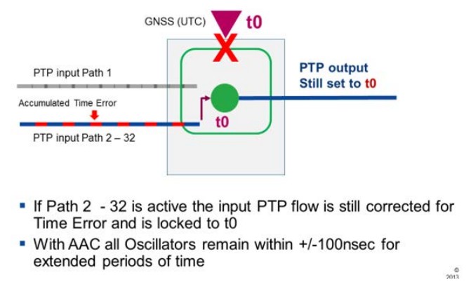
Behavior When Path is Not Calibrated for Time Error
If the PTP input is driving the PTP phase/time output, phase adjustment to UTC reference will occur if (and only if) the input is a calibrated path. If the PTP path has not been calibrated for Time Error using GNSS, then only frequency adjustments will be applied.
This behavior protects phase/time outputs from being impacted by unknown PTP asymmetry, which would occur if phase/time adjustments relied on a PTP path that had not been calibrated for Time Error.
Example of APTS AAC Operation
Consider the following scenario:
The system is initially running with GNSS and PTP, with Microchip AAC the asymmetry feature is automatically enabled. GNSS is driving the PTP outputs. All outputs are at t0 (time zero).
Assume the current PTP path has an offset correction (Time Error due to asymmetry) of +3 µs. This becomes the calibrated path.
The path is calibrated because the asymmetry adjustment (Time Error compensation) is automatically applied while the GNSS is active.
GNSS is then lost, so the PTP input path with a calibrated offset correction of +3 µs is the primary input and drives the phase output.
Now assume there is a change in the PTP input path caused by some network rearrangement phenomenon, such as a fiber cut. In this case, a completely different new PTP signature appears (for example, a change in round-trip time).
There are now two possible scenarios:
- If the system is using G,8273.4 as per the standard.
a. Since GNSS is not available to establish the asymmetry associated with the new path, it cannot be calibrated for TE. It will, however, be subject to frequency correction as per the standard. The result is that the phase output will quickly be impacted by GNSS loss. - If the system is using AAC enhanced G.8273.4.
a. Since GNSS is not available to establish the asymmetry associated with the new path, it cannot be calibrated for TE. However, if this new path has been previously seen, it will have a TE signature that allows the system to adjust to the new path. The result is that the phase output will not be impacted by GNSS loss.
There are now two main event possibilities:
- The original PTP path returns. This will cause further system rearrangement. Detection of the known signature will result in the use of the already calibrated PTP input. Active phase control resumes.
- GNSS returns. The system will operate as normal. As we have already stated, for AAC to be functional, the local GNSS must be qualified and operational because the GNSS input is used as the calibration value; PTP input paths are compared and validated against this value. However, once at least one table entry has occurred, the asymmetry feature can function without GNSS.
Manual Intervention of Limited Value
AAC implemented by Microchip enables user adjustment of phase-aligned outputs when PTP is the selected input reference. This allows for user compensation of known, static asymmetry in the PTP input path.
There are some use cases where it is possible to correct for a known fixed or constant Time Error.
For example, in a scenario where the path between the source PRTC and the edge PRTC is known to have a fixed rate conversion from 1GE to 100BASE-T. This rate conversion creates known asymmetry of about 6 µs, which would result in 3 µs of phase error (error due to asymmetry is always half of the difference in the path lengths).
To compensate manually, the user must know the asymmetry on the path, and this will require measurement. Thus, this configuration option is only viable when the asymmetry in the PTP path is both known and constant. If there is some dynamically changing asymmetry in the path, this capability is not helpful because it cannot adapt.
The strength of Microchip AAC on the other hand, is that it automatically detects and compensates for asymmetry without having to implement a separate measurement and inject a value manually.
Conclusion
Figure 12-1. Summary of APTS AAC Operation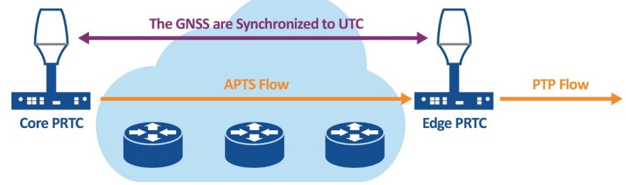 As mobile networks evolve from frequency-based networks to dense highly distributed radio heads that require phase alignment to provide advanced 5G services, it will be increasingly necessary to deploy PRTCs around the edge of the network. These PRTCs can be protected by implementing Assisted Partial Timing Support, G.8273.4, an engineering tool that can be used to back up the PRTC at the edge from a core PRTC.
However, the standard APTS algorithm is limited to providing Time Error correction for one PTP input flow, and therefore lacks a fundamental resiliency; that is, the ability to calibrate and use more than one PTP input path that has been corrected for Time Error.
Microchip has developed Automatic Asymmetry Compensation, a powerful enhancement to the standard APTS implementation that enables the edge PRTC to calibrate up to 96 different PTP input paths and therefore remain in operation even with significant and frequent changes in the transport network.
Microchip is focused on providing consistent, reliable tools that enable seamless operation of next generation clocking systems. APTS + AAC is yet another significant contribution in this long record of innovation.
Revision History
The revision history describes the changes that were implemented in the document. The changes are listed by revision, starting with the most current publication.
| Revision | Date | Description |
| A | 08/2024 | Initial Revision |
Microchip Information
The Microchip Website
Microchip provides online support via our website at www.microchip.com/. This website is used to make files and information easily available to customers. Some of the content available includes:
- Product Support – Data sheets and errata, application notes and sample programs, design resources, user’s guides and hardware support documents, latest software releases and archived software
- General Technical Support – Frequently Asked Questions (FAQs), technical support requests, online discussion groups, Microchip design partner program member listing
- Business of Microchip – Product selector and ordering guides, latest Microchip press releases, listing of seminars and events, listings of Microchip sales offices, distributors and factory representatives
Product Change Notification Service
Microchip’s product change notification service helps keep customers current on Microchip products. Subscribers will receive email notification whenever there are changes, updates, revisions or errata related to a specified product family or development tool of interest.
To register, go to www.microchip.com/pcn and follow the registration instructions.
Customer Support
Users of Microchip products can receive assistance through several channels:
- Distributor or Representative
- Local Sales Office
- Embedded Solutions Engineer (ESE)
- Technical Support
Customers should contact their distributor, representative or ESE for support. Local sales offices are also available to help customers. A listing of sales offices and locations is included in this document.
Technical support is available through the website at: www.microchip.com/support
Microchip Devices Code Protection Feature
Note the following details of the code protection feature on Microchip products:
- Microchip products meet the specifications contained in their particular Microchip Data Sheet.
- Microchip believes that its family of products is secure when used in the intended manner, within operating specifications, and under normal conditions.
- Microchip values and aggressively protects its intellectual property rights. Attempts to breach the code protection features of Microchip product is strictly prohibited and may violate the Digital Millennium Copyright Act.
- Neither Microchip nor any other semiconductor manufacturer can guarantee the security of its code. Code protection does not mean that we are guaranteeing the product is “unbreakable”. Code protection is constantly evolving. Microchip is committed to continuously improving the code protection features of our products.
Legal Notice
This publication and the information herein may be used only with Microchip products, including to design, test, and integrate Microchip products with your application. Use of this information in any other manner violates these terms. Information regarding device applications is provided only for your convenience and may be superseded by updates. It is your responsibility to ensure that your application meets with your specifications. Contact your local Microchip sales office for additional support or, obtain additional support at www.microchip.com/en-us/support/design-help/client-support-services.
THIS INFORMATION IS PROVIDED BY MICROCHIP “AS IS”. MICROCHIP MAKES NO REPRESENTATIONS OR WARRANTIES OF ANY KIND WHETHER EXPRESS OR IMPLIED, WRITTEN OR ORAL, STATUTORY OR OTHERWISE, RELATED TO THE INFORMATION INCLUDING BUT NOT LIMITED TO ANY IMPLIED WARRANTIES OF NON-INFRINGEMENT, MERCHANTABILITY, AND FITNESS FOR A PARTICULAR PURPOSE, OR WARRANTIES RELATED TO ITS CONDITION, QUALITY, OR PERFORMANCE.
IN NO EVENT WILL MICROCHIP BE LIABLE FOR ANY INDIRECT, SPECIAL, PUNITIVE, INCIDENTAL, OR CONSEQUENTIAL LOSS, DAMAGE, COST, OR EXPENSE OF ANY KIND WHATSOEVER RELATED TO THE INFORMATION OR ITS USE, HOWEVER CAUSED, EVEN IF MICROCHIP HAS BEEN ADVISED OF THE POSSIBILITY OR THE DAMAGES ARE FORESEEABLE. TO THE FULLEST EXTENT ALLOWED BY LAW, MICROCHIP’S TOTAL LIABILITY ON ALL CLAIMS IN ANY WAY RELATED TO THE INFORMATION OR ITS USE WILL NOT EXCEED THE AMOUNT OF FEES, IF ANY, THAT YOU HAVE PAID DIRECTLY TO MICROCHIP FOR THE INFORMATION.
Use of Microchip devices in life support and/or safety applications is entirely at the buyer’s risk, and the buyer agrees to defend, indemnify and hold harmless Microchip from any and all damages, claims, suits, or expenses resulting from such use. No licenses are conveyed, implicitly or otherwise, under any Microchip intellectual property rights unless otherwise stated.
Trademarks
The Microchip name and logo, the Microchip logo, Adaptec, AVR, AVR logo, AVR Freaks, BesTime, BitCloud, CryptoMemory, CryptoRF, dsPIC, flexPWR, HELDO, IGLOO, JukeBlox, KeeLoq, Kleer, LANCheck, LinkMD, maXStylus, maXTouch, MediaLB, megaAVR, Microsemi, Microsemi logo, MOST, MOST logo, MPLAB, OptoLyzer, PIC, picoPower, PICSTART, PIC32 logo, PolarFire, Prochip Designer, QTouch, SAM-BA, SenGenuity, SpyNIC, SST, SST Logo, SuperFlash, Symmetricom, SyncServer, Tachyon, TimeSource, tinyAVR, UNI/O, Vectron, and XMEGA are registered trademarks of Microchip Technology Incorporated in the U.S.A. and other countries.
AgileSwitch, ClockWorks, The Embedded Control Solutions Company, EtherSynch, Flashtec, Hyper Speed Control, HyperLight Load, Libero, motorBench, mTouch, Powermite 3, Precision Edge, ProASIC, ProASIC Plus, ProASIC Plus logo, Quiet-Wire, SmartFusion, SyncWorld, TimeCesium, TimeHub, TimePictra, TimeProvider, and ZL are registered trademarks of Microchip Technology Incorporated in the U.S.A.
Adjacent Key Suppression, AKS, Analog-for-the-Digital Age, Any Capacitor, AnyIn, AnyOut, Augmented Switching, BlueSky, BodyCom, Clockstudio, CodeGuard, CryptoAuthentication, CryptoAutomotive, CryptoCompanion, CryptoController, dsPICDEM, dsPICDEM.net, Dynamic Average Matching, DAM, ECAN, Espresso T1S, EtherGREEN, EyeOpen, GridTime, IdealBridge, IGaT, In-Circuit Serial Programming, ICSP, INICnet, Intelligent Paralleling, IntelliMOS, Inter-Chip Connectivity, JitterBlocker, Knob-on-Display, MarginLink, maxCrypto, maxView, memBrain, Mindi, MiWi, MPASM, MPF, MPLAB Certified logo, MPLIB, MPLINK, mSiC, MultiTRAK, NetDetach, Omniscient Code Generation, PICDEM, PICDEM.net, PICkit, PICtail, Power MOS IV, Power MOS 7, PowerSmart, PureSilicon, QMatrix, REAL ICE, Ripple Blocker, RTAX, RTG4, SAM-ICE, Serial Quad I/O, simpleMAP, SimpliPHY, SmartBuffer, SmartHLS, SMART-I.S., storClad, SQI, SuperSwitcher, SuperSwitcher II, Switchtec, SynchroPHY, Total Endurance, Trusted Time, TSHARC, Turing, USBCheck, VariSense, VectorBlox, VeriPHY, ViewSpan, WiperLock, XpressConnect, and ZENA are trademarks of Microchip Technology Incorporated in the U.S.A. and other countries.
SQTP is a service mark of Microchip Technology Incorporated in the U.S.A.
The Adaptec logo, Frequency on Demand, Silicon Storage Technology, and Symmcom are registered trademarks of Microchip Technology Inc. in other countries.
GestIC is a registered trademark of Microchip Technology Germany II GmbH & Co. KG, a subsidiary of Microchip Technology Inc., in other countries.
All other trademarks mentioned herein are property of their respective companies.
© 2024, Microchip Technology Incorporated and its subsidiaries. All Rights Reserved.
ISBN: 978-1-6683-0120-3
Quality Management System
For information regarding Microchip’s Quality Management Systems, please visit www.microchip.com/quality.
Worldwide Sales and Service
| AMERICAS | ASIA/PACIFIC | ASIA/PACIFIC | EUROPE |
| Corporate Office 2355 West Chandler Blvd. Chandler, AZ 85224-6199 Tel: 480-792-7200 Fax: 480-792-7277 Technical Support: www.microchip.com/support Web Address: www.microchip.com Atlanta Duluth, GA Tel: 678-957-9614 Fax: 678-957-1455 Austin, TX Tel: 512-257-3370 Boston Westborough, MA Tel: 774-760-0087 Fax: 774-760-0088 Chicago Itasca, IL Tel: 630-285-0071 Fax: 630-285-0075 Dallas Addison, TX Tel: 972-818-7423 Fax: 972-818-2924 Detroit Novi, MI Tel: 248-848-4000 Houston, TX Tel: 281-894-5983 Indianapolis Noblesville, IN Tel: 317-773-8323 Fax: 317-773-5453 Tel: 317-536-2380 Los Angeles Mission Viejo, CA Tel: 949-462-9523 Fax: 949-462-9608 Tel: 951-273-7800 Raleigh, NC Tel: 919-844-7510 New York, NY Tel: 631-435-6000 San Jose, CA Tel: 408-735-9110 Tel: 408-436-4270 Canada – Toronto Tel: 905-695-1980 Fax: 905-695-2078 |
Australia – Sydney Tel: 61-2-9868-6733 China – Beijing Tel: 86-10-8569-7000 China – Chengdu Tel: 86-28-8665-5511 China – Chongqing Tel: 86-23-8980-9588 China – Dongguan Tel: 86-769-8702-9880 China – Guangzhou Tel: 86-20-8755-8029 China – Hangzhou Tel: 86-571-8792-8115 China – Hong Kong SAR Tel: 852-2943-5100 China – Nanjing Tel: 86-25-8473-2460 China – Qingdao Tel: 86-532-8502-7355 China – Shanghai Tel: 86-21-3326-8000 China – Shenyang Tel: 86-24-2334-2829 China – Shenzhen Tel: 86-755-8864-2200 China – Suzhou Tel: 86-186-6233-1526 China – Wuhan Tel: 86-27-5980-5300 China – Xian Tel: 86-29-8833-7252 China – Xiamen Tel: 86-592-2388138 China – Zhuhai Tel: 86-756-3210040 |
India – Bangalore Tel: 91-80-3090-4444 India – New Delhi Tel: 91-11-4160-8631 India – Pune Tel: 91-20-4121-0141 Japan – Osaka Tel: 81-6-6152-7160 Japan – Tokyo Tel: 81-3-6880- 3770 Korea – Daegu Tel: 82-53-744-4301 Korea – Seoul Tel: 82-2-554-7200 Malaysia – Kuala Lumpur Tel: 60-3-7651-7906 Malaysia – Penang Tel: 60-4-227-8870 Philippines – Manila Tel: 63-2-634-9065 Singapore Tel: 65-6334-8870 Taiwan – Hsin Chu Tel: 886-3-577-8366 Taiwan – Kaohsiung Tel: 886-7-213-7830 Taiwan – Taipei Tel: 886-2-2508-8600 Thailand – Bangkok Tel: 66-2-694-1351 Vietnam – Ho Chi Minh Tel: 84-28-5448-2100 |
Austria – Wels Tel: 43-7242-2244-39 Fax: 43-7242-2244-393 Denmark – Copenhagen Tel: 45-4485-5910 Fax: 45-4485-2829 Finland – Espoo Tel: 358-9-4520-820 France – Paris Tel: 33-1-69-53-63-20 Fax: 33-1-69-30-90-79 Germany – Garching Tel: 49-8931-9700 Germany – Haan Tel: 49-2129-3766400 Germany – Heilbronn Tel: 49-7131-72400 Germany – Karlsruhe Tel: 49-721-625370 Germany – Munich Tel: 49-89-627-144-0 Fax: 49-89-627-144-44 Germany – Rosenheim Tel: 49-8031-354-560 Israel – Hod Hasharon Tel: 972-9-775-5100 Italy – Milan Tel: 39-0331-742611 Fax: 39-0331-466781 Italy – Padova Tel: 39-049-7625286 Netherlands – Drunen Tel: 31-416-690399 Fax: 31-416-690340 Norway – Trondheim Tel: 47-72884388 Poland – Warsaw Tel: 48-22-3325737 Romania – Bucharest Tel: 40-21-407-87-50 Spain – Madrid Tel: 34-91-708-08-90 Fax: 34-91-708-08-91 Sweden – Gothenberg Tel: 46-31-704-60-40 Sweden – Stockholm Tel: 46-8-5090-4654 UK – Wokingham Tel: 44-118-921-5800 Fax: 44-118-921-5820 |
![]() White Paper
White Paper
© 2024 Microchip Technology Inc. and its subsidiaries
DS00005550A
Documents / Resources
 |
MICROCHIP Assuring Mobile Services with Assisted Partial Timing Support White Paper [pdf] Instructions DS00005550A, Assuring Mobile Services with Assisted Partial Timing Support White Paper, Mobile Services with Assisted Partial Timing Support White Paper, Services with Assisted Partial Timing Support White Paper, Assisted Partial Timing Support White Paper, Partial Timing Support White Paper, Timing Support White Paper, Support White Paper, Paper |