![]() Quick installation
Quick installation
CZone – MasterBus Bridge Interface
CZone MasterBus Bridge Interface
 This Quick installation guide provides a brief overview of the CZone – MasterBus Bridge Interface installation. Refer to the CZone Configuration Tool Instructions, for information on how to setup the MasterBus Bridge Interface (MBI).
 Safety instructions
• Use the MBI following the instructions and specifications stated in this document.
• Only use the MBI in a technical correct condition.
• Do not work on an electrical system if it is still connected to a current source.
NAVICO GROUP does not hold itself liable for:
• Damage resulting from the use of the MBI;
• Possible errors in the included manual and the consequences of these;
• Use that is inconsistent with the purpose of the product.- Check the contents of the delivery. Contact your supplier if one of the items is missing.
Do not use the MBI if it is damaged!
CZone – MasterBus Bridge Interface MasterBus adapter
 MasterBus Terminator
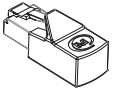
- Select a location where the surface material is sturdy, and the LED can be seen.
The minimum installation height including connectors is 10cm [4″].
A. Remove the lower mounting plate from the MBI to use as a template and mark the position of the four holes to be drilled. Drill the holes (3.5mm [9/16″]).
B. Secure the two blind holes of the base with two (short 4mm) screws.
C. Mount the MBI to its bottom plate and fix with two (long 4mm) screws.
- Secure the battery in place. Choose the option that best fits the position.
Wire the interface like indicated. The CZone connector must be plugged at the left-hand side (5), the MasterBus connector at the right (6). Notice the polarization nock (10). 1. CZone terminator
2. CZone devices
3. Bridge Interface
4. LED
5. CZone connector *
6. MasterBus connector
7. Adapter including cable
8. MasterBus terminator
9. MasterBus devices
10. Polarization nock
* can also be used to connect to an NMEA2000 network, enabling basic data exchange.
 Ensure that each end of both networks has a terminator.
 - Check if the CZone – MasterBus Bridge Interface works correctly.

LED (4) functions:
Green: Active/OK, CZone (5) and MasterBus (6) connected.
Orange flashing: Traffic, communication.
Red: Fault, no connection.
If there is no connection, first check the cables, then the configuration of the CZone and MasterBus networks.
SPECIFICATIONS
| MODEL: | CZONE MASTERBUS BRIDGE INTERFACE |
| Product code: | 80-911-0072-00 |
| Delivered with: | MasterBus cable adapter, MasterBus Terminator |
| Current consumption: | 60 mA, 720 mW |
| MasterBus Powering: | No |
| Din rail mounting: | No |
| Protection degree: | IP65 |
| Weight: | 145g [0.3 lb], excluding cable adapter |
| Dimensions: | 69 x 69 x 50 mm [2.7 x 2.7 x 2.0 inch] |
![]() Do not dispose of with normal household waste!
Do not dispose of with normal household waste!
Act according to local rules.
![]() NAVICO GROUP EMEA, P.O.Box 22947,
NAVICO GROUP EMEA, P.O.Box 22947,
NL-1100 DK Amsterdam, The Netherlands.
Web: www.mastervolt.com [10000002866_01]
Documents / Resources
 |
Mastervolt CZone MasterBus Bridge Interface [pdf] Instruction Manual 80-911-0072-00, CZone MasterBus Bridge Interface, CZone, MasterBus Bridge Interface, Bridge Interface, Interface |