
 AtomS3 Lite
User Manual
Outline
AtomS3 Lite is a development board based on the ESP32-S3 chip. The board is equipped with two buttons and USB-C ports, in addition to WS2812LED and 2.4g antenna.

1.1 Hardware Composition
AtomS3 Lite hardware: ESP32-S3 chip, color LED, buttons, Y8089DCDC.
Esp32-s3 is a single chip integrated with 2.4ghz Wi-Fi and Bluetooth (LE), with Long Range mode. Esp32-s3 is equipped with Xtensa® 32-bit LX7 dual-core processor, up to 240mhz, built-in 512KB SRAM (TCM), 45 programmable GPIO pins, and rich communication interfaces. Esp32-s3 supports a larger capacity of high-speed octal SPI Flash and off-chip RAM, and supports user-configured data caching and instruction caching.
The power management chip is SY8089 of Silergy. Working voltage range is 2.7V~5.5V, charging current is 2A.
AtomS3 Lite comes with everything you need to program ESP32, everything you need to do and develop
PIN DESCRIPTION
2.1. USB INTERFACE
AtomS3 Lite is configured with type-c USB interface and supports THE USB2.0 standard communication protocol。

2.2. GROVE INTERFACE
4P is equipped with M5CAMREA GROVE interface with spacing of 2.0mm. Internal wiring is connected to GND, 5V, GPIO36 and GPIO37.

2.3. GPIO INTERFACE

5p is equipped with a 2.54mm spacing busbar interface, and internal wiring is connected to GPIO14, GPIO17, GPIO42, GPIO40, and 3.3V.

The 4p is configured with 2.54mm spacing bus ports, and the internal cables are GPIO38, GPIO39, 5V, and GND.
FUNCTIONAL DESCRIPTION
This chapter describes the ESP32-S3 various modules and functions.
3.1. CPU AND MEMORY
Xtensa® dual-core 32-bit LX7 microprocessor,up to 240 MHz
- 384 KB ROM
- 512 KB SRAM
- 16 KB SRAM in RTC
- SPI, Dual SPI, Quad SPI, Octal SPI, QPI and OPI interfaces that allow connection to multiple flash and external RAM
- Flash controller with cache is supported
- Flash in-Circuit Programming (ICP) is supported
3.2. STORAGE DESCRIPTION
3.2.1. External Flash and RAM
ESP32-S3 supports SPI, Dual SPI, Quad SPI, Octal SPI, QPI and OPI interfaces that allow connection to multiple external flash and RAM.
The external flash and RAM can be mapped into the CPU instruction memory space and read-only data memory space. The external RAM can also be mapped into the CPU data memory space. ESP32-S3 supports up to 1GB of external flash and RAM, and hardware encryption/decryption based on XTS-AES to protect users’programs and data in flash and external RAM.
Through high-speed caches, ESP32-S3 can support at a time up to:
- External flash or RAM mapped into 32 MB instruction space as individual blocks of 64 KB
- External RAM mapped into 32 MB data space as individual blocks of 64 KB. 8-bit, 16-bit, 32-bit, and 128-bit reads and writes are supported. External flash can also be mapped into 32 MB data space as individual blocks of 64 KB, but only supporting 8-bit, 16-bit, 32- bit and 128-bit reads.
3.3. CPU CLOCK
The CPU clock has three possible sources:
- External main crystal clock
- Internal fast RC oscillator (typically about 17.5 MHz, and adjustable)
- PLL clock
The application can select the clock source from the three clocks above.
The selected clock source drives the CPU clock directly, or after division, depending on the application. Once the CPU is reset, the default clock source would be the external main crystal clock divided by 2.
3.4. RTC AND LOWPOWER MANAGEMENT
With the use of advanced power-management technologies, ESP32-S3 can switch between different power modes. (see table1)。
- Active mode: CPU and chip radio are powered on. The chip can receive, transmit, or listen.
- Modemsleep mode: The CPU is operational and the clock speed can be reduced. The wireless baseband and radio are disabled, but wireless connection can remain active.
- Lightsleep mode: The CPU is paused. The RTC peripherals, as well as the ULP coprocessor can be woken up periodically by the timer. Any wake-up events (MAC, host, RTC timer, or external interrupts) will wake up the chip. Wireless connection can remain active. Users can optionally decide what peripherals to shut down/keep on (refer to Figure 1), for power-saving purpose.
- Deepsleep mode: CPU and most peripherals are powered down.
Only the RTC memory is powered on and RTC peripherals are optional. Wi-Fi connection data are stored in the RTC memory. The ULP coprocessor is functional.
Current Consumption in LowPower Modes: TABLE 1
| Work mode | Description | Typ (µA) |
| Light-sleep | VDD_SPI and Wi-Fi are powered down, and all GPIOs are high-impedance. | 240¹ |
| Deep-sleep | RTC memory and RTC peripherals are powered on. | 8 |
| RTC memory is powered on. RTC peripherals are powered off. | 7 | |
| Power off | CHIP_PU is set to low level. The chip is powered off. | 1 |
ELECTRICAL CHARACTERISTICS
4.1. ABSOLUTE MAXIMUM RATINGS
Table 2: Absolute Maximum Ratings
| Symbol | Parameter | Min | Max | Unit |
| VDDA, VDD3P3, VDD3P3_RTC, VDD3P3_CPU, VDD_SPI |
Voltage applied to power supply pins per power domain | 0. | 4. | V |
| I output * | Cumulative I0 output current | — | 1500 | mA |
| T STORE | Storage temperature | -40 | 150 | °C |
- VIO to the power supply pad, Refer ESP32 Technical Specification Appendix IO_MUX, as SD_CLK of Power supply for VDD_SDIO.
4.2. WIFI RADIO AND BASEBAND
The ESP32-S3 Wi-Fi radio and baseband support the following features:
- 802.11b/g/n
- 802.11n MCS0-7 that supports 20 MHz and 40 MHz bandwidth
- 802.11n MCS32
- 802.11n 0.4 μs guard-interval
- Data rate up to 150 Mbps
- RX STBC (single spatial stream)
- Adjustable transmitting power
- Antenna diversity:
ESP32-S3 supports antenna diversity with an external RF switch. This switch is controlled by one or more
GPIOs, and used to select the best antenna to minimize the effects of channel imperfections.
4.3. BLUETOOTH LE RF TRANSMITTER (TX) SPECIFICATIONS
Table 3: Transmitter Characteristics Bluetooth LE 1 Mbps
| Parameter | Description | Min | Typ | Max | Unit |
| RF transmit power | RF power control | — | — | 5.80 | dBm |
| Carrier frequency offset and drift |  |
— | 2.50 | — | kHz |
| — | 2.00 | — | kHz | ||
| — | 1.39 | — | kHz | ||
| — | 0.80 | — | kHz | ||
| Modulation characteristics |  |
— | 249.00 | — | kHz |
Min (for at least 99.9% of all ) (for at least 99.9% of all ) |
— | 198.00 | — | kHz | |
 |
— | 0.86 | — | — | |
| In-band spurious emissions | ±2 MHz offset | — | -37.00 | — | dBm |
| ±3 MHz offset | — | -42.00 | — | dBm | |
| >±3 MHz offset | — | -44.00 | — | dBm |
4.4. BLUETOOTH LE RF RECEIVER (RX) SPECIFICATIONS
Table 35: Receiver Characteristics Bluetooth LE 1 Mbps
| Parameter | Description | Min | Typ | Max | Unit |
| Sensitivity 030.8% PER | — | — | -98. | — | dBm |
| Maximum received signal @30.8% PER | — | — | 8 | — | dBm |
| Co-channel C/I | F = FO MHz | 9 | — | dB | |
| Adjacent channel selectivity C/I | F = FO + 1 MHz | -3 | — | dB | |
| F = FO – 1 MHz | -3 | — | dB | ||
| F = FO + 2 MHz | — | -28 | — | dB | |
| F = FO – 2 MHz | — | -30 | — | dB | |
| F = FO + 3 MHz | — | -31 | — | dB | |
| F = FO – 3 MHz | — | -33 | — | dB |
QUICK START
1.1. ARDUINO IDE
Visit Arduino’s official website(https://www.arduino.cc/en/Main/Software),Select the installation package for your own operating system to download.
>1.Open up Arduino IDE, navigate to `File`->`Peferences`->`Settings`
>2.Copy the following M5Stack Boards Manager url to `Additional Boards Manager URLs:` https://raw.githubusercontent.com/espressif/arduino-esp32/gh-pages/package_esp32_dev_index.json
>3.Navigate to `Tools`->`Board:`->`Boards Manager…`
>4.Search `ESP32` in the pop-up window, find it and click `Install`
>5.select `Tools`->`Board:`->`ESP32-Arduino-ESP32 DEV Module
 1.2. BLUETOOTH SERIAL
Open the Arduino IDE and open the example program
`File`->`Examples`->`BluetoothSerial`->`SerialToSerialBT`. Connect the device to the computer and select the corresponding port to burn. After completion, the device will automatically run Bluetooth, and the device name is `ESP32test`. At this time, use the Bluetooth serial port sending tool on the PC to realize the transparent transmission of Bluetooth serial data.


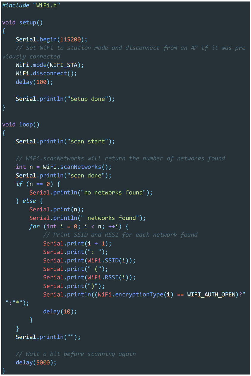
1.3. WIFI SCANNING
Open the Arduino IDE and open the example program
`File`->`Examples`->`WiFi`->`WiFiScan`. Connect the device to the computer and select the corresponding port to burn. After completion, the device will automatically run the WiFi scan, and the current WiFi scan result can be obtained through the serial port monitor that comes with the Arduino.

FCC Statement
Any Changes or modifications not expressly approved by the party responsible for compliance could void the user’s authority to operate the equipment.
This device complies with part 15 of the FCC Rules. Operation is subject to the following two conditions:
- This device may not cause harmful interference, and
- This device must accept any interference received, including interference that may cause undesired operation.
FCC Radiation Exposure Statement:
This equipment complies with FCC radiation exposure limits set forth for an uncontrolled environment .This equipment should be installed and operated with minimum distance 20cm between the radiator& your body.
Note : This equipment has been tested and found to comply with the limits for a Class B digital device, pursuant to part 15 of the FCC Rules.
These limits are designed to provide reasonable protection against harmful interference in a residential installation. This equipment generates,uses and can radiate radio frequency energy and, if not installed and used in accordance with the instructions, may cause harmful interference to radio communications. However, there is no guarantee that interference will not occur in a particular installation. If this equipment does cause harmful interference to radio or television reception, which can be determined by turning the equipment off and on, the user is encouraged to try to correct the interference by one or more of the following measures:
- Reorient or relocate the receiving antenna.
- Increase the separation between the equipment and receiver.
- Connect the equipment into an outlet on a circuit different from that to which the receiver is connected.
- Consult the dealer or an experienced radio/TV technician for help.
V0.01
Documents / Resources
 | AtomS3 Lite |
References
- raw.githubusercontent.com/espressif/arduino-esp32/gh-raw.githubusercontent.com
- ESP32 Downloader Kit | m5stack-storeshop.m5stack.com
- arduino.cc/en/Main/Softwarewww.arduino.cc
- User Manualmanual.tools
ATOMS3 Lite ESP32S3 Dev-Kit: Nach einem flash versuch via esp home reagiert der stack nicht mehr. wie kann ich ihn resetten?
How do I reset the M5Stack AtomS3 Lite after a failed flash attempt via ESPHome?
If your M5Stack AtomS3 Lite is unresponsive after a failed flash attempt, you can force it into Download Mode to reset and re-flash the firmware. Follow these steps:
Note: According to the manual, once the CPU is reset, the default clock source is the external main crystal clock divided by 2. If the device still does not respond, ensure you have the correct ESP32-S3 board drivers installed in your development environment.
Read the full Q&A page