![]() PX0406 RDM RGBW Decoder
PX0406 RDM RGBW Decoder
Instruction Manual

Summary
Welcome to using the PX series DMX512/RDM decoder & driver. PX series adopt the advanced micro-computer control technology and converted the DMX512, RDM/2009 digital signal widely used international to the PWM control signal. 1~4 channels output for option and each channel able to achieve 256 gradations of control, and also it can be used as the connector of PC digital light controller and analog light modulator. It is mainly used for controlling buildings & lights applied LED.
Product Features
- Meets DMX512/1990, RDM /2009 protocol
- Supported RDM parameters:
DISC_UNIQUE_BRANCH
DISC_MUTE
DISC_UN_MUTE DEVICE_INFO
Dimension(mm)
SOFTWARE_VERSION_LABEL
DMX512/RDM_START_ADDRESS
IDENTIFY_DEVICE
MANUFACTURER_LABEL
SUPPORTED_PARAMETERS - In DMX mode set the DMX address manually by the switch; in RDM mode, the host computer address allocation
- Constant voltage output, the maximum current of 6A /ch for RGBW decoder
- 256-grade brightness adjustment
- Short-circuit protection,overload protection,over-temperature protection
- Flicker-free
Technical Parameters
| Model | PX 0406 | |
| Output | Channels | 1-4 |
| Voltage | 1 2-24VDC | |
| Current | 6A*4CH | |
| Power | 288W(1 2V)/576W(24V) | |
| Input | Voltage | 1 2- 24VDC |
| Standby loss | < 1W | |
| Control signal | DMX5 1 2 1 990/RDM 2009 | |
| Others | Dimension | 1 40*50*26mm ( L * W* H) |
| Packing size | 145*56*32 mm ( L * W* H) | |
| G.W. | 240g | |
| Operation temperature | – 20 50°C | |
| Relative humidity | 20% -90%RH | |
Dimension(mm)
 Interface Description
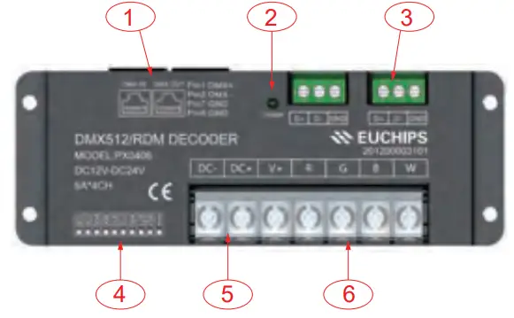
- RJ45 Signal input and output interfaces
- Signal light
- Euro terminal blocks
- Address setting interface
- Power input interface (reverse connection of input will damage the driver, make sure the wiring is correct before power on.)
- Output interface
Remark
Connect the anode and RGBW wire of the common anode RGBW module to the output interface of the decoder directly; Connect the anode wire of the single-color module to V+ on the decoder, and connect the cathode wire to one of the RGBW pin according to the LED’s color; Connect several colors single-color module to one decoder, please connect their anode wires to V+ pin on the decoder.
DIP Switch Setting
| DIP] | DIP2 | DIPS | DIP4 | DIP5 | DIP6 | DIP7 | DIPS | DIP9 | DIP10 | |
| OFF | 0 | 0 | 0 | 0 | 0 | 0 | 0 | 0 | 0 | NA |
| ON | 1 | 2 | 4 | 8 | 16 | 32 | 64 | 128 | 256 | FUN |
DIP1~9: Setting the first DMX address of the device the sum of the number shown in the table above is the first DMX address of the device.
In DMX mode, the effective address is 1-511, and 511 is for fixed mode (511 means output RGBW gradient).
When the address is 0, the default is RDM mode.
DIP10: FUN is 120-ohm terminal resistance.
Wiring Diagram

- Use the CAT-5 cable or three-core shielded cable as DMX512/ RDM signal cable and DMX512/RDM signal has the positive and negative signal. While welding the DMX512/RDM signal cable plug, there must pay much attention to distinguishing between positive (+) and negative(-), and then connect the DMX512/RDM signal cable with the corresponding input interface of PX0406 correctly.
- Refer to the “DMX Series of address dial code table” to set the DMX address by dip-switch.
- Connect a signal terminal at the end of the whole connection.

Documents / Resources
 |
LUCAS LED PX0406 RDM RGBW Decoder [pdf] Instruction Manual PX0406, RDM RGBW Decoder, PX0406 RDM RGBW Decoder, RGBW Decoder, Decoder |


