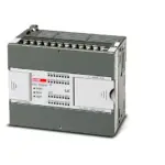
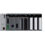
LS-ELECTRIC GPL-D22C Programmable Logic Controller
INSTALLATION GUIDE
MODEL: GPL-D22C,D24C,DT4C/C1 GPL-TR2C/C1,TR4C/C1,RY2C
This installation guide provides simple function information or PLC control. Please read carefully this data sheet and manuals before using products. Especially read precautions then handle the products properly
1. Safety Precautions
Meaning of warning and caution label
WARNING
WARNING indicates a potentially hazardous situation which, if not avoided, could result in death or serious injury
CAUTION indicates a potentially hazardous situation which, if not avoided, may result in minor or moderate injury.
It may also be used to alert against unsafe practices
WARNING
① Do not contact the terminals while the power is applied.
② Be sure there are no foreign metallic matters.
③ Do not manipulate the battery(charge, disassemble, hitting, short, soldering).
CAUTION
① Be sure to check the rated voltage and terminal arrangement before wiring
② When wiring, tighten the screw of terminal block with the specified torque range
③ Do not install the flammable things on surroundings
④ Do not use the PLC in the environment of direct vibration
⑤ Except expert service staff, do not disassemble or fix or modify the product
⑥ Use the PLC in an environment that meets the general specifications contained in this datasheet.
⑦ Be sure that external load does not exceed the rating of output module.
⑧ When disposing of PLC and battery, treat it as industrial waste.
⑨ I/O signal or communication line shall be wired at least 100mm away from a highvoltage cable or power line.
2. Operating Environment
To install, observe the below conditions.

3. Accessories and Cable Specifications
■ Check Profibus Connector contained in the box
1) Usage : Profibus Communication Connector
2) Item : GPL-CON
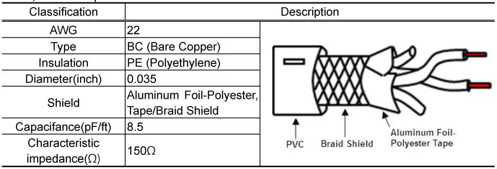
■ When using Pnet communication, shielded twisted pair cable shall be used with consideration of communication distance and speed.
1) Manufacturer : Belden or the maker of equivalent material specification below
2) Cable Specification
4. Dimension (mm)
■ This is front part of the product. Refer to each name when operating the system. For more information, refer to user’s manual.
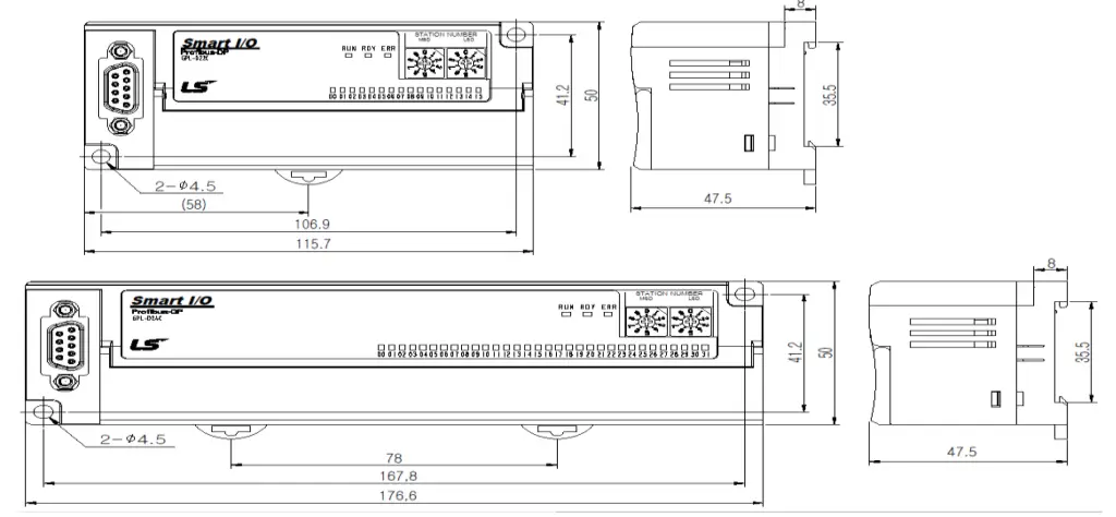
■ LED Details
| Name | Description |
| PWR | Displays the status of power |
| RDY | Displays the interface status of communication module |
| ERR | Displays the network status of communication module |
5. Performance Specifications
■ This is performance specifications of the product. Refer to each name when driving the system. For more information, refer to user manual.

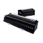
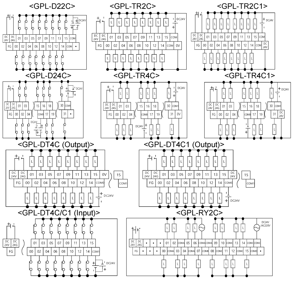
6. Terminal Block Layout for I/O Wiring
■ This is terminal block layout for I/O wiring. Refer to each name when driving the system.
For more information, refer to user manual.
7. Wiring
■ Connector structure and wiring method
1) Input line: green line is connected to A1, red line is connected to B1
2) Output line: green line is connected to A2, red line is connected to B2
3) Connect shield to clamp of shield
4) In case of installing the connector at terminal, install the cable at A1, B1

8. Warranty
■ The warranty period is 36 months from the date of manufacture.
■ The initial diagnosis of faults should be conducted by the user. However, upon request, LS ELECTRIC or its representative(s) can undertake this task for a fee. If the cause of the fault is
found to be the responsibility of LS ELECTRIC, this service will be free of charge.
■ Exclusions from warranty
1) Replacement of consumable and life-limited parts (e.g. relays, fuses, capacitors, batteries, LCDs, etc.)
2) Failures or damages caused by improper conditions or handling outside those specified in the user manual
3) Failures caused by external factors unrelated to the product
4) Failures caused by modifications without LS ELECTRIC’s consent
5) Use of the product in unintended ways
6) Failures that cannot be predicted/solved by current scientific technology at the time of manufacture
7) Failures due to external factors such as fire, abnormal voltage, or natural disasters
8) Other cases for which LS ELECTRIC is not responsible
■ For detailed warranty information, please refer to the user’s manual.
■ The content of the installation guide is subject to change without notice for product performance improvement.
LS ELECTRIC Co., Ltd.
0310000310 V4.5 (2024.6)
• E-mail: automation@ls-electric.com
• Headquarter/Seoul Office Tel: 82-2-2034-4033,4888,4703
• LS ELECTRIC Shanghai Office (China) Tel: 86-21-5237-9977
• LS ELECTRIC (Wuxi) Co., Ltd. (Wuxi, China) Tel: 86-510-6851-6666
• LS-ELECTRIC Vietnam Co., Ltd. (Hanoi, Vietnam) Tel: 84-93-631-4099
• LS ELECTRIC Middle East FZE (Dubai, U.A.E.) Tel: 971-4-886-5360
• LS ELECTRIC Europe B.V. (Hoofddorf, Netherlands) Tel: 31-20-654-1424
• LS ELECTRIC Japan Co., Ltd. (Tokyo, Japan) Tel: 81-3-6268-8241
• LS ELECTRIC America Inc. (Chicago, USA) Tel: 1-800-891-2941
• Factory: 56, Samseong 4-gil, Mokcheon-eup, Dongnam-gu, Cheonan-si, Chungcheongnamdo, 31226, Korea
Specifications
- C/N: 10310000310
- Product: Programmable Logic Controller – Smart I/O Pnet
- Models: GPL-D22C, D24C, DT4C/C1, GPL-TR2C/C1, TR4C/C1,
RY2C
FAQ
Q: What do the numerical values in the text-extract signify?
A: The numerical values likely represent parameters or readings specific to the PLC operation, such as temperature, humidity, or signal levels.
Documents / Resources
 |
LS-ELECTRIC GPL-D22C Programmable Logic Controller [pdf] Installation Guide GPL-D22C, D24C, DT4C-C1, GPL-TR2C-C1, TR4C-C1, RY2C, GPL-D22C Programmable Logic Controller, GPL-D22C, Programmable Logic Controller, Logic Controller |