
SCRIBE
Setup Guide

![]()
WHAT’S IN THE BOX

Camera Unit
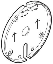
Camera Mounting Bracket

Mounting Template

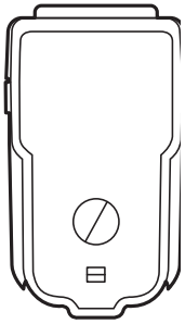
Share Button

Power Injector

Dongle Transceiver

CAT5e Cables

Cable Clips

Boundary Stickers
IEC C8 Power Cord Adapter

Molly Bolts

Wood Screws
CAMERA I/O


CONNECTIONS OVERVIEW

RECOMMENDED CAMERA PLACEMENT HEIGHT
If needed, apply boundary stickers to mark the max capture area.

STEP 1: ATTACH THE CAMERA MOUNTING BRACKET
Mark screw hole locations using the mounting template.
1
![]()
 2
2
STEP 2: PLUG IN THE CAT5E CABLE AND CHOOSE A ROUTING OPTION


STEP 3: ATTACH THE CAMERA ONTO THE CAMERA MOUNTING BRACKET


STEP 4: CONNECT THE CAT5E CABLE TO THE POWER INJECTOR
Insert cable connected to camera to “OUT”.


STEP 5: CONNECT THE POWER INJECTOR TO A POWER OUTLET


STEP 6: CONNECT SECOND CAT5E CABLE TO THE POWER INJECTOR
Insert cable connected to camera to “IN”.


STEP 7: CONNECT THE OTHER END TO THE DONGLE TRANSCEIVER.
PLUG THE DONGLE TRANSCEIVER INTO THE MEETING ROOM PC.
![]()


RECOMMENDED BUTTON PLACEMENT HEIGHT
Install the button 30”- 48” from the floor.

STEP 8: INSTALL SHARE BUTTON
![]() Remove the battery pull tabs only after you have mounted Share Button to the wall.
Remove the battery pull tabs only after you have mounted Share Button to the wall.
1 2 3


STEP 9: START WHITEBOARD SHARING FROM MEETING ROOM TOUCH CONTROLLER

STEP 10: CONFIRM CALIBRATION TO FINISH SETUP
If calibration is correct, press the Share button to confirm. If calibration is incorrect, download Logitech Sync to adjust boundaries. logitech.com/sync.

![]()

![]()
STEP 11: READY TO GO!
Press Share Button to easily start/stop whiteboard sharing into meetings.

www.logitech.com/support
© 2021 Logitech, Logi and the Logitech Logo are trademarks or registered trademarks of Logitech Europe S.A. and/or its affiliates in the U.S. and other countries. All other trademarks are the property of their respective owners. Logitech assumes no responsibility for any errors that may appear in this manual. Information contained herein is subject to change without notice.
620-010125 003
Documents / Resources
 | SCRIBE |
References
- Sync | Video Conferencing Device Management Softwarelogitech.com
- Logitech Customer Support & Business Supportwww.logitech.com
- User Manualmanual.tools