![]() CLS-1 UltraSonic Clear LabelSensor
CLS-1 UltraSonic Clear LabelSensor
Instruction Manual
Specifications
SUPPLY VOLTAGE
- 12 to 30 VDC
- Polarity Protected
Note: For use in Class 2 Circuits
CURRENT REQUIREMENTS
- 95mA @ 12 VDC, 45mA @ 30 VDC
DIGITAL OUTPUTS
- (1) NPN and (1) PNP open collector output 150mA Max; <2V Residual Voltage
(Note: On CLSC-1M8, NPN & PNP are software selectable). - All outputs are continuously short circuit protected
REMOTE AUTOSET INPUT
- Momentary sinking or sourcing input; 1.2mA max; Software Selectable
DIAGNOSTIC INDICATORS
- OLED Graphic Display – Includes Contrast Indicator, Numerical Display, Set Point and Trigger Point, and all sensor options and modes.
- Red LED Output Indicator– Illuminates when the sensor’s output transistors are “ON”.
Note: If output LED flashes on power up, a short circuit condition exists.
PUSHBUTTON CONTROL
- Three (3) push button controls
- Gap (for Gap AUTOSET)
- Label (for multi-layered labels)
- Menu (for accessing Options)
HYSTERESIS
- Dynamic – adjusted by AUTOSET
RESPONSE TIME
- 200μs
REPEATABILITY
- 125μs
AMBIENT TEMPERATURE
- 4°C to 50°C (39°F to 122°F)
RUGGED CONSTRUCTION
- Chemical resistant, high impact Aluminum housing
- Waterproof ratings: NEMA 4X, 6P and IP65
- Conforms to heavy industry grade CE requirements
THRESHOLD SET
- 1-Point, 2-Point, or Dynamic AUTOSET; manually or remotely.
THRESHOLD ADJUST
- Manual or AUTO Adjust
OUTPUT TIMERS
- On Delay, Off Delay, One Shot, or Debounce (Advanced Option, software selectable).
CONNECTOR
- M12 5-Pin, M8 4-Pin, or 6’ (1.8m) Shielded Cable
RoHS Compliant
Product subject to change without notice
Connections and Dimensions
Ultrasonic Clear Label Sensor
![]()
Setup Instructions
 Simple Setup Start
 ![]() Put the Gap in view, press and hold the AUTOSET/GAP button for two seconds, “Gap Set” will be displayed when complete. This will result in a perfect setup 99% of the time. If you have any false triggers, put the Label in view, push and hold the AUTOSET/LABEL button for two seconds, “Label Set” will be displayed when complete. This two-point setup will create a new threshold setting resulting in a more consistent signal span between web and label.
Put the Gap in view, press and hold the AUTOSET/GAP button for two seconds, “Gap Set” will be displayed when complete. This will result in a perfect setup 99% of the time. If you have any false triggers, put the Label in view, push and hold the AUTOSET/LABEL button for two seconds, “Label Set” will be displayed when complete. This two-point setup will create a new threshold setting resulting in a more consistent signal span between web and label.
Note: Sensor is shipped with a protective plastic covering for the display. Remove protective covering for clearer viewing.
Label Position

Align Label to Arrow (above) Place the label web so that it is centered on the arrow. The arrow is where the transducers are aligned.
Align Gap to Line (right top) Place label gap in center of the sensor using the alignment line as shown on right. When viewing from the top of the sensor, use the output LED to center label gap.
Gentle Tension (right bottom) Place label webbing so that it slides along the bottom of the sensor gap plate. This will ensure a more consistent setup and performance.
- Initiate Dynamic Set
 Press either the
  or
or  button to start a Dynamic Set; pull labels and gaps through sensor; press either the or button to complete.
Sensor exits to run mode and should be setup and ready for operation. - Auto Adjust
 Change from off to on by momentarily pressing either the or button. The Auto adjust evaluates signal levels and makes automatic adjustments to keep the sensor in optimum response levels.
 - Output Mode
 Change from GAP (
 ) to LABEL (
 ) by momentarily pressing either the or button.
Output will toggle back and forth in this mode.
= Output on the Label
= Output in the Gap - Display Orientation
 Momentarily press either the or button to toggle orientation.
 - Timer Mode (**Advanced Option)


Off Delay: Outputs stay on for set time after duration of input.
On Delay: Outputs turn on when input exceeds set time”

One Shot: Outputs turn on for set time when triggered by input
Debounce: Outputs are stabilized and held in current state for duration of time setting
- Button Lockout
 Momentarily press either the or button to toggle from Lock (
 ) to Unlock (no symbol). Useful for tamper-free operation.
 - Quick Reference

 Press the the A button to scroll down through simple setup and options instructions. Press the the • button to scroll up.
 - Sensor Scope (**Advanced Option)
 This option allows the operator to visually inspect the current setup for repeatability. The sensor scope will also reveal any nominal setup issues or sensitivities to label or gap thickness changes.
Momentarily press the button to shorten the time between signals. Momentarily press the button to lengthen the time between signals.
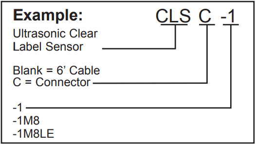
How to Specify
- Select Sensor:
Ultrasonic Clear Label Sensor - Select Cable:
Blank = 6’ (1.8m) Cable
C = Connector M12, 5-Pin
(Standard) - Select Connector:
-1 = Standard M12 Connector, see #2 Includes both NPN and PNP
-1M8 = M8, 4-Pin Connector NPN/PNP Software Selectable
-1M8LE = Wired like LER
Advanced Options
To access Advance Options, press and hold the Menu button during power up.
Press the Menu button to move from screen to screen.
Press either the ![]() or
or ![]() button to select.
button to select.
- Factory Reset
 Press either the or button to initiate factory reset.
Note: Advanced Option screen will time out in 5 minutes. - Input Mode (-1, -1M8 models only)
 Press either the or button to toggle to PNP / Source or NPN / Sink.
 - Timer Features
 Press either the or button to toggle to Enable or Disable.
 - Factory Diagnostics/Sensor Scope
 Press either the or button to toggle to Enable or Disable.
Returns to Main Screen
Remote Input Signals
Gap Set: Pulse once, 40ms to 400ms.
 Label Set: Pulse twice, 40ms to 400ms, with 40ms to 400ms idle time between pulses.
 Dynamic Set: Hold Remote Input on for more than 750ms, pull labels and gaps through sensor, release Remote Input line and sensor returns to Run mode.
 Note: Waveforms shown correspond to PNP input mode.
![]() 863 BOWSPRIT ROAD, CHULA VISTA, CA 91914, U.S.A.
863 BOWSPRIT ROAD, CHULA VISTA, CA 91914, U.S.A.
PHONES: (619) 616 7350, WWW.LOGICBUS.COM
![]() P.O. BOX 25135, TAMPA, FL 33622-5135
P.O. BOX 25135, TAMPA, FL 33622-5135
813-886-4000 / 800-237-0946
ttco.com / info@ttco.com
Documents / Resources
 |
Logicbus CLS-1 UltraSonic Clear LabelSensor [pdf] Instruction Manual CLS-1 UltraSonic Clear LabelSensor, CLS-1, UltraSonic Clear LabelSensor, Clear LabelSensor, LabelSensor |