![]() LED High Ceiling Panel
LED High Ceiling Panel
Installation Instructions
Selectable Output Series | 2′ x 2′, 2′ x 4′
WHAT COMES IN THE BOX
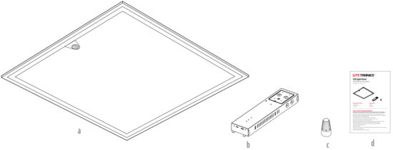
(a) LED High Ceiling Panel
(b) Driver box
(c) Wire Nut (x5)
(d) Installation Instructions
(e) Screw (x2)
TOOLS NEEDED
Wire Stripper
Wire Cutter
Phillips Screwdriver
SAFETY INSTRUCTIONS AND WARNINGS
WHEN USING ELECTICAL EQUIPMENT, BASIC SAFETY PRECAUTIONS SHOULD ALWAYS BE OBSERVED.
READ CAREFULLY BEFORE INSTALLING FIXTURE. RETAIN THESE INSTRUCTIONS FOR FUTURE REFERENCE.
Litetronics fixtures must be wired in accordance with the National Electrical Code and all applicable local codes.
Risk of fire or electric shock. High Ceiling Panel installation requires knowledge of luminaires electrical systems. If not qualified, do not attempt installation. Contact a qualified electrician.
Be certain electrical power is OFF before and during installation and maintenance.
High Ceiling Panel must be connected to a wiring system with an equipment – grounding conductor.
Make sure the supply voltage is the same as the rated luminaire voltage.
Only the open holes indicated in the photographs and/or drawings may be made or altered as a result of this kit installation. Do not leave any other open holes in an enclosure of wiring or electrical components.
To prevent wiring damage or abrasion, do not expose wiring to edges of sheet metal or sharp objects.
No user serviceable parts inside of High Ceiling Panel.
Suitable for damp locations.
Suitable for 9/16” or 15/16” Flat Tee Grid in both insulated ceilings and non-insulated ceilings. Access above ceiling required.
Vapor barrier must be suitable for 90° C.
Fixture to be independently supported to building structure.
INSTALLATION PROCEDURE
READ ALL INSTRUCTIONS BEFORE BEGINNING INSTALLATION
Unbox and inspect the High Ceiling Panel to understand it’s components.
- Turn off power at the electrical panel.
- Connect the driver to panel with quick plug connector on desk or floor.
- Push the driver into the slot position and tighten the screws.
- Before installing, locate the grid clips on your panel; bend them up and out so they can rest on top of the grid.
- Unscrew and remove the driver cover to access the input ports, ground and dimming wires.
- Locate the adjustable wattage and CCT slide switches on the side of the driver and set to the desired wattage and CCT.
See slide switch settings below.
WATTAGE SLIDE SWITCH SETTINGS
2′ x 2′WAATTAGE 80W 100W 120W 150W 170W 215W Note: Watts default setting set to 215W.
2′ x 4′WAATTAGE 105W 145W 180W 260W 290W 325W Note: Watts default setting set to 325W.
CCT SLIDE SWITCH SETTINGS5000K 4000K Note: CCT default setting set to 5000K.
- Remove the ceiling tile or existing fixture from the grid ceiling space.
- Tilt and raise the panel up into the empty grid space, then lower until the grid clips catch on the tee-grid bar.
Attach the panel to the building with support wires (not included) using the hole in the grid clip. - Remove one conduit knock-out from the driver, then run branch power wire from the conduit to the driver.
- Make wiring connections using wire nuts.
a. Connect the live power (black) line to ACL (Black)
b. Connect the neutral(white) line to ACN (White)
c Connect the green ground line to GND (Green)
d. Connect the wires from driver to panel lines via quick connect.
● Driver DIM + (Purple) to panel (Purple).
● DIM- (Pink) to panel (Pink).
● Sensor DIM + (White) to panel (Black / White)
e. If0-10V dimming is required, connect incoming dimming lines from dimmer to the Driver DIM+ (Purple) and
DIM- (Gray/Pink) wires via quick connect.
Follow dimmer manufacturers instruction
Note: If sensor (optional) is required, then use these compatible sensors SCO05, SC006, SC008 (sold separately). - Close the driver cover and secure it with the screw.
DRIVER BOX ASSEMBLING
- Connect the driver to the panel with quick plug connector.

- Push the driver into the slot position.

- Lock the driver box on the bracket by screws.


The information and product specifications contained in these instructions are based upon data believed to be accurate at the time of printing. This information is subject to change without notice and without incurring liability. If you have questions regarding specific product details, please contact us at 800-860-3392 or via email at customerservice@litetronics.com.
To check for an updated version of these instructions, please visit www.litetronics.com.
Thank you for choosing
![]() 6969 W. 73rd Street
6969 W. 73rd Street
Bedford Park, IL 60638
WWW.LITETRONICS.COM
CustomerService@Litetronics.com or 1-800-860-3392 10/21/24-V1.3
Documents / Resources
 |
LITETRONICS LED High Ceiling Panel with Sensor Socket [pdf] Installation Guide LED High Ceiling Panel with Sensor Socket, High Ceiling Panel with Sensor Socket, Ceiling Panel with Sensor Socket, Panel with Sensor Socket, Sensor Socket, Socket |